EP0960552B1 - Alimentation en micro-ondes d'une cavite de four - Google Patents
Alimentation en micro-ondes d'une cavite de four Download PDFInfo
- Publication number
- EP0960552B1 EP0960552B1 EP98910637A EP98910637A EP0960552B1 EP 0960552 B1 EP0960552 B1 EP 0960552B1 EP 98910637 A EP98910637 A EP 98910637A EP 98910637 A EP98910637 A EP 98910637A EP 0960552 B1 EP0960552 B1 EP 0960552B1
- Authority
- EP
- European Patent Office
- Prior art keywords
- slot
- dimension
- coupling
- waveguide
- elongated
- Prior art date
- Legal status (The legal status is an assumption and is not a legal conclusion. Google has not performed a legal analysis and makes no representation as to the accuracy of the status listed.)
- Expired - Lifetime
Links
- 230000008878 coupling Effects 0.000 claims abstract description 44
- 238000010168 coupling process Methods 0.000 claims abstract description 44
- 238000005859 coupling reaction Methods 0.000 claims abstract description 44
- 238000000034 method Methods 0.000 claims abstract description 7
- 230000005284 excitation Effects 0.000 claims description 4
- 230000005855 radiation Effects 0.000 claims description 3
- 230000003247 decreasing effect Effects 0.000 claims description 2
- 230000007704 transition Effects 0.000 claims description 2
- 238000009826 distribution Methods 0.000 description 4
- 238000004519 manufacturing process Methods 0.000 description 3
- 238000003466 welding Methods 0.000 description 3
- 238000010438 heat treatment Methods 0.000 description 2
- 230000001681 protective effect Effects 0.000 description 2
- 238000005452 bending Methods 0.000 description 1
- 230000015572 biosynthetic process Effects 0.000 description 1
- 238000010276 construction Methods 0.000 description 1
- 230000005684 electric field Effects 0.000 description 1
- 230000004907 flux Effects 0.000 description 1
- 230000001939 inductive effect Effects 0.000 description 1
- 238000013021 overheating Methods 0.000 description 1
- 230000001902 propagating effect Effects 0.000 description 1
- 238000007789 sealing Methods 0.000 description 1
Images
Classifications
-
- H—ELECTRICITY
- H05—ELECTRIC TECHNIQUES NOT OTHERWISE PROVIDED FOR
- H05B—ELECTRIC HEATING; ELECTRIC LIGHT SOURCES NOT OTHERWISE PROVIDED FOR; CIRCUIT ARRANGEMENTS FOR ELECTRIC LIGHT SOURCES, IN GENERAL
- H05B6/00—Heating by electric, magnetic or electromagnetic fields
- H05B6/64—Heating using microwaves
- H05B6/70—Feed lines
- H05B6/707—Feed lines using waveguides
-
- H—ELECTRICITY
- H05—ELECTRIC TECHNIQUES NOT OTHERWISE PROVIDED FOR
- H05B—ELECTRIC HEATING; ELECTRIC LIGHT SOURCES NOT OTHERWISE PROVIDED FOR; CIRCUIT ARRANGEMENTS FOR ELECTRIC LIGHT SOURCES, IN GENERAL
- H05B6/00—Heating by electric, magnetic or electromagnetic fields
- H05B6/64—Heating using microwaves
- H05B6/70—Feed lines
Definitions
- the present invention relates to microwave feeding of a cavity in a microwave oven employing an elongated coupling slot made in a cavity wall, which slot is fed from a waveguide externally connected thereto.
- the width (so-called a-dimension) of the feeding waveguide be maintained in the whole slot area, despite the fact that the width (a-dimension) of the selected coupling slot is significantly smaller than the a-dimension of the waveguide.
- This can cause problems with the required spot welding in view of the plate bending desired in connection with manufacturing, as well as with concentrations of conduction current in the cavity wall plate adjacent to the slot in the area between the respective slot ends and the side wall connection associated with the waveguide.
- the latter is particularly pronounced in connection with simple coupling slots of the so-called H-type and when TE10 mode fields are employed.
- CH-A-684 373 discloses a microwave oven having a slot in the shape of a cross.
- a main object of the present invention is to make possible microwave feeding employing a relatively small coupling slot while achieving essentially the type of field pattern which can be provided by a slot with a small a-dimension, despite the fact that the feeding waveguide employed has a considerably larger a-dimension than the coupling slot employed.
- Another object of the present invention is substantially to obviate the problems described above.
- a further object of the present invention is to make possible microwave feeding with increased flexibility with respect to the constructive design of the coupling slot in the cavity wall and the connection thereto of the feeding waveguide.
- Yet another object of the present invention is to make possible microwave feeding which provides an additional degree of constructive freedom with respect to the action on the wall current distribution in the slot area and thereby the excitation of the cavity and the heating pattern for certain loads.
- the basis of the invention is thus that it has been found possible with simple means to affect the current distribution in the cavity wall areas on each side of the microwave radiating slot part out towards the respective side walls of the feeding waveguide.
- Such action can be achieved according to the invention by the slotting of said areas from the radiating slot part, whereby such current paths as would exist in the absence of slotting are cut off, which leads to a more even current distribution without current concentrations occurring in the areas in question.
- the slotting according to the invention can be seen as the arrangement of an extension of the radiating coupling slot, that is, of its main part, and is effected in such a way that no appreciable microwave radiation into the cavity is obtained directly from the extra slot areas achieved as a result of the slotting.
- these additional slot areas will have the nature of secondary surfaces to the radiating main surface of the coupling slot.
- the slots are thus made narrow, that is, with a small height- or cross-dimension. This is possible because the flash-over risk will be minimal, since the electric field (in the slot plane) is at its lowest level in the areas in question and increases towards the radiating main part of the coupling slot, something which applies to, for example, TE10 mode fields.
- a "pocket" is created in the feeding waveguide which, depending on the geometry, will constitute an inductive or capacitive member, as well as a capacitive stretch between the cavity wall at the secondary slot surface and the opposite waveguide wall. Seen from the waveguide, the pocket will function as if it were at least substantially closed, that is, as if the extra slotting did not exist. This makes it possible to affect both the field image of the coupling slot and the wave impedance for the propagating mode of the waveguide.
- the invention provides better constructive opportunities for spot connections with a mutual spacing which eliminates microwave leakage between the waveguide and cavity plates.
- microwave fields of the TE10 type are concerned, the power flux density which can arise at the secondary slot areas is relatively speaking very small, which further obviates any leakage problems.
- a device for microwave feeding of a cavity in a microwave oven is provided, as defined in attached claim 1. It is a preferred feature that the a-dimension of the main part of the coupling slot together with the length dimension of the slot extensions essentially correspond to the a-dimension of the connected waveguide.
- the coupling slot has an essentially rectangular main part, from which a slot extension originates at each short end.
- the slot extensions can have an essentially constant cross-dimension, that is, have an essentially rectangular shape, or alternatively, in the direction away from the main part of the coupling slot, have a decreasing cross- or height-dimension.
- the slot edge of the cavity wall is rounded in the wall plane at least in an upper transition between the main part of the coupling slot and the respective slot extensions. This results in the formation of a configuration which can be compared to a "curtained" slot.
- the respective slot extensions form an extension, projecting directly outwards, of the lower edge area of the main part of the coupling slot
- the slot extensions can be arranged at a different height relative to the slot, e.g. at the top (reversed "curtain configuration") or symmetrically on the halfway point of the slot.
- an effective slot cross-dimension that is b-dimension, which typically is about 10 times greater than the cross-dimension of the slot extensions, has been found suitable.
- a method is provided as reported in the attached claim 9.
- the slot extensions are preferably dimensioned so that no appreciable microwave radiation is received directly from the slot extensions into the cavity.
- the extent given to the slot extensions is such that together with the a-dimension of the main part of the coupling slot they essentially correspond to the a-dimension of the connected waveguide.
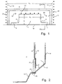
- Figs 1 and 2 illustrate an example of the arrangement of a coupling slot according to the invention in an otherwise conventional microwave oven for domestic use.
- the coupling slot 1 is arranged in a stamped (seen from inside the cavity room 2), rectangular slot wall area 3 in the lower part of a cavity wall 4.
- the coupling slot 1 comprises a rectangular main part 5, which in its lower part is provided with rectangular slot extensions 6, 7 extending to each side.
- the connection between the respective slot extensions 6 and 7 and main slot part 5 is rounded at the top, as shown at 8, 9.
- the slot extensions 6, 7 essentially extend to the side walls of the posteriorly situated feeding waveguide, which side walls are indicated by dashed lines 10, 11.
- the width of the waveguide, that is its a-dimension a v corresponds to the width of the stamped area 3.
- the effective a-dimension of the coupling slot is a s , that is, the width of the main part 5.
- the b-dimension of the main part is designated b in Fig. 1.
- the feeding wave guide has a front wall 13, which is galvanically connected to and follows the cavity wall 4, and a back wall 14, whose lowest part extends obliquely downwards forwards and under the coupling slot 1 while forming the straight lower edge 19 of the slot, to connect with the underside of the cavity bottom 15.
- a special pocket 17 is formed with a capacitive stretch C behind each slot extension 6, 7, that is, between the back wall 14 of the waveguide and the "curtain-like" part of the wall area 3 (see Fig. 1) with the posteriorly situated front waveguide wall 13 which is located above the slot extension.
- the configuration provided by said pocket will affect the microwave conditions.
- the waveguide is connected to the cavity by a number of spot welds.
- the side walls 10 and 11 of the waveguide are connected to the front wall 13 of the waveguide (and thereby indirectly to the cavity wall 4) by vertical rows of spot welds 21, 22.
- the front wall 13 of the waveguide is connected to the wall area 3 above the upper edge of the main slot part 5 by a horizontal row of spot welds 23.
- the lower end part 25 of the back wall 14 of the waveguide is connected to the overlapping cavity bottom 15 by a horizontal row of spot welds (of which one is indicated at 27) which extends along the whole wall area 3, that is, along the whole width of the waveguide.
- a protective plate e.g. a micanite plate, as is indicated at 31 in Fig. 2.
- This plate is dimensioned so that it fits sealingly into the stamped wall area 3 while connecting to the cavity bottom 15, which provides an even cavity wall and an attractive overall impression.
- the protective plate 31 is suitably attached with the aid of screws which are fixed in holes 33 in the wall area 3, whereby, simultaneously, an extra connection and galvanic contact between the cavity wall 4 and the posteriorly situated waveguide wall 13 are achieved.
Landscapes
- Physics & Mathematics (AREA)
- Electromagnetism (AREA)
- Constitution Of High-Frequency Heating (AREA)
- Tunnel Furnaces (AREA)
Abstract
Claims (12)
- Dispositif d'alimentation en microondes d'une cavité (2) d'un four à microondes, comprenant une fente allongée de couplage (1) formée dans une paroi (4) d'une cavité et un guide d'onde externe (13, 14) qui lui est raccordé, la fente allongée de couplage (1) ayant une dimension transversale de fente (b) perpendiculairement à la direction d'allongement de la fente, caractérisé en ce que la fente de couplage (1) comporte une partie principale allongée de fente (5) ayant à ses extrémités de fente un prolongement de fente (6, 7) de section nettement plus petite que la section (b) de la partie principale allongée de fente (5) de la fente de couplage (1).
- Dispositif selon la revendication 1, caractérisé en ce que la partie principale allongée de fente (5) de la fente de couplage (1) est essentiellement rectangulaire et le prolongement de chaque fente (6, 7) provient de cette partie.
- Dispositif selon la revendication 1 ou 2, caractérisé en ce que chaque prolongement de fente (6, 7) a une forme pratiquement rectangulaire.
- Dispositif selon la revendication 1 ou 2,
caractérisé en ce que chaque prolongement de fente (6, 7) a une section qui diminue en direction opposée à la partie principale allongée de fente (5) de la fente de couplage (1). - Dispositif selon l'une quelconque des revendications précédentes, caractérisé en ce que la paroi de la cavité (4) délimite un plan de paroi ayant un bord de fente entre le plan de paroi et la fente de couplage (1), et le bord de fente de la paroi de la cavité (4) est arrondi dans le plan de la paroi au moins à une transition supérieure (8, 9) entre la partie principale allongée de fente (5) de la fente de couplage (1) et le prolongement respectif de fente (6, 7).
- Dispositif selon l'une quelconque des revendications précédentes, caractérisé en ce que la largeur (as) de la partie principale allongée de fente (5) de la fente de couplage (1) ainsi que la dimension de longueur des prolongements de fente (6, 7) correspondent à la largeur (av) du guide d'onde raccordé (13, 14).
- Dispositif selon l'uns quelconque des revendications précédentes, caractérisé en ce que la fente de couplage (1) a une région de bord inférieur, et chaque prolongement de fente (6, 7) constitue un prolongement dépassant directement vers l'extérieur de la région de bord inférieur de la partie principale allongée de fente (5) de la fente de couplage (1).
- Dispositif selon l'une quelconque des revendications précédentes, caractérisé en ce que la partie principale allongée de fente (5) de la fente de couplage (1) a une dimension transversale (b) qui est habituellement supérieure d'un facteur 10 à la dimension transversale des prolongements de fente (6, 7).
- Procédé d'alimentation en microondes d'une cavité (2) d'un four à microondes par une fente allongée de couplage (1) qui est alimentée par un guide d'ondes extérieur (13, 14), dans lequel une partie principale allongée de fente (5) dont la largeur efficace (as) est nettement inférieure à la largeur (av) du guide d'onde est utilisée, caractérisé par l'adaptation de la fente allongée de couplage (1) au guide d'onde et à une excitation voulue de la cavité par connexion d'un prolongement de fente (6, 7) dont la dimension transversale est nettement inférieure à la dimension transversale (b) de la partie principale allongée de fente de la fente de couplage (1) aux extrémités respectives de la partie principale allongée de fente (5) de la fente de couplage (1), la dimension transversale étant perpendiculaire à la direction d'allongement.
- Procédé selon la revendication 9, caractérisé en ce que chaque prolongement de fente (6, 7) a une longueur telle que, avec la largeur (as) de la partie principale allongée de fente (5) de la fente de couplage (1), il corresponde essentiellement à la largeur (av) du guide d'onde raccordé.
- Procédé selon la revendication 9 ou 10, caractérisé par un nouvel ajustement, après la connexion des prolongements de fente (6, 7), des dimensions, et en particulier de la largeur (as), de la partie principale allongée de fente (5) de la fente de couplage (1).
- Procédé selon la revendication 9, 10 ou 11, caractérisé par un dimensionnement des prolongements de fente (6, 7) de manière qu'aucun rayonnement notable de microondes ne soit directement reçu depuis les prolongements de fente (6, 7) par la cavité (2).
Applications Claiming Priority (3)
| Application Number | Priority Date | Filing Date | Title |
|---|---|---|---|
| SE9700530 | 1997-02-13 | ||
| SE9700530A SE513617C2 (sv) | 1997-02-13 | 1997-02-13 | Mikrovågsmatning av ugnskavitet |
| PCT/EP1998/000711 WO1998036619A1 (fr) | 1997-02-13 | 1998-02-09 | Alimentation en micro-ondes d'une cavite de four |
Publications (2)
| Publication Number | Publication Date |
|---|---|
| EP0960552A1 EP0960552A1 (fr) | 1999-12-01 |
| EP0960552B1 true EP0960552B1 (fr) | 2003-05-02 |
Family
ID=20405802
Family Applications (1)
| Application Number | Title | Priority Date | Filing Date |
|---|---|---|---|
| EP98910637A Expired - Lifetime EP0960552B1 (fr) | 1997-02-13 | 1998-02-09 | Alimentation en micro-ondes d'une cavite de four |
Country Status (13)
| Country | Link |
|---|---|
| US (1) | US6333496B1 (fr) |
| EP (1) | EP0960552B1 (fr) |
| JP (1) | JP2001511938A (fr) |
| KR (1) | KR20000071041A (fr) |
| CN (1) | CN1247686A (fr) |
| AU (1) | AU719744B2 (fr) |
| BR (1) | BR9807341A (fr) |
| DE (1) | DE69814043T2 (fr) |
| ES (1) | ES2199432T3 (fr) |
| SE (1) | SE513617C2 (fr) |
| SK (1) | SK91499A3 (fr) |
| TR (1) | TR199901948T2 (fr) |
| WO (1) | WO1998036619A1 (fr) |
Families Citing this family (7)
| Publication number | Priority date | Publication date | Assignee | Title |
|---|---|---|---|---|
| EP1534999B1 (fr) | 2002-07-05 | 2017-11-01 | TurboChef Technologies, Inc. | Four de cuisson rapide |
| US9351495B2 (en) | 2002-07-05 | 2016-05-31 | Turbochef Technologies, Inc. | Air fryer |
| US8011293B2 (en) | 2003-07-07 | 2011-09-06 | Turbochef Technologies, Inc. | Speed cooking oven with sloped oven floor and reversing gas flow |
| WO2005041672A2 (fr) * | 2003-10-21 | 2005-05-12 | Global Appliance Technologies, Inc. | Four de cuisson rapide a antenne hyperfrequences fendue |
| WO2007038196A2 (fr) * | 2005-09-22 | 2007-04-05 | Eastman Chemical Company | Reacteur a micro-ondes comprenant un guide d'onde a reseau de fentes couple a un coude de guide d'onde |
| CN101583837B (zh) * | 2005-09-22 | 2012-02-15 | 伊斯曼化学公司 | 具有开缝阵列波导的微波反应器 |
| US20120160839A1 (en) | 2010-12-23 | 2012-06-28 | Eastman Chemical Company | Microwave wood heater with enhanced spatial usage efficiency and uniformity of heat distribution |
Family Cites Families (9)
| Publication number | Priority date | Publication date | Assignee | Title |
|---|---|---|---|---|
| US3764770A (en) * | 1972-05-03 | 1973-10-09 | Sage Laboratories | Microwave oven |
| US4159406A (en) * | 1977-05-31 | 1979-06-26 | Whirlpool Corporation | Waveguide assembly for microwave oven |
| JPS5989929A (ja) * | 1982-11-12 | 1984-05-24 | Matsushita Electric Ind Co Ltd | 高周波加熱装置 |
| JP2614336B2 (ja) * | 1989-11-24 | 1997-05-28 | 株式会社東芝 | 高周波加熱調理装置 |
| FR2673350B1 (fr) * | 1991-02-22 | 2001-09-28 | Moulinex Sa | Guide d'ondes pour four a micro-ondes. |
| CH684373A5 (de) * | 1992-10-29 | 1994-08-31 | Inwave Ag | Vorrichtung zur Einkopplung von Mikrowellen. |
| KR100186479B1 (ko) * | 1996-07-11 | 1999-03-20 | 구자홍 | 전자레인지의 도파관 구조 |
| KR19980017873A (ko) * | 1996-08-31 | 1998-06-05 | 배순훈 | 전자렌지의 도파관 구조 |
| KR100207276B1 (ko) * | 1997-03-10 | 1999-07-15 | 전주범 | 전자렌지의 초고주파유도구조 |
-
1997
- 1997-02-13 SE SE9700530A patent/SE513617C2/sv not_active IP Right Cessation
-
1998
- 1998-02-09 BR BR9807341-9A patent/BR9807341A/pt not_active IP Right Cessation
- 1998-02-09 WO PCT/EP1998/000711 patent/WO1998036619A1/fr not_active Ceased
- 1998-02-09 AU AU64955/98A patent/AU719744B2/en not_active Ceased
- 1998-02-09 TR TR1999/01948T patent/TR199901948T2/xx unknown
- 1998-02-09 KR KR1019997007308A patent/KR20000071041A/ko not_active Ceased
- 1998-02-09 CN CN98802486A patent/CN1247686A/zh active Pending
- 1998-02-09 US US09/367,375 patent/US6333496B1/en not_active Expired - Fee Related
- 1998-02-09 SK SK914-99A patent/SK91499A3/sk unknown
- 1998-02-09 JP JP53531998A patent/JP2001511938A/ja active Pending
- 1998-02-09 ES ES98910637T patent/ES2199432T3/es not_active Expired - Lifetime
- 1998-02-09 DE DE69814043T patent/DE69814043T2/de not_active Expired - Fee Related
- 1998-02-09 EP EP98910637A patent/EP0960552B1/fr not_active Expired - Lifetime
Also Published As
| Publication number | Publication date |
|---|---|
| CN1247686A (zh) | 2000-03-15 |
| KR20000071041A (ko) | 2000-11-25 |
| WO1998036619A1 (fr) | 1998-08-20 |
| US6333496B1 (en) | 2001-12-25 |
| ES2199432T3 (es) | 2004-02-16 |
| JP2001511938A (ja) | 2001-08-14 |
| SE9700530D0 (sv) | 1997-02-13 |
| SK91499A3 (en) | 2000-08-14 |
| DE69814043T2 (de) | 2004-03-04 |
| BR9807341A (pt) | 2000-04-25 |
| SE513617C2 (sv) | 2000-10-09 |
| SE9700530L (sv) | 1998-08-14 |
| AU719744B2 (en) | 2000-05-18 |
| AU6495598A (en) | 1998-09-08 |
| EP0960552A1 (fr) | 1999-12-01 |
| TR199901948T2 (xx) | 2000-03-21 |
| DE69814043D1 (de) | 2003-06-05 |
Similar Documents
| Publication | Publication Date | Title |
|---|---|---|
| JP3710182B2 (ja) | 電波遮蔽構造を有する電子レンジのドア | |
| JP2739922B2 (ja) | シールド付き電気コネクタ | |
| US8222977B2 (en) | Metal plate for preventing radiowave leakage through an aperture in a waveguide body | |
| EP0960552B1 (fr) | Alimentation en micro-ondes d'une cavite de four | |
| SK286693B6 (sk) | Usporiadanie dvojíc kontaktov pre zásuvku elektrického zásuvného spoja | |
| US5654722A (en) | Device at antenna systems for generating radio waves | |
| CN109149276A (zh) | 电连接器 | |
| US11764524B2 (en) | Terminal connector | |
| KR200150292Y1 (ko) | 전자레인지의 도파관 구조 | |
| KR100300116B1 (ko) | 전자렌지 | |
| HK1026564A (en) | Microwave feeding of an oven cavity | |
| KR102898725B1 (ko) | 다중 쵸크를 구비하는 오븐 | |
| KR200224559Y1 (ko) | 전자레인지의 고압캐패시터 장착구조 | |
| JP2002344210A (ja) | 非放射性誘電体線路と導波管の変換回路 | |
| KR100310366B1 (ko) | 전자렌지용 마그네트론 | |
| KR200227950Y1 (ko) | 안정기 케이스 | |
| KR950000256Y1 (ko) | 전자레인지의 전자파 송출 장치 | |
| CN120834426A (zh) | 腔体天线及电子设备 | |
| US6254433B1 (en) | Multiple pole connector with shield plate | |
| KR20030079594A (ko) | 전자레인지의 도파관 장착구조 | |
| KR0160844B1 (ko) | 마그네트론의 자극구조 | |
| KR100300115B1 (ko) | 전자렌지 | |
| KR200373470Y1 (ko) | 전자레인지 | |
| KR0116571Y1 (ko) | 전자레인지의 반사파 흡수장치 | |
| JPS6230798Y2 (fr) |
Legal Events
| Date | Code | Title | Description |
|---|---|---|---|
| PUAI | Public reference made under article 153(3) epc to a published international application that has entered the european phase |
Free format text: ORIGINAL CODE: 0009012 |
|
| 17P | Request for examination filed |
Effective date: 19990617 |
|
| AK | Designated contracting states |
Kind code of ref document: A1 Designated state(s): DE ES FR GB IT SE |
|
| 17Q | First examination report despatched |
Effective date: 20010405 |
|
| GRAH | Despatch of communication of intention to grant a patent |
Free format text: ORIGINAL CODE: EPIDOS IGRA |
|
| GRAH | Despatch of communication of intention to grant a patent |
Free format text: ORIGINAL CODE: EPIDOS IGRA |
|
| GRAA | (expected) grant |
Free format text: ORIGINAL CODE: 0009210 |
|
| AK | Designated contracting states |
Designated state(s): DE ES FR GB IT SE |
|
| REG | Reference to a national code |
Ref country code: GB Ref legal event code: FG4D |
|
| REF | Corresponds to: |
Ref document number: 69814043 Country of ref document: DE Date of ref document: 20030605 Kind code of ref document: P |
|
| REG | Reference to a national code |
Ref country code: SE Ref legal event code: TRGR |
|
| PG25 | Lapsed in a contracting state [announced via postgrant information from national office to epo] |
Ref country code: GB Free format text: LAPSE BECAUSE OF NON-PAYMENT OF DUE FEES Effective date: 20040209 |
|
| PG25 | Lapsed in a contracting state [announced via postgrant information from national office to epo] |
Ref country code: SE Free format text: LAPSE BECAUSE OF NON-PAYMENT OF DUE FEES Effective date: 20040210 Ref country code: ES Free format text: LAPSE BECAUSE OF NON-PAYMENT OF DUE FEES Effective date: 20040210 |
|
| REG | Reference to a national code |
Ref country code: ES Ref legal event code: FG2A Ref document number: 2199432 Country of ref document: ES Kind code of ref document: T3 |
|
| ET | Fr: translation filed | ||
| PLBE | No opposition filed within time limit |
Free format text: ORIGINAL CODE: 0009261 |
|
| STAA | Information on the status of an ep patent application or granted ep patent |
Free format text: STATUS: NO OPPOSITION FILED WITHIN TIME LIMIT |
|
| 26N | No opposition filed |
Effective date: 20040203 |
|
| PG25 | Lapsed in a contracting state [announced via postgrant information from national office to epo] |
Ref country code: DE Free format text: LAPSE BECAUSE OF NON-PAYMENT OF DUE FEES Effective date: 20040901 |
|
| EUG | Se: european patent has lapsed | ||
| GBPC | Gb: european patent ceased through non-payment of renewal fee |
Effective date: 20040209 |
|
| PG25 | Lapsed in a contracting state [announced via postgrant information from national office to epo] |
Ref country code: FR Free format text: LAPSE BECAUSE OF NON-PAYMENT OF DUE FEES Effective date: 20041029 |
|
| REG | Reference to a national code |
Ref country code: FR Ref legal event code: ST |
|
| PG25 | Lapsed in a contracting state [announced via postgrant information from national office to epo] |
Ref country code: IT Free format text: LAPSE BECAUSE OF NON-PAYMENT OF DUE FEES;WARNING: LAPSES OF ITALIAN PATENTS WITH EFFECTIVE DATE BEFORE 2007 MAY HAVE OCCURRED AT ANY TIME BEFORE 2007. THE CORRECT EFFECTIVE DATE MAY BE DIFFERENT FROM THE ONE RECORDED. Effective date: 20050209 |
|
| REG | Reference to a national code |
Ref country code: ES Ref legal event code: FD2A Effective date: 20040210 |