EP0960552B1 - Microwave feeding of an oven cavity - Google Patents
Microwave feeding of an oven cavity Download PDFInfo
- Publication number
- EP0960552B1 EP0960552B1 EP98910637A EP98910637A EP0960552B1 EP 0960552 B1 EP0960552 B1 EP 0960552B1 EP 98910637 A EP98910637 A EP 98910637A EP 98910637 A EP98910637 A EP 98910637A EP 0960552 B1 EP0960552 B1 EP 0960552B1
- Authority
- EP
- European Patent Office
- Prior art keywords
- slot
- dimension
- coupling
- waveguide
- elongated
- Prior art date
- Legal status (The legal status is an assumption and is not a legal conclusion. Google has not performed a legal analysis and makes no representation as to the accuracy of the status listed.)
- Expired - Lifetime
Links
- 230000008878 coupling Effects 0.000 claims abstract description 44
- 238000010168 coupling process Methods 0.000 claims abstract description 44
- 238000005859 coupling reaction Methods 0.000 claims abstract description 44
- 238000000034 method Methods 0.000 claims abstract description 7
- 230000005284 excitation Effects 0.000 claims description 4
- 230000005855 radiation Effects 0.000 claims description 3
- 230000003247 decreasing effect Effects 0.000 claims description 2
- 230000007704 transition Effects 0.000 claims description 2
- 238000009826 distribution Methods 0.000 description 4
- 238000004519 manufacturing process Methods 0.000 description 3
- 238000003466 welding Methods 0.000 description 3
- 238000010438 heat treatment Methods 0.000 description 2
- 230000001681 protective effect Effects 0.000 description 2
- 238000005452 bending Methods 0.000 description 1
- 230000015572 biosynthetic process Effects 0.000 description 1
- 238000010276 construction Methods 0.000 description 1
- 230000005684 electric field Effects 0.000 description 1
- 230000004907 flux Effects 0.000 description 1
- 230000001939 inductive effect Effects 0.000 description 1
- 238000013021 overheating Methods 0.000 description 1
- 230000001902 propagating effect Effects 0.000 description 1
- 238000007789 sealing Methods 0.000 description 1
Images
Classifications
-
- H—ELECTRICITY
- H05—ELECTRIC TECHNIQUES NOT OTHERWISE PROVIDED FOR
- H05B—ELECTRIC HEATING; ELECTRIC LIGHT SOURCES NOT OTHERWISE PROVIDED FOR; CIRCUIT ARRANGEMENTS FOR ELECTRIC LIGHT SOURCES, IN GENERAL
- H05B6/00—Heating by electric, magnetic or electromagnetic fields
- H05B6/64—Heating using microwaves
- H05B6/70—Feed lines
- H05B6/707—Feed lines using waveguides
-
- H—ELECTRICITY
- H05—ELECTRIC TECHNIQUES NOT OTHERWISE PROVIDED FOR
- H05B—ELECTRIC HEATING; ELECTRIC LIGHT SOURCES NOT OTHERWISE PROVIDED FOR; CIRCUIT ARRANGEMENTS FOR ELECTRIC LIGHT SOURCES, IN GENERAL
- H05B6/00—Heating by electric, magnetic or electromagnetic fields
- H05B6/64—Heating using microwaves
- H05B6/70—Feed lines
Definitions
- the present invention relates to microwave feeding of a cavity in a microwave oven employing an elongated coupling slot made in a cavity wall, which slot is fed from a waveguide externally connected thereto.
- the width (so-called a-dimension) of the feeding waveguide be maintained in the whole slot area, despite the fact that the width (a-dimension) of the selected coupling slot is significantly smaller than the a-dimension of the waveguide.
- This can cause problems with the required spot welding in view of the plate bending desired in connection with manufacturing, as well as with concentrations of conduction current in the cavity wall plate adjacent to the slot in the area between the respective slot ends and the side wall connection associated with the waveguide.
- the latter is particularly pronounced in connection with simple coupling slots of the so-called H-type and when TE10 mode fields are employed.
- CH-A-684 373 discloses a microwave oven having a slot in the shape of a cross.
- a main object of the present invention is to make possible microwave feeding employing a relatively small coupling slot while achieving essentially the type of field pattern which can be provided by a slot with a small a-dimension, despite the fact that the feeding waveguide employed has a considerably larger a-dimension than the coupling slot employed.
- Another object of the present invention is substantially to obviate the problems described above.
- a further object of the present invention is to make possible microwave feeding with increased flexibility with respect to the constructive design of the coupling slot in the cavity wall and the connection thereto of the feeding waveguide.
- Yet another object of the present invention is to make possible microwave feeding which provides an additional degree of constructive freedom with respect to the action on the wall current distribution in the slot area and thereby the excitation of the cavity and the heating pattern for certain loads.
- the basis of the invention is thus that it has been found possible with simple means to affect the current distribution in the cavity wall areas on each side of the microwave radiating slot part out towards the respective side walls of the feeding waveguide.
- Such action can be achieved according to the invention by the slotting of said areas from the radiating slot part, whereby such current paths as would exist in the absence of slotting are cut off, which leads to a more even current distribution without current concentrations occurring in the areas in question.
- the slotting according to the invention can be seen as the arrangement of an extension of the radiating coupling slot, that is, of its main part, and is effected in such a way that no appreciable microwave radiation into the cavity is obtained directly from the extra slot areas achieved as a result of the slotting.
- these additional slot areas will have the nature of secondary surfaces to the radiating main surface of the coupling slot.
- the slots are thus made narrow, that is, with a small height- or cross-dimension. This is possible because the flash-over risk will be minimal, since the electric field (in the slot plane) is at its lowest level in the areas in question and increases towards the radiating main part of the coupling slot, something which applies to, for example, TE10 mode fields.
- a "pocket" is created in the feeding waveguide which, depending on the geometry, will constitute an inductive or capacitive member, as well as a capacitive stretch between the cavity wall at the secondary slot surface and the opposite waveguide wall. Seen from the waveguide, the pocket will function as if it were at least substantially closed, that is, as if the extra slotting did not exist. This makes it possible to affect both the field image of the coupling slot and the wave impedance for the propagating mode of the waveguide.
- the invention provides better constructive opportunities for spot connections with a mutual spacing which eliminates microwave leakage between the waveguide and cavity plates.
- microwave fields of the TE10 type are concerned, the power flux density which can arise at the secondary slot areas is relatively speaking very small, which further obviates any leakage problems.
- a device for microwave feeding of a cavity in a microwave oven is provided, as defined in attached claim 1. It is a preferred feature that the a-dimension of the main part of the coupling slot together with the length dimension of the slot extensions essentially correspond to the a-dimension of the connected waveguide.
- the coupling slot has an essentially rectangular main part, from which a slot extension originates at each short end.
- the slot extensions can have an essentially constant cross-dimension, that is, have an essentially rectangular shape, or alternatively, in the direction away from the main part of the coupling slot, have a decreasing cross- or height-dimension.
- the slot edge of the cavity wall is rounded in the wall plane at least in an upper transition between the main part of the coupling slot and the respective slot extensions. This results in the formation of a configuration which can be compared to a "curtained" slot.
- the respective slot extensions form an extension, projecting directly outwards, of the lower edge area of the main part of the coupling slot
- the slot extensions can be arranged at a different height relative to the slot, e.g. at the top (reversed "curtain configuration") or symmetrically on the halfway point of the slot.
- an effective slot cross-dimension that is b-dimension, which typically is about 10 times greater than the cross-dimension of the slot extensions, has been found suitable.
- a method is provided as reported in the attached claim 9.
- the slot extensions are preferably dimensioned so that no appreciable microwave radiation is received directly from the slot extensions into the cavity.
- the extent given to the slot extensions is such that together with the a-dimension of the main part of the coupling slot they essentially correspond to the a-dimension of the connected waveguide.
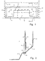
- Figs 1 and 2 illustrate an example of the arrangement of a coupling slot according to the invention in an otherwise conventional microwave oven for domestic use.
- the coupling slot 1 is arranged in a stamped (seen from inside the cavity room 2), rectangular slot wall area 3 in the lower part of a cavity wall 4.
- the coupling slot 1 comprises a rectangular main part 5, which in its lower part is provided with rectangular slot extensions 6, 7 extending to each side.
- the connection between the respective slot extensions 6 and 7 and main slot part 5 is rounded at the top, as shown at 8, 9.
- the slot extensions 6, 7 essentially extend to the side walls of the posteriorly situated feeding waveguide, which side walls are indicated by dashed lines 10, 11.
- the width of the waveguide, that is its a-dimension a v corresponds to the width of the stamped area 3.
- the effective a-dimension of the coupling slot is a s , that is, the width of the main part 5.
- the b-dimension of the main part is designated b in Fig. 1.
- the feeding wave guide has a front wall 13, which is galvanically connected to and follows the cavity wall 4, and a back wall 14, whose lowest part extends obliquely downwards forwards and under the coupling slot 1 while forming the straight lower edge 19 of the slot, to connect with the underside of the cavity bottom 15.
- a special pocket 17 is formed with a capacitive stretch C behind each slot extension 6, 7, that is, between the back wall 14 of the waveguide and the "curtain-like" part of the wall area 3 (see Fig. 1) with the posteriorly situated front waveguide wall 13 which is located above the slot extension.
- the configuration provided by said pocket will affect the microwave conditions.
- the waveguide is connected to the cavity by a number of spot welds.
- the side walls 10 and 11 of the waveguide are connected to the front wall 13 of the waveguide (and thereby indirectly to the cavity wall 4) by vertical rows of spot welds 21, 22.
- the front wall 13 of the waveguide is connected to the wall area 3 above the upper edge of the main slot part 5 by a horizontal row of spot welds 23.
- the lower end part 25 of the back wall 14 of the waveguide is connected to the overlapping cavity bottom 15 by a horizontal row of spot welds (of which one is indicated at 27) which extends along the whole wall area 3, that is, along the whole width of the waveguide.
- a protective plate e.g. a micanite plate, as is indicated at 31 in Fig. 2.
- This plate is dimensioned so that it fits sealingly into the stamped wall area 3 while connecting to the cavity bottom 15, which provides an even cavity wall and an attractive overall impression.
- the protective plate 31 is suitably attached with the aid of screws which are fixed in holes 33 in the wall area 3, whereby, simultaneously, an extra connection and galvanic contact between the cavity wall 4 and the posteriorly situated waveguide wall 13 are achieved.
Landscapes
- Physics & Mathematics (AREA)
- Electromagnetism (AREA)
- Constitution Of High-Frequency Heating (AREA)
- Tunnel Furnaces (AREA)
Abstract
Description
- The present invention relates to microwave feeding of a cavity in a microwave oven employing an elongated coupling slot made in a cavity wall, which slot is fed from a waveguide externally connected thereto.
- The dimensioning of coupling slots for microwave feeding of the kind mentioned above often causes a number of problems. The achievement of good fixing, that is, good galvanic contact, between the feeding waveguide and the cavity wall can be problematic because of inaccessibility for spot welding means which at the time of manufacture have to be inserted into and behind the slot opening in connection with the spot welding of the waveguide to the cavity. As will be appreciated, this leads to constructive limitations.
- For technical microwave reasons it is often desirable that the width (so-called a-dimension) of the feeding waveguide be maintained in the whole slot area, despite the fact that the width (a-dimension) of the selected coupling slot is significantly smaller than the a-dimension of the waveguide. This can cause problems with the required spot welding in view of the plate bending desired in connection with manufacturing, as well as with concentrations of conduction current in the cavity wall plate adjacent to the slot in the area between the respective slot ends and the side wall connection associated with the waveguide. The latter is particularly pronounced in connection with simple coupling slots of the so-called H-type and when TE10 mode fields are employed.
- CH-A-684 373 discloses a microwave oven having a slot in the shape of a cross.
- A main object of the present invention is to make possible microwave feeding employing a relatively small coupling slot while achieving essentially the type of field pattern which can be provided by a slot with a small a-dimension, despite the fact that the feeding waveguide employed has a considerably larger a-dimension than the coupling slot employed.
- Another object of the present invention is substantially to obviate the problems described above.
- A further object of the present invention is to make possible microwave feeding with increased flexibility with respect to the constructive design of the coupling slot in the cavity wall and the connection thereto of the feeding waveguide.
- Yet another object of the present invention is to make possible microwave feeding which provides an additional degree of constructive freedom with respect to the action on the wall current distribution in the slot area and thereby the excitation of the cavity and the heating pattern for certain loads.
- The above-mentioned objects are achieved by a device and a method which exhibit the features stated in the appended claims.
- The basis of the invention is thus that it has been found possible with simple means to affect the current distribution in the cavity wall areas on each side of the microwave radiating slot part out towards the respective side walls of the feeding waveguide. Such action can be achieved according to the invention by the slotting of said areas from the radiating slot part, whereby such current paths as would exist in the absence of slotting are cut off, which leads to a more even current distribution without current concentrations occurring in the areas in question.
- It has been found that such a changed current distribution does not affect the excitation of the cavity fields unfavourably, but that the risk of overheating and major current losses in the areas in question is significantly reduced. In addition, said action can be utilised to favourably adjust the excitation and the heating pattern of the cavity, as well as the impedance matching, with a basic configuration as the starting-point. In other words, an extra degree of freedom can be obtained.
- The slotting according to the invention can be seen as the arrangement of an extension of the radiating coupling slot, that is, of its main part, and is effected in such a way that no appreciable microwave radiation into the cavity is obtained directly from the extra slot areas achieved as a result of the slotting. In other words, these additional slot areas will have the nature of secondary surfaces to the radiating main surface of the coupling slot. The slots are thus made narrow, that is, with a small height- or cross-dimension. This is possible because the flash-over risk will be minimal, since the electric field (in the slot plane) is at its lowest level in the areas in question and increases towards the radiating main part of the coupling slot, something which applies to, for example, TE10 mode fields.
- Behind each secondary slot surface a "pocket" is created in the feeding waveguide which, depending on the geometry, will constitute an inductive or capacitive member, as well as a capacitive stretch between the cavity wall at the secondary slot surface and the opposite waveguide wall. Seen from the waveguide, the pocket will function as if it were at least substantially closed, that is, as if the extra slotting did not exist. This makes it possible to affect both the field image of the coupling slot and the wave impedance for the propagating mode of the waveguide.
- With respect to the required galvanic contact between the cavity and the waveguide it has been found that the invention provides better constructive opportunities for spot connections with a mutual spacing which eliminates microwave leakage between the waveguide and cavity plates. In this connection, it is also important to note that when microwave fields of the TE10 type are concerned, the power flux density which can arise at the secondary slot areas is relatively speaking very small, which further obviates any leakage problems.
- According to a first aspect of the invention, a device for microwave feeding of a cavity in a microwave oven is provided, as defined in attached claim 1. It is a preferred feature that the a-dimension of the main part of the coupling slot together with the length dimension of the slot extensions essentially correspond to the a-dimension of the connected waveguide.
- Advantageously, the coupling slot has an essentially rectangular main part, from which a slot extension originates at each short end. The slot extensions can have an essentially constant cross-dimension, that is, have an essentially rectangular shape, or alternatively, in the direction away from the main part of the coupling slot, have a decreasing cross- or height-dimension.
- Preferably, the slot edge of the cavity wall is rounded in the wall plane at least in an upper transition between the main part of the coupling slot and the respective slot extensions. This results in the formation of a configuration which can be compared to a "curtained" slot.
- Although it has been found suitable that the respective slot extensions form an extension, projecting directly outwards, of the lower edge area of the main part of the coupling slot, the skilled person will appreciate that the slot extensions can be arranged at a different height relative to the slot, e.g. at the top (reversed "curtain configuration") or symmetrically on the halfway point of the slot.
- For a 2450 MHz microwave oven for domestic use, an effective slot cross-dimension, that is b-dimension, which typically is about 10 times greater than the cross-dimension of the slot extensions, has been found suitable.
- According to a second aspect of the invention, a method is provided as reported in the attached claim 9. The slot extensions are preferably dimensioned so that no appreciable microwave radiation is received directly from the slot extensions into the cavity.
- It is a preferred feature that the extent given to the slot extensions is such that together with the a-dimension of the main part of the coupling slot they essentially correspond to the a-dimension of the connected waveguide.
- It will be appreciated that subsequent to the arrangement of the slot extensions on the basis of a basic configuration with a certain given slot main part, it is possible to further adapt the microwave feeding to the existing conditions by readjusting the dimensions of the main part, in particular its a-dimension and/or b-dimension.
- The invention will be described in more detail below by way of an embodiment with reference to the accompanying drawing.
-
- Fig. 1 is a schematic vertical partial view of a coupling slot in a cavity side wall in a microwave oven, the view being taken from inside the cavity.
- Fig. 2 is schematic vertical partial sectional view taken along line II-II in Fig. 1.
-
- Figs 1 and 2 illustrate an example of the arrangement of a coupling slot according to the invention in an otherwise conventional microwave oven for domestic use. The coupling slot 1 is arranged in a stamped (seen from inside the cavity room 2), rectangular
slot wall area 3 in the lower part of acavity wall 4. The coupling slot 1 comprises a rectangularmain part 5, which in its lower part is provided withrectangular slot extensions respective slot extensions main slot part 5 is rounded at the top, as shown at 8, 9. Theslot extensions dashed lines stamped area 3. The effective a-dimension of the coupling slot is as, that is, the width of themain part 5. The b-dimension of the main part is designated b in Fig. 1. - In addition to the indicated
side walls front wall 13, which is galvanically connected to and follows thecavity wall 4, and aback wall 14, whose lowest part extends obliquely downwards forwards and under the coupling slot 1 while forming the straightlower edge 19 of the slot, to connect with the underside of thecavity bottom 15. - As seen in Fig. 2, a
special pocket 17 is formed with a capacitive stretch C behind eachslot extension back wall 14 of the waveguide and the "curtain-like" part of the wall area 3 (see Fig. 1) with the posteriorly situatedfront waveguide wall 13 which is located above the slot extension. As mentioned above, the configuration provided by said pocket will affect the microwave conditions. - The waveguide is connected to the cavity by a number of spot welds. The
side walls front wall 13 of the waveguide (and thereby indirectly to the cavity wall 4) by vertical rows ofspot welds 21, 22. At the bottom, thefront wall 13 of the waveguide is connected to thewall area 3 above the upper edge of themain slot part 5 by a horizontal row ofspot welds 23. Finally, thelower end part 25 of theback wall 14 of the waveguide is connected to the overlappingcavity bottom 15 by a horizontal row of spot welds (of which one is indicated at 27) which extends along thewhole wall area 3, that is, along the whole width of the waveguide. - All of the spot welds mentioned above are easy to achieve from a manufacturing point of view and have been found to provide fully adequate galvanic contact and sealing against microwave leakage. In this connection, it is of particular interest that the lack of spot welds in the "curtain parts" of the
wall area 3 have not been found to cause any problems. This is particularly pronounced when non-spot-welded stretches are less than ¼ free microwave length. - It is suitable to cover the coupling slot in the usual manner with a protective plate, e.g. a micanite plate, as is indicated at 31 in Fig. 2. This plate is dimensioned so that it fits sealingly into the stamped
wall area 3 while connecting to the cavity bottom 15, which provides an even cavity wall and an attractive overall impression. Theprotective plate 31 is suitably attached with the aid of screws which are fixed inholes 33 in thewall area 3, whereby, simultaneously, an extra connection and galvanic contact between thecavity wall 4 and the posteriorly situatedwaveguide wall 13 are achieved. - The following dimensions are provided as an example of the dimensioning of a construction according to Figs 1 and 2 of a microwave oven intended for domestic use:
- A-dimension of the waveguide about 105 mm,
- A-dimension of the coupling slot about 80 mm,
- Length of slot extension about 13 mm,
- Height of slot extension about 2 mm.
Claims (12)
- A device for feeding microwaves of into a cavity (2) of a microwave oven, comprising an elongated coupling slot (1) made in a cavity wall (4) and an external waveguide (13, 14) connected thereto, the elongated coupling slot (1) having a slot cross-dimension (b) normal to the direction of elongation of the slot, characterised in that the coupling slot (1) comprises an elongated main slot part (5), having at its respective slot ends a slot extension (6, 7) with a substantially smaller cross-dimension than the cross-dimension (b) of the elongated main slot part (5) of the coupling slot (1).
- A device according to claim 1, characterised in that the elongated main slot part (5) of the coupling slot (1) is essentially rectangular, from which each slot extension (6,7) originates.
- A device according to claim 1 or 2, characterised in that each slot extension (6,7) has an essentially rectangular shape.
- A device according to claim 1 or 2, characterised in that each slot extension (6,7) has a decreasing cross-dimension in the direction away from the elongated main slot part (5) of the coupling slot (1).
- A device according to any one of the preceding claims, characterised in that the cavity wall (4) defines a wall plane having a slot edge between the wall plane and the coupling slot (1), the slot edge of the cavity wall (4) is rounded in the wall plane at least in an upper transition (8,9) between the elongated main slot part (5) of the coupling slot (1) and the respective slot extension (6,7).
- A device according to any one of the preceding claims, characterised in that the width (as) of the elongated main slot part (5) of the coupling slot (1) together with the length dimension of the slot extensions (6,7) correspond to the width (av) of the connected waveguide (13,14).
- A device according to any one of the preceding claims, characterised in that the coupling slot (1) has a lower edge area, each slot extension (6,7) constitutes an extension, projecting directly outwards, of the lower edge area of the elongated main slot part (5) of the coupling slot (1).
- A device according to any one of the preceding claims, characterised in that the elongated main slot part (5) of the coupling slot (1) has a cross-dimension (b) which typically is 10 times greater than the cross-dimension of the slot extensions (6,7).
- A method for feeding microwaves into a cavity (2) of a microwave oven through an elongated coupling slot (1) which is fed by an external waveguide (13, 14), wherein elongated main slot part (5), whose effective width (as) is significantly smaller than the width (av) of the waveguide is employed, characterised by adapting the elongated coupling slot (1) to the waveguide and a desired cavity excitation by connecting a slot extension (6, 7), whose cross-dimension is substantially smaller than the cross-dimension (b) of the main elongated slot part of the coupling slot (1), to the respective ends of the elongated main slot part (5) of the coupling slot (1), the cross dimension being normal to the direction of elongation.
- A method according to claim 9, characterised by giving each slot extension (6,7) an extent such that together with the width (as) of the elongated main slot part (5) of the coupling slot (1) they essentially correspond to the width (av) of the connected waveguide.
- A method according to claim 9 or 10, characterised by readjusting, after the connection of slot extensions (6, 7), the dimensions, in particular the width (as), of the elongated main slot part (5) of the coupling slot (1).
- A method according to claim 9, 10 or 11, characterised by dimensioning the slot extensions (6, 7) so that no appreciable microwave radiation is received directly from the slot extensions (6,7) into the cavity (2).
Applications Claiming Priority (3)
| Application Number | Priority Date | Filing Date | Title |
|---|---|---|---|
| SE9700530 | 1997-02-13 | ||
| SE9700530A SE513617C2 (en) | 1997-02-13 | 1997-02-13 | Microwave feeding of oven cavity |
| PCT/EP1998/000711 WO1998036619A1 (en) | 1997-02-13 | 1998-02-09 | Microwave feeding of an oven cavity |
Publications (2)
| Publication Number | Publication Date |
|---|---|
| EP0960552A1 EP0960552A1 (en) | 1999-12-01 |
| EP0960552B1 true EP0960552B1 (en) | 2003-05-02 |
Family
ID=20405802
Family Applications (1)
| Application Number | Title | Priority Date | Filing Date |
|---|---|---|---|
| EP98910637A Expired - Lifetime EP0960552B1 (en) | 1997-02-13 | 1998-02-09 | Microwave feeding of an oven cavity |
Country Status (13)
| Country | Link |
|---|---|
| US (1) | US6333496B1 (en) |
| EP (1) | EP0960552B1 (en) |
| JP (1) | JP2001511938A (en) |
| KR (1) | KR20000071041A (en) |
| CN (1) | CN1247686A (en) |
| AU (1) | AU719744B2 (en) |
| BR (1) | BR9807341A (en) |
| DE (1) | DE69814043T2 (en) |
| ES (1) | ES2199432T3 (en) |
| SE (1) | SE513617C2 (en) |
| SK (1) | SK91499A3 (en) |
| TR (1) | TR199901948T2 (en) |
| WO (1) | WO1998036619A1 (en) |
Families Citing this family (7)
| Publication number | Priority date | Publication date | Assignee | Title |
|---|---|---|---|---|
| EP1534999B1 (en) | 2002-07-05 | 2017-11-01 | TurboChef Technologies, Inc. | Speed cooking oven |
| US9351495B2 (en) | 2002-07-05 | 2016-05-31 | Turbochef Technologies, Inc. | Air fryer |
| US8011293B2 (en) | 2003-07-07 | 2011-09-06 | Turbochef Technologies, Inc. | Speed cooking oven with sloped oven floor and reversing gas flow |
| WO2005041672A2 (en) * | 2003-10-21 | 2005-05-12 | Global Appliance Technologies, Inc. | Speed cooking oven with slotted microwave antenna |
| WO2007038196A2 (en) * | 2005-09-22 | 2007-04-05 | Eastman Chemical Company | Microwave reactor having a slotted array waveguide coupled to a waveguide bend |
| CN101583837B (en) * | 2005-09-22 | 2012-02-15 | 伊斯曼化学公司 | Microwave reactor having a slotted array waveguide |
| US20120160839A1 (en) | 2010-12-23 | 2012-06-28 | Eastman Chemical Company | Microwave wood heater with enhanced spatial usage efficiency and uniformity of heat distribution |
Family Cites Families (9)
| Publication number | Priority date | Publication date | Assignee | Title |
|---|---|---|---|---|
| US3764770A (en) * | 1972-05-03 | 1973-10-09 | Sage Laboratories | Microwave oven |
| US4159406A (en) * | 1977-05-31 | 1979-06-26 | Whirlpool Corporation | Waveguide assembly for microwave oven |
| JPS5989929A (en) * | 1982-11-12 | 1984-05-24 | Matsushita Electric Ind Co Ltd | High frequency heating device |
| JP2614336B2 (en) * | 1989-11-24 | 1997-05-28 | 株式会社東芝 | High frequency cooking device |
| FR2673350B1 (en) * | 1991-02-22 | 2001-09-28 | Moulinex Sa | WAVEGUIDE FOR MICROWAVE OVEN. |
| CH684373A5 (en) * | 1992-10-29 | 1994-08-31 | Inwave Ag | Device for injection (input coupling) of microwaves |
| KR100186479B1 (en) * | 1996-07-11 | 1999-03-20 | 구자홍 | Waveguide structure of microwave oven |
| KR19980017873A (en) * | 1996-08-31 | 1998-06-05 | 배순훈 | Microwave Waveguide Structure |
| KR100207276B1 (en) * | 1997-03-10 | 1999-07-15 | 전주범 | Microwave Induction Structure of Microwave |
-
1997
- 1997-02-13 SE SE9700530A patent/SE513617C2/en not_active IP Right Cessation
-
1998
- 1998-02-09 BR BR9807341-9A patent/BR9807341A/en not_active IP Right Cessation
- 1998-02-09 WO PCT/EP1998/000711 patent/WO1998036619A1/en not_active Ceased
- 1998-02-09 AU AU64955/98A patent/AU719744B2/en not_active Ceased
- 1998-02-09 TR TR1999/01948T patent/TR199901948T2/en unknown
- 1998-02-09 KR KR1019997007308A patent/KR20000071041A/en not_active Ceased
- 1998-02-09 CN CN98802486A patent/CN1247686A/en active Pending
- 1998-02-09 US US09/367,375 patent/US6333496B1/en not_active Expired - Fee Related
- 1998-02-09 SK SK914-99A patent/SK91499A3/en unknown
- 1998-02-09 JP JP53531998A patent/JP2001511938A/en active Pending
- 1998-02-09 ES ES98910637T patent/ES2199432T3/en not_active Expired - Lifetime
- 1998-02-09 DE DE69814043T patent/DE69814043T2/en not_active Expired - Fee Related
- 1998-02-09 EP EP98910637A patent/EP0960552B1/en not_active Expired - Lifetime
Also Published As
| Publication number | Publication date |
|---|---|
| CN1247686A (en) | 2000-03-15 |
| KR20000071041A (en) | 2000-11-25 |
| WO1998036619A1 (en) | 1998-08-20 |
| US6333496B1 (en) | 2001-12-25 |
| ES2199432T3 (en) | 2004-02-16 |
| JP2001511938A (en) | 2001-08-14 |
| SE9700530D0 (en) | 1997-02-13 |
| SK91499A3 (en) | 2000-08-14 |
| DE69814043T2 (en) | 2004-03-04 |
| BR9807341A (en) | 2000-04-25 |
| SE513617C2 (en) | 2000-10-09 |
| SE9700530L (en) | 1998-08-14 |
| AU719744B2 (en) | 2000-05-18 |
| AU6495598A (en) | 1998-09-08 |
| EP0960552A1 (en) | 1999-12-01 |
| TR199901948T2 (en) | 2000-03-21 |
| DE69814043D1 (en) | 2003-06-05 |
Similar Documents
| Publication | Publication Date | Title |
|---|---|---|
| JP3710182B2 (en) | Door of microwave oven having radio wave shielding structure | |
| JP2739922B2 (en) | Shielded electrical connector | |
| US8222977B2 (en) | Metal plate for preventing radiowave leakage through an aperture in a waveguide body | |
| EP0960552B1 (en) | Microwave feeding of an oven cavity | |
| SK286693B6 (en) | Contact pair arrangement for an electric plug-and-socket connection in order to compensate near-end crosstalk | |
| US5654722A (en) | Device at antenna systems for generating radio waves | |
| CN109149276A (en) | Electric connector | |
| US11764524B2 (en) | Terminal connector | |
| KR200150292Y1 (en) | Structure of the wave pipe of a microwave oven | |
| KR100300116B1 (en) | Microwave oven | |
| HK1026564A (en) | Microwave feeding of an oven cavity | |
| KR102898725B1 (en) | Oven having multiple chokes | |
| KR200224559Y1 (en) | HVC'mounting structure in microwave oven | |
| JP2002344210A (en) | Conversion circuit between non-radiative dielectric line and waveguide | |
| KR100310366B1 (en) | Magnetron For Microwaveoven | |
| KR200227950Y1 (en) | Case of ballast | |
| KR950000256Y1 (en) | Microwave induction apparatus of a electronic range | |
| CN120834426A (en) | Cavity antennas and electronic equipment | |
| US6254433B1 (en) | Multiple pole connector with shield plate | |
| KR20030079594A (en) | A wave guide mounting structure for micro wave oven | |
| KR0160844B1 (en) | Magnetic pole piece structure of magnetron | |
| KR100300115B1 (en) | Microwave oven | |
| KR200373470Y1 (en) | Microwave oven | |
| KR0116571Y1 (en) | Extinction apparatus for microwave oven reflex wave | |
| JPS6230798Y2 (en) |
Legal Events
| Date | Code | Title | Description |
|---|---|---|---|
| PUAI | Public reference made under article 153(3) epc to a published international application that has entered the european phase |
Free format text: ORIGINAL CODE: 0009012 |
|
| 17P | Request for examination filed |
Effective date: 19990617 |
|
| AK | Designated contracting states |
Kind code of ref document: A1 Designated state(s): DE ES FR GB IT SE |
|
| 17Q | First examination report despatched |
Effective date: 20010405 |
|
| GRAH | Despatch of communication of intention to grant a patent |
Free format text: ORIGINAL CODE: EPIDOS IGRA |
|
| GRAH | Despatch of communication of intention to grant a patent |
Free format text: ORIGINAL CODE: EPIDOS IGRA |
|
| GRAA | (expected) grant |
Free format text: ORIGINAL CODE: 0009210 |
|
| AK | Designated contracting states |
Designated state(s): DE ES FR GB IT SE |
|
| REG | Reference to a national code |
Ref country code: GB Ref legal event code: FG4D |
|
| REF | Corresponds to: |
Ref document number: 69814043 Country of ref document: DE Date of ref document: 20030605 Kind code of ref document: P |
|
| REG | Reference to a national code |
Ref country code: SE Ref legal event code: TRGR |
|
| PG25 | Lapsed in a contracting state [announced via postgrant information from national office to epo] |
Ref country code: GB Free format text: LAPSE BECAUSE OF NON-PAYMENT OF DUE FEES Effective date: 20040209 |
|
| PG25 | Lapsed in a contracting state [announced via postgrant information from national office to epo] |
Ref country code: SE Free format text: LAPSE BECAUSE OF NON-PAYMENT OF DUE FEES Effective date: 20040210 Ref country code: ES Free format text: LAPSE BECAUSE OF NON-PAYMENT OF DUE FEES Effective date: 20040210 |
|
| REG | Reference to a national code |
Ref country code: ES Ref legal event code: FG2A Ref document number: 2199432 Country of ref document: ES Kind code of ref document: T3 |
|
| ET | Fr: translation filed | ||
| PLBE | No opposition filed within time limit |
Free format text: ORIGINAL CODE: 0009261 |
|
| STAA | Information on the status of an ep patent application or granted ep patent |
Free format text: STATUS: NO OPPOSITION FILED WITHIN TIME LIMIT |
|
| 26N | No opposition filed |
Effective date: 20040203 |
|
| PG25 | Lapsed in a contracting state [announced via postgrant information from national office to epo] |
Ref country code: DE Free format text: LAPSE BECAUSE OF NON-PAYMENT OF DUE FEES Effective date: 20040901 |
|
| EUG | Se: european patent has lapsed | ||
| GBPC | Gb: european patent ceased through non-payment of renewal fee |
Effective date: 20040209 |
|
| PG25 | Lapsed in a contracting state [announced via postgrant information from national office to epo] |
Ref country code: FR Free format text: LAPSE BECAUSE OF NON-PAYMENT OF DUE FEES Effective date: 20041029 |
|
| REG | Reference to a national code |
Ref country code: FR Ref legal event code: ST |
|
| PG25 | Lapsed in a contracting state [announced via postgrant information from national office to epo] |
Ref country code: IT Free format text: LAPSE BECAUSE OF NON-PAYMENT OF DUE FEES;WARNING: LAPSES OF ITALIAN PATENTS WITH EFFECTIVE DATE BEFORE 2007 MAY HAVE OCCURRED AT ANY TIME BEFORE 2007. THE CORRECT EFFECTIVE DATE MAY BE DIFFERENT FROM THE ONE RECORDED. Effective date: 20050209 |
|
| REG | Reference to a national code |
Ref country code: ES Ref legal event code: FD2A Effective date: 20040210 |