EP0959591A1 - ATM-Koppelfeldmodul zur Systemerweiterung ohne Zellenverlust - Google Patents
ATM-Koppelfeldmodul zur Systemerweiterung ohne Zellenverlust Download PDFInfo
- Publication number
- EP0959591A1 EP0959591A1 EP19990850088 EP99850088A EP0959591A1 EP 0959591 A1 EP0959591 A1 EP 0959591A1 EP 19990850088 EP19990850088 EP 19990850088 EP 99850088 A EP99850088 A EP 99850088A EP 0959591 A1 EP0959591 A1 EP 0959591A1
- Authority
- EP
- European Patent Office
- Prior art keywords
- atm
- switching module
- cell
- expansion
- interfaces
- Prior art date
- Legal status (The legal status is an assumption and is not a legal conclusion. Google has not performed a legal analysis and makes no representation as to the accuracy of the status listed.)
- Withdrawn
Links
- 230000006727 cell loss Effects 0.000 title description 3
- 238000000034 method Methods 0.000 claims abstract description 9
- 238000004891 communication Methods 0.000 claims description 2
- 238000010586 diagram Methods 0.000 description 3
- 238000012423 maintenance Methods 0.000 description 3
- 230000005540 biological transmission Effects 0.000 description 2
- 230000000903 blocking effect Effects 0.000 description 2
- 238000005516 engineering process Methods 0.000 description 2
- 238000012545 processing Methods 0.000 description 2
- 238000013459 approach Methods 0.000 description 1
- 238000010420 art technique Methods 0.000 description 1
- 238000012986 modification Methods 0.000 description 1
- 230000004048 modification Effects 0.000 description 1
- 238000012546 transfer Methods 0.000 description 1
Images


Classifications
-
- H—ELECTRICITY
- H04—ELECTRIC COMMUNICATION TECHNIQUE
- H04L—TRANSMISSION OF DIGITAL INFORMATION, e.g. TELEGRAPHIC COMMUNICATION
- H04L49/00—Packet switching elements
- H04L49/50—Overload detection or protection within a single switching element
- H04L49/505—Corrective measures
- H04L49/506—Backpressure
-
- H—ELECTRICITY
- H04—ELECTRIC COMMUNICATION TECHNIQUE
- H04L—TRANSMISSION OF DIGITAL INFORMATION, e.g. TELEGRAPHIC COMMUNICATION
- H04L49/00—Packet switching elements
- H04L49/15—Interconnection of switching modules
- H04L49/1553—Interconnection of ATM switching modules, e.g. ATM switching fabrics
-
- H—ELECTRICITY
- H04—ELECTRIC COMMUNICATION TECHNIQUE
- H04L—TRANSMISSION OF DIGITAL INFORMATION, e.g. TELEGRAPHIC COMMUNICATION
- H04L49/00—Packet switching elements
- H04L49/25—Routing or path finding in a switch fabric
- H04L49/253—Routing or path finding in a switch fabric using establishment or release of connections between ports
- H04L49/255—Control mechanisms for ATM switching fabrics
-
- H—ELECTRICITY
- H04—ELECTRIC COMMUNICATION TECHNIQUE
- H04L—TRANSMISSION OF DIGITAL INFORMATION, e.g. TELEGRAPHIC COMMUNICATION
- H04L49/00—Packet switching elements
- H04L49/30—Peripheral units, e.g. input or output ports
- H04L49/3081—ATM peripheral units, e.g. policing, insertion or extraction
-
- H—ELECTRICITY
- H04—ELECTRIC COMMUNICATION TECHNIQUE
- H04L—TRANSMISSION OF DIGITAL INFORMATION, e.g. TELEGRAPHIC COMMUNICATION
- H04L49/00—Packet switching elements
- H04L49/45—Arrangements for providing or supporting expansion
-
- H—ELECTRICITY
- H04—ELECTRIC COMMUNICATION TECHNIQUE
- H04L—TRANSMISSION OF DIGITAL INFORMATION, e.g. TELEGRAPHIC COMMUNICATION
- H04L49/00—Packet switching elements
- H04L49/55—Prevention, detection or correction of errors
-
- H—ELECTRICITY
- H04—ELECTRIC COMMUNICATION TECHNIQUE
- H04L—TRANSMISSION OF DIGITAL INFORMATION, e.g. TELEGRAPHIC COMMUNICATION
- H04L12/00—Data switching networks
- H04L12/54—Store-and-forward switching systems
- H04L12/56—Packet switching systems
- H04L12/5601—Transfer mode dependent, e.g. ATM
- H04L2012/5625—Operations, administration and maintenance [OAM]
- H04L2012/5627—Fault tolerance and recovery
-
- H—ELECTRICITY
- H04—ELECTRIC COMMUNICATION TECHNIQUE
- H04L—TRANSMISSION OF DIGITAL INFORMATION, e.g. TELEGRAPHIC COMMUNICATION
- H04L49/00—Packet switching elements
- H04L49/30—Peripheral units, e.g. input or output ports
- H04L49/3009—Header conversion, routing tables or routing tags
-
- Y—GENERAL TAGGING OF NEW TECHNOLOGICAL DEVELOPMENTS; GENERAL TAGGING OF CROSS-SECTIONAL TECHNOLOGIES SPANNING OVER SEVERAL SECTIONS OF THE IPC; TECHNICAL SUBJECTS COVERED BY FORMER USPC CROSS-REFERENCE ART COLLECTIONS [XRACs] AND DIGESTS
- Y10—TECHNICAL SUBJECTS COVERED BY FORMER USPC
- Y10S—TECHNICAL SUBJECTS COVERED BY FORMER USPC CROSS-REFERENCE ART COLLECTIONS [XRACs] AND DIGESTS
- Y10S370/00—Multiplex communications
- Y10S370/901—Wide area network
- Y10S370/902—Packet switching
- Y10S370/903—Osi compliant network
- Y10S370/905—Asynchronous transfer mode, ASN
Definitions
- the present invention relates generally to ATM (asynchronous transfer mode) switching technology, and more specifically to system expansion using ATM switching modules of different types without losing cells during cutover.
- ATM asynchronous transfer mode
- ATM switches have been developed for high speed network applications such as broadband ISDN.
- an ATM switch is usually constructed of N x N configuration to be used as a basic building block to implement a switching system of desired size.
- N/2 ports of the switch are preassigned to expansion switching modules. Since the preassigned ports are normally reserved as idle ports, utilization efficiency of the input ports of a switch is low for applications if the number of subscribers is smaller than N/2. This is particularly true when the operating speed of subscriber is low. In some cases, subscriber's per-port usage is much lower than the processing capacity of the switch.
- an ATM switching module comprising a plurality of line interfaces, each line interface having a routing table for receiving an ATM cell, making a search through the routing table for routing data according to a connection identifier contained in the cell, and updating header of the cell according to the routing data.
- An ATM switch is provided for routing the ATM cell according to the updated header.
- a plurality of pairs of expansion interfaces are provided such that the expansion interfaces of each pair being connected together to the ATM switch to operate in active and standby states, respectively.
- a processor is responsive to another ATM switching module being installed and a connection being established between one of the expansion interfaces of standby state and the installed ATM switching module, for setting the standby state expansion interface in hot-standby state, holding off incoming ATM cells destined for the hot-standby state expansion interface until the connection is ready to accept cell traffic, and switching the hot-standby state expansion interface to active state, whereby the ATM switch and an ATM switch of the newly installed switching module constitute a multi-stage configuration.
- the processor is further arranged to update the routing table according to internal state of the ATM switch so that, when a call is to be established for an incoming ATM cell, the header of the cell contains a plurality of fields containing routing data respectively associated with different stages of the multi-stage configuration.
- the present invention provides a method for expanding a communications network, wherein the network comprises a plurality of ATM switching modules, each of the modules comprising a plurality of line interfaces, each line interface having a routing table for receiving an ATM cell, making a search through the routing table for routing data according to a connection identifier contained in the cell, and updating header of the cell according to the routing data, an ATM switch for routing the ATM cell according to the updated header, a plurality of pairs of expansion interfaces, the expansion interfaces of each pair being connected together to the ATM switch and operating in active and standby states, respectively.
- the method comprises the steps of (a) installing an ATM switching module as an additional unit, (b) establishing a connection between one of the expansion interfaces of standby state and the installed ATM switching module, (c) setting the standby state expansion interface to hot-standby state and holding off incoming ATM cells destined for the hot-standby state expansion interface until the connection is ready to accept cell traffic, (d) switching the hot-standby state expansion interface to active state, whereby the ATM switch and an ATM switch of the another switching module constitute a multi-stage configuration; and (e) responsive to an incoming ATM cell, updating the routing table according to internal state of said ATM switch so that the header of the cell contains a plurality of fields containing routing data respectively associated with different stages of the multi-stage configuration.
- FIG. 1 there is shown an ATM switch module according to the present invention.
- This switch module is used as a basic building block to construct a multistage ATM switching system, in which one of the switching modules functions as a master switching module when a new switching module is installed.
- the basic building block comprises an ATM self-routing switch 1, a plurality of line interfaces 2, and a plurality of pairs of expansion interfaces 3, 4.
- a processor 5 receives signals from the line interfaces 2 and expansion interfaces 3, 4 and has access to the internal status of switch 1.
- Each line interface 2 has a routing table whose contents are updated by the processor 5 according to the internal states of the switch 1.
- VPI/VCI virtual path identifier/virtual channel identifier
- Each line interface 2 further includes a buffer for putting incoming cells in a queue when a backpressure signal is received.
- Expansion interfaces 3 and 4 are connected together to the switch 1 to form a pair of active and standby units, while they are respectively connected to corresponding expansion interfaces of other basic switch module via cable links 6.
- the expansion interface is arranged to transmit a backpressure signal toward a call request source in response to a backpressure-set command signal from the master switch module and clears the backpressure signal when a backpressure-disconnect command is received from the master switch module.
- the purpose of the backpressure signal is to hold incoming ATM cells in the queuing buffer until a new route is established during the module expansion phase in order to prevent them from being corrupted or lost by switchover operation.
- universal slots- are provided for mounting the line interfaces 2 and the expansion interfaces 3, 4. Although these interfaces have different number of input and output terminals and circuit functions, the universal slots have different sets of terminals respectively adapted for the interfaces 2 and the interfaces 3, 4. When they are inserted to the universal slots, they are connected to the appropriate terminals.
- the capacity of an ATM switching system can be expanded by installing a new switching module and adding expansion interfaces to the existing modules. Connecting cables are laid down between the new expansion interfaces of the existing modules and all expansion interfaces of the new switching module.
- the processor 5 of the master module takes the responsibility to perform a "cutover" of all the new expansion interfaces in order to place them into service according to the system configuration of active/standby maintenance plan.
- control interfaces 7 are connected to the processor 5 of the master switching module to exchange control messages with other switching modules via control links 8.
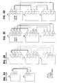
- Figs. 2A to 2D illustrate a series of phases involved when a new switching module is installed in a two-unit ATM switching system as shown in Fig. 2A.
- switching modules 10A and 10B are interconnected by an active link indicated by a thick line "A" terminating at both ends to active interfaces 3 and by a standby link indicated by a dotted line “S” terminating at both ends to standby interfaces 4.
- ATM cells transported across two switching modules are routed according to three physical addresses inserted respectively to PAO, PA1 and PA2 fields of their cell header.
- the physical address of a cell in the PAO field indicates an outgoing line port of the switching module to which the cell is directed
- the physical address of the cell in the PA1 field indicates routing information used by the second stage of the connection
- the physical address of the cell in the PA2 field indicates routing information used by the first stage of the connection.
- the PAO field contains no data
- the PA1 field contains data indicating an outgoing line port
- the PA2 field contains routing data to be used by the local ATM switch.
- a new switching module 10C is installed and new expansion interfaces are installed in the existing modules 10A and 10B.
- the system has expansion interfaces indicated by letters “a” to “1", with the interfaces "a” and “e” being interconnected by existing active link “A” and interfaces "b” and “f” being interconnected by existing standby link “S”. Cables are laid as standby links “S” between interfaces "c” and “k”, “d” and “I”, “g” and “I”, and "h” and "j".
- the switching module 1 OA functions as a master module and its processor takes the responsibility to perform a cutover operation.
- a cutover operation begins with step 30 where the master processor transmits a reconfiguration notification to modules 10B and 10C.
- the master processor sends an active/standby setting command from module 10A to new switching module 10C. This command message indicates the links to be set “active” or “standby” according to the system's maintenance plan.
- the processor sends a "hot-standby" command to modules 10B and 10A and proceeds to set its own expansion interfaces "b", "c", "d” in a hot-standby state.
- the processor at module 10-B sets its interfaces "f", "g", "h” in a hot-standby state and the processor at module 10C sets all of its expansion interfaces in a hot-standby state.
- the hot-standby state of an expansion interface is one in which the internal state of the interface is active and ready to accept ATM cells, but no connection is established from the ATM switch 1, while the active state is one in which the expansion interface is accepting flow of ATM traffic from the ATM switch 1 for processing.
- the processor at master module proceeds from step 34 to step 35 to send a backpressure-set command message to modules 10B and 10C in order to direct their extension interfaces, which are in the process of being switched over to active state, to apply a backpressure signal to their input port.
- "Backpressure" is used in the ATM switching technology when it is desired to exert a backward pressure on incoming traffic to prevent it from entering the ATM switch so that the switch is prevented from being overloaded.
- modules 10B and 10C When the switchover setting operation is completed at modules 10B and 10C, their processor returns a switchover complete message to the master module 10A.
- the master processor responds to the returning switchover complete messages at step 36 and proceeds to step 37 to send a backpressure-disconnect command to modules 10B and 10C to direct their switched active interfaces to disconnect the backpressure signal.
- the hold-off condition is released and the switched-over active expansion interfaces and their associated links accept traffic. In this manner, ATM cells within the ATM switch 1 are not corrupted or lost when the hot-standby links are switched over to active state.
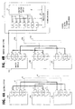
- FIGs. 4A through 4E A second embodiment of the present invention is shown in Figs. 4A through 4E.
- three existing basic switching modules 10A, 10B and 10C are interconnected to form a multistage network as shown in Fig. 4A in which links 41, 42, 43 are in standby state, interconnecting expansion interfaces "b" and "f", “d” and “j", and "f" and "l".
- a large-sized expansion switching module 11 is used for interconnecting the existing modules as illustrated in Fig. 4B.
- Expansion switching module 11 comprises a control interface 50, a plurality of expansion interfaces 51 through 56, an ATM switch 57 and a processor 58 whose function is similar to the processor of modules 10B and 10C.
- Control interface 50 is connected by an active link to the control interface 7 of the master module 10A.
- standby links are manually established by rewiring the existing standby links 41, 42 and 43 to the interfaces 52, 54 and 56 as new standby links 41A, 42A and 43A.
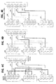
- a cutover operation of the laid-down standby links is initiated by the master processor according to the flowchart of Fig. 3.
- the master processor sends a system reconfiguration notification to all other switching modules including the expansion module 11 (step 30).
- the master processor sends an active/standby setting command to the expansion switching module 11.
- This command message indicates the links to be set “active” or “standby” according to the system's maintenance plan.
- the processor sends a "hot-standby" command to modules 10B, 10A and 11, and proceeds to set its own expansion interface "b" in hot-standby state.
- expansion interfaces "f” and “j” are set in a hot-standby state and corresponding interfaces 52, 54 and 56 of expansion module 11 are set in hot-standby mode.
- the processor at master module proceeds from step 34 to step 35 to send a backpressure-set command message to modules 10B, 10C, 11 in order to direct their extension interfaces to apply a backpressure signal to their input port.
- step 35 to send a backpressure-set command message to modules 10B, 10C, 11 in order to direct their extension interfaces to apply a backpressure signal to their input port.
- Fig. 4E shows the final stage of the system expansion.
- standby links 44, 45 and 46 are manually rewired and new standby links 44A, 45A and 46A are established to expansion units 51, 53 and 55 of the expansion module. Therefore, all inter module calls are routed through the expansion module 11.
- the physical address of a cell in the PAO field indicates routing information to be used by the third stage of the connection
- the physical address of the cell in the PA1 field indicates routing information to be used by the first stage of the connection
- the physical address of the cell in the PA2 field indicates routing information to be used by the second stage of the connection, i.e., the expansion module 11.
Landscapes
- Engineering & Computer Science (AREA)
- Computer Networks & Wireless Communication (AREA)
- Signal Processing (AREA)
- Data Exchanges In Wide-Area Networks (AREA)
- Use Of Switch Circuits For Exchanges And Methods Of Control Of Multiplex Exchanges (AREA)
Applications Claiming Priority (2)
| Application Number | Priority Date | Filing Date | Title |
|---|---|---|---|
| JP13904698 | 1998-05-20 | ||
| JP13904698A JP3001502B2 (ja) | 1998-05-20 | 1998-05-20 | Atmスイッチモジュール、atmスイッチ容量拡張方法、およびatmルーティング情報設定方法 |
Publications (1)
| Publication Number | Publication Date |
|---|---|
| EP0959591A1 true EP0959591A1 (de) | 1999-11-24 |
Family
ID=15236210
Family Applications (1)
| Application Number | Title | Priority Date | Filing Date |
|---|---|---|---|
| EP19990850088 Withdrawn EP0959591A1 (de) | 1998-05-20 | 1999-05-20 | ATM-Koppelfeldmodul zur Systemerweiterung ohne Zellenverlust |
Country Status (5)
| Country | Link |
|---|---|
| US (1) | US6459699B1 (de) |
| EP (1) | EP0959591A1 (de) |
| JP (1) | JP3001502B2 (de) |
| BR (1) | BR9902146A (de) |
| SE (1) | SE9901815D0 (de) |
Cited By (8)
| Publication number | Priority date | Publication date | Assignee | Title |
|---|---|---|---|---|
| WO2002013458A3 (en) * | 2000-08-07 | 2003-05-01 | Inrange Tech Corp | Fibre channel switch |
| US7042842B2 (en) | 2001-06-13 | 2006-05-09 | Computer Network Technology Corporation | Fiber channel switch |
| EP1501246A3 (de) * | 2003-04-25 | 2006-05-10 | Alcatel IP Networks, Inc. | Leitwegumlenkung von Netzwerkdaten |
| US7072298B2 (en) | 2001-06-13 | 2006-07-04 | Computer Network Technology Corporation | Method and apparatus for rendering a cell-based switch useful for frame based protocols |
| US7394814B2 (en) | 2001-06-13 | 2008-07-01 | Paul Harry V | Method and apparatus for rendering a cell-based switch useful for frame based application protocols |
| EP1298864A3 (de) * | 2001-09-27 | 2009-05-20 | Alcatel Canada Inc. | Einzelnes Brettnetzsystem erweiterbar zu einem mehrfachen Brettmodus |
| US7623519B2 (en) | 2004-06-21 | 2009-11-24 | Brocade Communication Systems, Inc. | Rule based routing in a switch |
| US7773622B2 (en) | 2001-12-19 | 2010-08-10 | Mcdata Services Corporation | Deferred queuing in a buffered switch |
Families Citing this family (15)
| Publication number | Priority date | Publication date | Assignee | Title |
|---|---|---|---|---|
| US7009977B1 (en) * | 2000-06-09 | 2006-03-07 | Conklin Corporation | Method and system for expanding services in a digital loop carrier system |
| US20020080780A1 (en) * | 2000-08-10 | 2002-06-27 | Mccormick James S. | Buffering system for use in a communication switch that includes a multiprocessor control block and method therefore |
| US7385965B2 (en) * | 2000-08-10 | 2008-06-10 | Alcatel-Lucent Canada Inc. | Multiprocessor control block for use in a communication switch and method therefore |
| US7269181B2 (en) * | 2001-04-04 | 2007-09-11 | Telefonaktiebolaget Lm Ericsson (Publ) | Robust radio base station controller architecture |
| JP2007503132A (ja) * | 2003-08-15 | 2007-02-15 | トムソン ライセンシング | マルチ拡張機能を有するブロードキャスト・ルータ |
| KR101069605B1 (ko) * | 2003-08-15 | 2011-10-05 | 톰슨 라이센싱 | 방송 라우터에서 변경가능한 기능 |
| BRPI0415404B1 (pt) * | 2003-10-14 | 2018-07-17 | Thomson Licensing | técnica para a adição de um ruído de conforto de bits exatos |
| CA2583156C (en) * | 2004-10-18 | 2014-03-18 | Thomson Licensing | Film grain simulation method |
| EP1813118B1 (de) * | 2004-11-12 | 2019-12-04 | InterDigital VC Holdings, Inc. | Filmkörnigkeitssimulation für normalwiedergabe und spezialwiedergabe für videowiedergabesysteme |
| KR101229942B1 (ko) | 2004-11-16 | 2013-02-06 | 톰슨 라이센싱 | 비디오 시스템에서 비트까지 정확한 시뮬레이션을 위한필름 그레인 sei 메시지 삽입 |
| WO2006055193A1 (en) | 2004-11-16 | 2006-05-26 | Thomson Licensing | Film grain simulation method based on pre-computed transform coefficients |
| ZA200703946B (en) | 2004-11-17 | 2008-08-27 | Thomson Licensing | Bit-accurate film grain simulation method based on pre-computed transformed coefficients |
| US8483288B2 (en) | 2004-11-22 | 2013-07-09 | Thomson Licensing | Methods, apparatus and system for film grain cache splitting for film grain simulation |
| US10715834B2 (en) | 2007-05-10 | 2020-07-14 | Interdigital Vc Holdings, Inc. | Film grain simulation based on pre-computed transform coefficients |
| CN101645750B (zh) * | 2009-09-02 | 2013-09-11 | 中兴通讯股份有限公司 | 分布式电交叉装置实现snc级联保护的系统和方法 |
Citations (2)
| Publication number | Priority date | Publication date | Assignee | Title |
|---|---|---|---|---|
| WO1995030318A2 (en) * | 1994-04-29 | 1995-11-09 | Newbridge Networks Corporation | Atm switching system |
| EP0785698A2 (de) * | 1996-01-16 | 1997-07-23 | AT&T Corp. | Puffer von Mehrfachsendezellen in Vermittlungsnetzen |
Family Cites Families (9)
| Publication number | Priority date | Publication date | Assignee | Title |
|---|---|---|---|---|
| JPH04273739A (ja) | 1991-02-28 | 1992-09-29 | Nec Corp | 単位スイッチモジュール及びそれを用いたatmクロスコネクト装置 |
| JPH05167603A (ja) | 1991-12-12 | 1993-07-02 | Nec Commun Syst Ltd | 広帯域isdn端末アダプタ装置 |
| JPH05308687A (ja) | 1992-04-28 | 1993-11-19 | Fujitsu Ltd | 回線交換装置のタイムスイッチ容量の拡張方式 |
| JPH06141038A (ja) | 1992-10-26 | 1994-05-20 | Hitachi Ltd | 分散交換機及び交換機構成方式 |
| JPH07115421A (ja) | 1993-10-19 | 1995-05-02 | Toshiba Corp | Atm交換機 |
| JP3549224B2 (ja) | 1993-11-17 | 2004-08-04 | 富士通株式会社 | Atmスイッチ装置 |
| JP3291122B2 (ja) | 1994-06-02 | 2002-06-10 | 富士通株式会社 | 自己ルーチング交換機、atm交換機及び交換システム |
| JPH08265328A (ja) * | 1995-03-20 | 1996-10-11 | Fujitsu Ltd | 多段接続スイッチおよびその増設方法 |
| US5909427A (en) * | 1995-07-19 | 1999-06-01 | Fujitsu Network Communications, Inc. | Redundant switch system and method of operation |
-
1998
- 1998-05-20 JP JP13904698A patent/JP3001502B2/ja not_active Expired - Fee Related
-
1999
- 1999-05-19 SE SE9901815A patent/SE9901815D0/xx unknown
- 1999-05-20 US US09/316,114 patent/US6459699B1/en not_active Expired - Fee Related
- 1999-05-20 EP EP19990850088 patent/EP0959591A1/de not_active Withdrawn
- 1999-05-20 BR BR9902146A patent/BR9902146A/pt not_active IP Right Cessation
Patent Citations (2)
| Publication number | Priority date | Publication date | Assignee | Title |
|---|---|---|---|---|
| WO1995030318A2 (en) * | 1994-04-29 | 1995-11-09 | Newbridge Networks Corporation | Atm switching system |
| EP0785698A2 (de) * | 1996-01-16 | 1997-07-23 | AT&T Corp. | Puffer von Mehrfachsendezellen in Vermittlungsnetzen |
Non-Patent Citations (1)
| Title |
|---|
| FISCHER W ET AL: "A SCALABLE ATM SWITCHING SYSTEM ARCHITECTURE", IEEE JOURNAL ON SELECTED AREAS IN COMMUNICATIONS, vol. 9, no. 8, 1 October 1991 (1991-10-01), pages 1299 - 1307, XP000267581, ISSN: 0733-8716 * |
Cited By (13)
| Publication number | Priority date | Publication date | Assignee | Title |
|---|---|---|---|---|
| WO2002013458A3 (en) * | 2000-08-07 | 2003-05-01 | Inrange Tech Corp | Fibre channel switch |
| US6895528B2 (en) | 2000-08-07 | 2005-05-17 | Computer Network Technology Corporation | Method and apparatus for imparting fault tolerance in a switch or the like |
| US6981078B2 (en) | 2000-08-07 | 2005-12-27 | Computer Network Technology Corporation | Fiber channel architecture |
| US7394814B2 (en) | 2001-06-13 | 2008-07-01 | Paul Harry V | Method and apparatus for rendering a cell-based switch useful for frame based application protocols |
| US7072298B2 (en) | 2001-06-13 | 2006-07-04 | Computer Network Technology Corporation | Method and apparatus for rendering a cell-based switch useful for frame based protocols |
| US7042842B2 (en) | 2001-06-13 | 2006-05-09 | Computer Network Technology Corporation | Fiber channel switch |
| EP1298864A3 (de) * | 2001-09-27 | 2009-05-20 | Alcatel Canada Inc. | Einzelnes Brettnetzsystem erweiterbar zu einem mehrfachen Brettmodus |
| US7773622B2 (en) | 2001-12-19 | 2010-08-10 | Mcdata Services Corporation | Deferred queuing in a buffered switch |
| US8379658B2 (en) | 2001-12-19 | 2013-02-19 | Brocade Communications Systems, Inc. | Deferred queuing in a buffered switch |
| EP1501246A3 (de) * | 2003-04-25 | 2006-05-10 | Alcatel IP Networks, Inc. | Leitwegumlenkung von Netzwerkdaten |
| US7660239B2 (en) | 2003-04-25 | 2010-02-09 | Alcatel-Lucent Usa Inc. | Network data re-routing |
| CN1571417B (zh) * | 2003-04-25 | 2011-06-29 | 阿尔卡特Ip网络有限公司 | 网络数据重新路由 |
| US7623519B2 (en) | 2004-06-21 | 2009-11-24 | Brocade Communication Systems, Inc. | Rule based routing in a switch |
Also Published As
| Publication number | Publication date |
|---|---|
| JPH11331202A (ja) | 1999-11-30 |
| BR9902146A (pt) | 2000-02-01 |
| US6459699B1 (en) | 2002-10-01 |
| JP3001502B2 (ja) | 2000-01-24 |
| SE9901815D0 (sv) | 1999-05-19 |
Similar Documents
| Publication | Publication Date | Title |
|---|---|---|
| US6459699B1 (en) | ATM switching module which allows system growth with different type of module without cell-loss during cutover | |
| US5777994A (en) | ATM switch and intermediate system | |
| EP0449095B1 (de) | Steuerungsvorrichtung zur Lastverteilung auf Anrufbehandlungseinheiten | |
| US5771231A (en) | ATM exchange | |
| EP0494170B1 (de) | Schaltknoten für ein kommunikationsschaltnetz | |
| JP2892689B2 (ja) | パケット通信網およびパケット交換機 | |
| JP2972257B2 (ja) | パケット交換機 | |
| US5408472A (en) | Device and method for cell processing in cell relay nodes | |
| US6240090B1 (en) | Self-configuring processors in an asynchronous transfer mode switch | |
| JPH10285187A (ja) | Atmスイッチ用の分散形バッファリング・システム | |
| Hajikano et al. | Asynchronous transfer mode switching architecture for broadband ISDN-multistage self-routing switching (MSSR) | |
| US6618372B1 (en) | Packet switching system having-having self-routing switches | |
| US5748632A (en) | ATM switching apparatus | |
| EP0734188B1 (de) | Mehrstufige Vermittlungseinrichtung | |
| SE511581C2 (sv) | System och förfarande för ATM-koppling av en telefonförbindelse | |
| JP3373281B2 (ja) | ローカルネットワーク | |
| JP2927465B2 (ja) | 分散型交換モジュール間結合方式 | |
| US5434851A (en) | Digital telecommunications switching system | |
| US7058062B2 (en) | Packet switching system having self-routing switches | |
| WO1996029799A1 (en) | Packet terminal and packet communication network | |
| JPH07101888B2 (ja) | 交換装置によるlan間接続方式 | |
| KR100237396B1 (ko) | 비동기 전송모드 교환 시스템을 위한 중앙집중 경로제어 방법 | |
| JP3059102B2 (ja) | Atm交換機 | |
| JP3070545B2 (ja) | パケット通信網及びパケット交換機 | |
| KR100456676B1 (ko) | 비동기식 전달 모드 교환 시스템에서의 연결식별자 연동장치 및 방법 |
Legal Events
| Date | Code | Title | Description |
|---|---|---|---|
| PUAI | Public reference made under article 153(3) epc to a published international application that has entered the european phase |
Free format text: ORIGINAL CODE: 0009012 |
|
| AK | Designated contracting states |
Kind code of ref document: A1 Designated state(s): ES SE |
|
| AX | Request for extension of the european patent |
Free format text: AL;LT;LV;MK;RO;SI |
|
| 17P | Request for examination filed |
Effective date: 19991022 |
|
| AKX | Designation fees paid |
Free format text: ES SE |
|
| REG | Reference to a national code |
Ref country code: DE Ref legal event code: 8566 |
|
| 17Q | First examination report despatched |
Effective date: 20011116 |
|
| STAA | Information on the status of an ep patent application or granted ep patent |
Free format text: STATUS: THE APPLICATION HAS BEEN WITHDRAWN |
|
| 18W | Application withdrawn |
Withdrawal date: 20020304 |