EP0959508A1 - Dispositif interrupteur de courant en particulier pour utilisation dans des piles électrochimiques prismatiques - Google Patents
Dispositif interrupteur de courant en particulier pour utilisation dans des piles électrochimiques prismatiques Download PDFInfo
- Publication number
- EP0959508A1 EP0959508A1 EP99303912A EP99303912A EP0959508A1 EP 0959508 A1 EP0959508 A1 EP 0959508A1 EP 99303912 A EP99303912 A EP 99303912A EP 99303912 A EP99303912 A EP 99303912A EP 0959508 A1 EP0959508 A1 EP 0959508A1
- Authority
- EP
- European Patent Office
- Prior art keywords
- cup
- side wall
- housing
- support
- aperture
- Prior art date
- Legal status (The legal status is an assumption and is not a legal conclusion. Google has not performed a legal analysis and makes no representation as to the accuracy of the status listed.)
- Withdrawn
Links
- 239000012528 membrane Substances 0.000 claims abstract description 37
- 239000002131 composite material Substances 0.000 claims abstract description 20
- 239000000463 material Substances 0.000 claims description 48
- 238000012546 transfer Methods 0.000 claims description 14
- 238000003466 welding Methods 0.000 claims description 13
- 239000012530 fluid Substances 0.000 claims description 7
- 238000000034 method Methods 0.000 claims description 3
- 239000004020 conductor Substances 0.000 claims description 2
- 238000002788 crimping Methods 0.000 claims description 2
- 238000007789 sealing Methods 0.000 claims description 2
- 229910052782 aluminium Inorganic materials 0.000 description 15
- XAGFODPZIPBFFR-UHFFFAOYSA-N aluminium Chemical compound [Al] XAGFODPZIPBFFR-UHFFFAOYSA-N 0.000 description 13
- PXHVJJICTQNCMI-UHFFFAOYSA-N nickel Substances [Ni] PXHVJJICTQNCMI-UHFFFAOYSA-N 0.000 description 12
- 229910052759 nickel Inorganic materials 0.000 description 8
- 239000003792 electrolyte Substances 0.000 description 7
- 230000007246 mechanism Effects 0.000 description 7
- 238000013519 translation Methods 0.000 description 7
- 239000010960 cold rolled steel Substances 0.000 description 6
- 229910052802 copper Inorganic materials 0.000 description 5
- 239000010949 copper Substances 0.000 description 5
- 239000012212 insulator Substances 0.000 description 4
- 229910001416 lithium ion Inorganic materials 0.000 description 4
- 230000004048 modification Effects 0.000 description 4
- 238000012986 modification Methods 0.000 description 4
- HLXZNVUGXRDIFK-UHFFFAOYSA-N nickel titanium Chemical compound [Ti].[Ti].[Ti].[Ti].[Ti].[Ti].[Ti].[Ti].[Ti].[Ti].[Ti].[Ni].[Ni].[Ni].[Ni].[Ni].[Ni].[Ni].[Ni].[Ni].[Ni].[Ni].[Ni].[Ni].[Ni] HLXZNVUGXRDIFK-UHFFFAOYSA-N 0.000 description 4
- 229910001000 nickel titanium Inorganic materials 0.000 description 4
- 239000000615 nonconductor Substances 0.000 description 4
- RYGMFSIKBFXOCR-UHFFFAOYSA-N Copper Chemical compound [Cu] RYGMFSIKBFXOCR-UHFFFAOYSA-N 0.000 description 3
- 239000004677 Nylon Substances 0.000 description 3
- 239000004743 Polypropylene Substances 0.000 description 3
- 229910000831 Steel Inorganic materials 0.000 description 3
- 230000009471 action Effects 0.000 description 3
- 230000003247 decreasing effect Effects 0.000 description 3
- 238000006073 displacement reaction Methods 0.000 description 3
- 230000006870 function Effects 0.000 description 3
- 238000010438 heat treatment Methods 0.000 description 3
- 229920001778 nylon Polymers 0.000 description 3
- -1 polypropylene Polymers 0.000 description 3
- 229920001155 polypropylene Polymers 0.000 description 3
- 230000004044 response Effects 0.000 description 3
- 239000010959 steel Substances 0.000 description 3
- 230000007704 transition Effects 0.000 description 3
- WHXSMMKQMYFTQS-UHFFFAOYSA-N Lithium Chemical compound [Li] WHXSMMKQMYFTQS-UHFFFAOYSA-N 0.000 description 2
- 230000002411 adverse Effects 0.000 description 2
- 230000008859 change Effects 0.000 description 2
- 230000003993 interaction Effects 0.000 description 2
- 238000002955 isolation Methods 0.000 description 2
- 229910052744 lithium Inorganic materials 0.000 description 2
- 230000002093 peripheral effect Effects 0.000 description 2
- HBBGRARXTFLTSG-UHFFFAOYSA-N Lithium ion Chemical compound [Li+] HBBGRARXTFLTSG-UHFFFAOYSA-N 0.000 description 1
- 239000004820 Pressure-sensitive adhesive Substances 0.000 description 1
- 239000011149 active material Substances 0.000 description 1
- 238000005452 bending Methods 0.000 description 1
- 230000008901 benefit Effects 0.000 description 1
- DMFGNRRURHSENX-UHFFFAOYSA-N beryllium copper Chemical compound [Be].[Cu] DMFGNRRURHSENX-UHFFFAOYSA-N 0.000 description 1
- 238000006243 chemical reaction Methods 0.000 description 1
- 238000004891 communication Methods 0.000 description 1
- 230000006835 compression Effects 0.000 description 1
- 238000007906 compression Methods 0.000 description 1
- 229920001940 conductive polymer Polymers 0.000 description 1
- 238000013270 controlled release Methods 0.000 description 1
- 238000005520 cutting process Methods 0.000 description 1
- 238000007599 discharging Methods 0.000 description 1
- 230000000694 effects Effects 0.000 description 1
- 238000005530 etching Methods 0.000 description 1
- 238000004880 explosion Methods 0.000 description 1
- 239000011521 glass Substances 0.000 description 1
- PCHJSUWPFVWCPO-UHFFFAOYSA-N gold Chemical compound [Au] PCHJSUWPFVWCPO-UHFFFAOYSA-N 0.000 description 1
- 229910052737 gold Inorganic materials 0.000 description 1
- 239000010931 gold Substances 0.000 description 1
- 229910052751 metal Inorganic materials 0.000 description 1
- 239000002184 metal Substances 0.000 description 1
- 238000000465 moulding Methods 0.000 description 1
- 238000013021 overheating Methods 0.000 description 1
- 229920000642 polymer Polymers 0.000 description 1
- 238000000926 separation method Methods 0.000 description 1
- 229910052709 silver Inorganic materials 0.000 description 1
- 239000004332 silver Substances 0.000 description 1
- 239000007787 solid Substances 0.000 description 1
- 239000002904 solvent Substances 0.000 description 1
- 239000010935 stainless steel Substances 0.000 description 1
- 229910001220 stainless steel Inorganic materials 0.000 description 1
- 238000005728 strengthening Methods 0.000 description 1
- 238000013022 venting Methods 0.000 description 1
- 238000005406 washing Methods 0.000 description 1
Images


Classifications
-
- H—ELECTRICITY
- H01—ELECTRIC ELEMENTS
- H01M—PROCESSES OR MEANS, e.g. BATTERIES, FOR THE DIRECT CONVERSION OF CHEMICAL ENERGY INTO ELECTRICAL ENERGY
- H01M50/00—Constructional details or processes of manufacture of the non-active parts of electrochemical cells other than fuel cells, e.g. hybrid cells
- H01M50/10—Primary casings; Jackets or wrappings
- H01M50/147—Lids or covers
- H01M50/166—Lids or covers characterised by the methods of assembling casings with lids
- H01M50/169—Lids or covers characterised by the methods of assembling casings with lids by welding, brazing or soldering
-
- H—ELECTRICITY
- H01—ELECTRIC ELEMENTS
- H01M—PROCESSES OR MEANS, e.g. BATTERIES, FOR THE DIRECT CONVERSION OF CHEMICAL ENERGY INTO ELECTRICAL ENERGY
- H01M50/00—Constructional details or processes of manufacture of the non-active parts of electrochemical cells other than fuel cells, e.g. hybrid cells
- H01M50/30—Arrangements for facilitating escape of gases
- H01M50/342—Non-re-sealable arrangements
-
- H—ELECTRICITY
- H01—ELECTRIC ELEMENTS
- H01M—PROCESSES OR MEANS, e.g. BATTERIES, FOR THE DIRECT CONVERSION OF CHEMICAL ENERGY INTO ELECTRICAL ENERGY
- H01M50/00—Constructional details or processes of manufacture of the non-active parts of electrochemical cells other than fuel cells, e.g. hybrid cells
- H01M50/50—Current conducting connections for cells or batteries
- H01M50/572—Means for preventing undesired use or discharge
- H01M50/574—Devices or arrangements for the interruption of current
-
- H—ELECTRICITY
- H01—ELECTRIC ELEMENTS
- H01M—PROCESSES OR MEANS, e.g. BATTERIES, FOR THE DIRECT CONVERSION OF CHEMICAL ENERGY INTO ELECTRICAL ENERGY
- H01M50/00—Constructional details or processes of manufacture of the non-active parts of electrochemical cells other than fuel cells, e.g. hybrid cells
- H01M50/30—Arrangements for facilitating escape of gases
- H01M50/342—Non-re-sealable arrangements
- H01M50/3425—Non-re-sealable arrangements in the form of rupturable membranes or weakened parts, e.g. pierced with the aid of a sharp member
-
- Y—GENERAL TAGGING OF NEW TECHNOLOGICAL DEVELOPMENTS; GENERAL TAGGING OF CROSS-SECTIONAL TECHNOLOGIES SPANNING OVER SEVERAL SECTIONS OF THE IPC; TECHNICAL SUBJECTS COVERED BY FORMER USPC CROSS-REFERENCE ART COLLECTIONS [XRACs] AND DIGESTS
- Y02—TECHNOLOGIES OR APPLICATIONS FOR MITIGATION OR ADAPTATION AGAINST CLIMATE CHANGE
- Y02E—REDUCTION OF GREENHOUSE GAS [GHG] EMISSIONS, RELATED TO ENERGY GENERATION, TRANSMISSION OR DISTRIBUTION
- Y02E60/00—Enabling technologies; Technologies with a potential or indirect contribution to GHG emissions mitigation
- Y02E60/10—Energy storage using batteries
Definitions
- This invention relates generally to electrochemical cells and more particularly to current interrupt apparatus for use with prismatic electrochemical cells responsive to selected adverse conditions.
- Electrochemical cells are subject to leakage or rupture as a result of various abusive treatment, which in turn, can cause damage to a device which is powered by the cell or to the surrounding environment. Such cells are sealed to prevent egress of electrolyte solvent and ingress of moisture from the exterior environment.
- abusive treatment include charging at too rapid a rate, overcharging above a specified maximum voltage or discharging below a specified minimum cell voltage which can lead to an increase in temperature and/or pressure.
- an exothermic reaction begins which leads to overheating and causes a build-up in pressure which may result in expulsion of electrolyte from the cell.
- a pressure driven current interrupt device to terminate current flow under adverse charge or discharge conditions.
- a thin metallic diaphragm eg., formed of aluminum, mounted in a header of the cell and exposed to pressure generated in the cell is attached to a pressure plate at the central axis, as by laser or ultrasonic welding, with an electrical insulator sandwiched therebetween.
- pressure increases stress is created at the welded interface with the weld joint fracturing at a selected pressure range allowing the diaphragm to translate away from the plate to permanently open the electric circuit and terminate current flow.
- the diaphragm is formed with a reduced thickness portion, e.g., a C-shaped groove extending along the peripheral edge of the diaphragm so that the diaphragm ruptures at a calibrated predetermined pressure to allow controlled venting of pressurized electrolyte.
- a current interrupt device of this type is shown in U.S. Patent No. 5,691,073.
- the above descnbed end cap and current interrupt device assembly can be used conveniently in cylindrical electrochemical cells typically having diameters of 17mm or more.
- the available membrane surface used to drive the pressure current interrupt device is reduced so that with prismatic cells having a thickness of only 10mm, 8mm or 6mm, for example, the diameter of the working portion of the diaphragm is too small to provide sufficient translation to fracture the welded joint with the pressure plate so that a different operational mechanism is needed to provide the current interrupt function.
- the prevalent header related safety feature currently in commercial use is a pressure vent which allows controlled release of pressurized electrolyte in order to prevent cell explosion.
- an annular header adapted to be attached in fluid sealing relation to a cover of an electrochemical cell, mounts a generally cup-shaped member having a generally flat, relatively stiff end wall and a cylindrical side wall extending in a direction from the end wall toward the exterior of the cell with a free end of the side wall attached to the header and with the flat stiff end wall exposed to the pressurized fluid in the cell.
- the cup-shaped member is formed of electrically conductive material and in this embodiment and several others forms part of the current path between one of the plates of the core of the cell through a strap welded to the cup-shaped member and a top cap mounted on the header.
- the cup-shaped member may advantageously be formed of aluminum with side walls formed to catastrophically collapse/buckle with a sudden or snap action movement at a specific pressure level due to axial and moment stress created by internal cell pressure.
- a reduced thickness groove preferably generally circular in shape, and a transition section connecting the side wall and the groove is used to aid in achieving low pressure actuation protection and/or to provide calibration of the pressure level at which the side wall collapse occurs by controlling the effective length of the moment arm of the applied stress to the side wall to offset material geometry and variations in material properties.
- calibration for variations in material geometry and properties can be provided by changing the intemal radius between the side and end walls to effectively change the moment arm.
- the instantaneous, catastrophic collapsing motion is used in one preferred embodiment to fracture a welded joint between the end wall and a pressure plate to interrupt the current path.
- the collapsing motion is used to move an electrical insulator to permanently open a spring loaded electrical contact interface in one embodiment and to fracture welded electrical contact interface disposed extemally of the casing of the cell in another embodiment.
- single action short circuit protection can be provided in certain embodiments by using spring material having thermal memory, such as Nitinol, or thermostat metal which revert back to a calibrated, open contact configuration upon sufficient I 2 r heating.
- spring material having thermal memory such as Nitinol, or thermostat metal which revert back to a calibrated, open contact configuration upon sufficient I 2 r heating.
- Yet another modified embodiment employs a positive temperature coefficient of resistivity element for short circuit protection.
- a current interrupt device which is crimped to a cover assembly which in turn is welded to the side wall of the electrochemical cell.
- Another embodiment includes a composite cover comprising a membrane or sheet layer which is essentially co-extensive with a support layer in which both a pressure vent and a current interrupt device is incorporated with the composite cover and membrane crimped to the side wall of the cell.
- Still other embodiments show a composite cover provided with both a pressure vent and current interrupt device in which the composite is welded to the side wall of the cell. In the latter embodiments a separate terminal is mounted through an aperture formed in and electrically isolated from the composite.
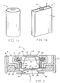
- a typical cylindrical electrochemical cell 2 is shown. Since the end faces of cell 2 are circular, essentially the entire area can be used to accommodate an appropriate safety mechanism such as those shown in copending U.S. Provisional Application No. 60/071, 557, filed 01/15/98 or U.S. Patent No. 5,691,073, referenced supra.
- Such safety mechanisms are characterized in having a flexible diaphragm exposed to the fluid within the cell which bulges upon a selected increase in pressure creating sufficient stress to fracture a welded joint of the diaphragm and a pressure plate and to provide sufficient translation to break a current path, either directly or through a motion transfer member.
- a prismatic electrochemical cell such as cell 4 shown in Fig.
- the working diameter available for a diaphragm is limited by the thickness of the cell so that insufficient translational movement is obtainable in small prismatic cells to effectively use the teachings of the above noted safety mechanisms.
- protection located in the header for small prismatic cells has been limited to forming a pressure vent (not shown) in cover 8 without interrupting the current path between the terminals comprising a thin membrane received over an aperture in the cover and rupturable at some specified pressure level.
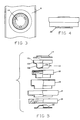
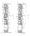
- FIGs. 2-5 show a current interrupt device 10 made in accordance with a first embodiment of the invention, especially adapted for use in small prismatic cells, although useable in other applications as well.
- Current interrupt device 10 comprises a cup-shaped member 12 having a generally flat bottom wall 12a and side wall 12b extending upwardly, i.e., in a direction away from the interior of the cell, as seen in the drawings, to a radially extending flange 12c. Stated in another way, the side wall of the cup-shaped member extends from its mounting location, in a direction toward the interior of the cell.
- Cup member 12 is formed with side wall 12b and end wall 12a forming an interior angle preferably greater than 90° to facilitate having the force generated by pressure generated in the cell to act on the side wall through a controlled moment arm utilizing end wall 12a to be discussed.
- Flange 12c is crimped onto a top cap terminal plate 14 by a crimp ring 16 with an electrically insulative sleeve 18 interposed therebetween to electrically isolate terminal plate 14 and cup-shaped member 12 from crimp ring 16 and cover 8 and to provide an electrolyte seal. As shown (see Fig.
- flange 12c is advantageously formed with an extended, upwardly formed free end portion 12d to be folded over onto the top surface of the outer flange 14a of terminal plate 14 to provide an extended seal path without sharp edges. That is, the possibility of a sharp blanking burr on terminal plate 14 cutting through the polymer seal 18 is obviated.
- Crimp ring 16 is received in an opening of cover 8 of prismatic cell 4 formed by downwardly extending wall portion 8a and hermetically attached thereto as by laser welding around the perimeter of wall portion 8a. Cover 8 is in turn hermetically attached to side wall 6 of the cell as by laser welding an upper wall portion 8b thereto.
- An electrically conductive plate 22 is attached to the center portion of bottom wall 12a, as by laser or ultrasonic welding, which in turn is welded to an electrode tab 24 from the core of the cell.
- An electrical insulator member 26 having an aperture 26a is disposed intermediate to cover 8, crimp ring 16 and plate 22 to maintain electrical isolation between cover 8, crimp ring 16 and plate 22 and to limit translation of plate 22 in the case of actuation of the current interrupt device to be discussed below. If desired, insulator member 26 could be eliminated by extending vertical wall portion 18b of sleeve 18 toward plate 22 and between the outer portion of plate 22 and the cup member surface.
- top cap terminal plate 14 along with crimp ring 16, supports an electrolyte seal in the form of sleeve 18 of suitable material such as polypropylene.
- Plate 14 serves as a positive or negative electrode of the cell and forms part of the current path.
- Terminal plate 14 is formed with an offset central portion 14b which provides a cavity for collapse and inversion of cup member 12 while vent holes formed through plate 14 allow air volume displacement during such collapse.
- Plate 22 is preferably formed with a reduced thickness center portion 22a of approximately the same thickness as that of end wall 12a as in aid in providing a good laser or ultrasonic weld joint with wall 12a of cup member 12.
- a frusto-conical section 22b provides a selected gap between outer peripheral flange 22c allowing for creep displacement of the cup member prior to the collapse of the side wall 12b. This ensures calibrated actuation of the current interrupt device and impact loading of the electrical interface to open the circuit. Holes (not shown) are formed in plate 22 to allow pressurization of the cup member.
- the current interrupt device can be used with a positive or negative core polarity as desired.
- positive core polarity for a lithium ion cell
- suitable materials include: terminal plate 14 - nickel plated cold rolled steel AISI 1008 1008; cup member 12 - 3003 aluminum; sleeve 18 - polypropylene; crimp ring 16 - nickel plated cold rolled steel AISI 1008; Cover 8- nickel plated cold rolled steel AISI 1008; insulative member 26 - Nylon; and plate 22 - 3003 aluminum.
- suitable materials include: terminal plate 14 - nickel plated cold rolled steel AISI 1008; cup member 12 - copper CDA C10500; sleeve 18 - polypropylene; crimp ring 16 - aluminum 3003; cover 8 - aluminum 3003; insulative member 26 - Nylon; and plate 22 - copper CDA C10500.
- Cup-shaped member 12 is formed from material having a selected diameter, ultimate strength and wall thickness so that when intemal pressure generated within cell 4 increases, side wall 12b is unable to support the load placed on it once the force exerted on the side wall exceeds the material's ultimate strength at which point the side wall catastrophically collapses with end wall 12a, generally maintaining its flat configuration, translating toward terminal plate 14 with the end wall staying in a plane generally parallel to the plane in which the cover lies and the cup-shaped member going into an inverted structure as shown in dashed lines 12d.
- Side wall 12b of suitable material such as drawn aluminum or copper collapses at a specific pressure level due to axial and moment stress created by intemal cell pressure.
- wall 12a creates stress at the welded interface with plate 22 constrained by insulator member 26 causing the weld joint to fracture at a specified pressure range allowing the side and end walls to translate away from plate 22 thereby permanently opening the electrical circuit and terminating any current flow.
- the particular length of side wall 12b is selected based on the amount of vertical translation desired.
- end wall 12a and side wall 12b are joined together by a curved surface of radius R.
- a circular groove 12e of selected diameter of reduced thickness is formed in the bottom wall by etching, coining or the like. i.e.. the groove is formed a selected distance from side wall 12b with a transition section 12g extending between the radius R in side wall 12b and the location of groove 12e.
- cup-shaped member 12 and plate 22 may be a combination of side wall and transition section collapse/buckle.
- the diameter of groove 12e and the radius R interact with each other to provide means for calibrated actuation of the side wall collapse.
- two groups of cup-shaped members formed of aluminum having a material thickness of 0.004 inch and a side wall 12a diameter of 0.150 inch were submitted to increasing pressure to simulate the intemal pressure of an electrochemical cell.
- One group had a radius R of 0.03 inch (line a) while the second group had a radius R of 0.015 inch (line b).
- end wall 12a' of cup-shaped member 12 v can also be formed with a vertically offset circular central portion 12f, preferably offset downwardly as viewed in the figure.
- the term "generally flat end wall” is used to describe this modification as well as end wall 12a since the configuration of both end walls 12a and 12a' remains generally unchanged before and after collapse of the side wall of the cup-shaped member upon overpressure.
- the diameter of the offset portion of end wall 12a' relative to the diameter of the side wall will impact the effective length of the moment arm.
- the specific angle formed between the plane of the end wall 12a and side wall 12b can be used as a calibration factor.
- the actuation pressure (P) of the collapse is influenced by several physical factors.
- a defined material selection e.g., aluminum, copper, steel, nickel
- the pressure which promotes collapse of the side wall is decreased as the outside diameter (D 1 ) of the cup-shaped member is increased, material thickness (t) is decreased, ultimate tensile strength (UTS) is decreased, offset diameter (D 2 ) is increased, and the manipulation of an interaction between the coin diameter (D 3 ) and radius (R) is selected for optimum performance.
- the interaction between diameter D 3 and radius R can be used as a calibration feature to adjust for normal in specification variation of material thickness, material structural properties, and form tool wear thereby centering the actuation pressure to application specifications.
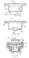
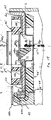
- Fig. 6 shows a modified embodiment in which an actuator pin 27 is slidably mounted in a bore 28a of an electrically conductive support plate 28 and is adapted to transfer motion from bottom wall 12a to an electrical contact portion 30 of an electrically conductive spring member 32 to move contact portion 30 out of electrical engagement with support plate 28 when side wall 12b of cup member 12" collapses due to a pressure increase above a predetermined level, as explained above, to provide a non-resettable current interrupt device.
- a suitable electrically insulative gasket 34 separates terminal plate 14' and spring member 32 from support plate 28.
- spring member 32 can be formed of material having thermal memory, such as Nitinol, to provide a current interrupt device which responds to short circuit conditions.
- spring member 32 can be formed of beryllium copper or other suitable material to provide a pressure actuated current interrupt function only. It will be understood that in either alternative the contact interface surfaces may be plated with gold, silver or the like to reduce interface resistance.
- Pressure sensitive adhesive tape 36 may be disposed on top of terminal plate 14' covering hole 14a for use when washing the cell after its assembly and prior to use.
- Figs. 7 and 7a show another altemate embodiment 10" similar to the Fig. 6 embodiment except that the functions of the actuator pin and the gasket are combined into a singled molded insulative actuator member 40 which has a cantilever arm 40a formed with a bore 40b which receives stationary contact 28a of support plate 28' therethrough. Arm 40a is formed with a hinge portion 40c comprising a reduced thickness groove to allow arm 40a to pivot in response to an upward force placed on actuator portion 40d which depends from the distal free end of arm 40a through an aperture 28b in support plate 28' into the chamber formed by side wall 12b and end wall 12a.
- spring member 32 can be formed of thermal memory material such as Nitinol to provide current interruption in response to short circuit conditions or conventional spring material to provide current interruption only in response to pressure.
- Figs. 8 and 8a show another alternate embodiment similar to Figs. 6 and 7.
- actuator member 40' is formed with transversely extending spiral arms 40a' to provide extended flexible vertical translation.
- a pair of actuator members 40d' depend downwardly from central ring portion 40e and serve the same purpose as actuator member 40d of Fig. 7.
- the above described embodiments relate to current interrupt devices or safety headers which are welded to the cover of a cell.
- the following embodiments relate to cell covers which integrate a current interrupt device and a pressure vent with the integrated covers either crimped or welded to the cell casing.
- Figs. 9-11 show modified embodiments suitable for use with a cover plate of the type which is attached to the cell housing by crimping through an insulative seal member.
- cup member 12 IV can be mounted directly to the cover which serves as a support, as shown in Figs. 9-11 by laser welding or the like to form a hermetic seal.
- the cover member could be formed of clad material such as stainless steel/aluminum as shown by cover member 8' of Fig. 9 and 8"' of Fig. 11 or it could be formed of a solid piece of suitable material such as aluminum as shown by cover 8" of Fig. 10.
- a vertically raised offset 8c or a piece of cold rolled steel 8c' or the like of Fig. 10 can serve as a convenient feature for making electrical connection.
- Figs. 12 and 12a show another modification of a current interrupt device adapted for use with electrochemical cells having a crimped cover.
- Current interrupt device 10 VII shown in Fig. 12 combines a crimp connected composite cover 8 IV comprising a support layer and underlying membrane or sheet having a current interrupt cup-shaped member 12 VI integrally formed with a pressure vent 12g in which the membrane forms part of the current path of the electrochemical cell.
- Cup-shaped member 12 VI and pressure vent 12g are formed from a sheet 12h of suitable material such as aluminum or copper depending upon the intended polarity of the cover as discussed above.
- Pressure vent 12g is preferably formed with a reduced thickness portion, such as a coined portion 12j, to facilitate rupture when subjected to a predetermined pressure.
- FIG. 12a shows coined portion 12j in the general form of an I beam.
- Another optimized configuration (not shown) for coined portion 12j follows the perimeter of aperture 8c, slightly inboard thereof, aperture 8c formed in a support layer of cover 8 IV to be discussed.
- the support layer of cover 8 IV formed of suitable material such as nickel plated cold rolled steel, has an aperture 8c aligned with pressure vent 12g and a downwardly extending wall portion 8d to prevent upward movement of sheet 12h beyond the perimeter of the pressure vent area.
- the support layer of cover 8 IV has an aperture 8e in communication with cup-shaped member 12 VI to allow air displacement in the event of actuation of cup-shaped member 12 VI , i.e., collapse of side wall 12b and which can also be used to place other current interrupt mechanisms as discussed above.
- Cover 8 IV is also advantageously formed with an upwardly extending offset portion 8f to facilitate electrical connection to the cover and serves as one of the terminals of the electrochemical cell.
- the support layer of cover 8 IV and membrane 12h are crimped to side wall 6' through an electrically insulative gasket 30 which also serves as an electrolyte seal. Although a separate electrical insulator 26" is shown, it can be combined into a single component with gasket 30, if desired.
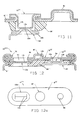
- Figs. 13,13a, 13b, 14 and 14a show other embodiments in which a composite cover having a support layer and a generally co-extensive membrane layer are used which include both a pressure vent and a current interrupt member in which one of the terminals of the electrochemical cell is mounted in an aperture formed in the support and membrane layers and is electrically isolated therefrom.
- a current interrupt device 10 VIII having a composite cover 8 V comprising support layer 8g formed, for example, of aluminum, and having an upwardly extending wall portion 8d.
- a thin membrane layer 12k of aluminum or the like is disposed on the lower side of the support layer and has an upwardly extending wall portion 12 to form the composite cover which is sealingly attached to side wall 6 by laser welding or the like.
- Support layer 8d is preferably formed with three apertures.
- the first aperture in the support layer is aligned with a corresponding aperture in membrane layer 12k with an electrically conductive rivet member 42 received though respective neck portions 8h, 12m and 44a of an electrically insulative gasket 44, to maintain electrical isolation of the rivet member relative to the support layer and membrane layer. Electrode tab 24 from the core of the cell is electrically attached to the rivet member. It will be noted that the rivet member 42 also serves as a convenient way to handle the composite cover during assembly.
- a pressure vent 12g is optionally provided by forming a second aperture 8c with membrane layer 12k extending across aperture 8c and with a weakened portion (not shown) to facilitate rupture when subjected to a predetermined pressure as in the embodiment of Fig. 12.
- the membrane layer is supported by the support layer around the perimeter of the aperture by downwardly extending wall portion or flange 8d, shown in the drawings; however, it will be realized that appropriate support could be provided without the flange.
- a third aperture 8e is formed in support layer 8g in alignment with cup-shaped member 12 VI of membrane layer 12k.
- a switch base 46 formed of electrically insulative material such as a glass filled Nylon is received on support layer 8g and with an opening aligned with each aperture in the support layer and has a movable actuator 40e disposed at the distal free end of a cantilever beam 46a extending into an opening formed in switch base 46 in alignment with aperture 8e.
- Actuator 40e extends into the cup-shaped member 12 VI and is spaced slightly above bottom wall 12a.
- a frame 48 of suitable material such as nickel plated steel is insert molded in switch base 46 and later severed into frame ends 48a, 48b, strap 48c and terminal 48d. Terminal 48d has a lower portion 48e disposed on platform 46b to which one end of an electrically conductive movable contact arm 50 is fixed, as by welding. The opposite end of arm 50 is biased into electrical engagement with an offset portion 48f of strap 48c.
- Composite cover 8 V is assembled by taking support layer 8g, gasket 44 and membrane layer 12k and attaching them to one another by rivet member 42.
- the switch base 46 is then placed on support layer 12k and attached thereto by welding the lower portion of frame ends 48a, 48b to the support layer and strap 48c is ultrasonically welded to the upper portion of rivet member 42 and movable member 50 is welded to portion 48e.
- Composite cover 8v is assembled to the cell by welding strap 24 to the lower side of the rivet member and then inserting the cover into the casing. Wall portions 6, 12 and 8d are then welded together around the periphery of the housing to form an effective seal. Sandwiching membrane 12k between support layer 8g and side wall 6 obviates the prior art difficulties of welding the frangible discrete pressure vent diaphragms to the pressure vent apertures formed in covers thereby resulting in an improved reliable, easy to effect seal.
- the housing of the electrochemical cell is formed of suitable material, such as aluminum which is connected to the cell's core (not shown) to provide a positive polarity.
- the support and membrane layers are preferably formed of the same material and are electrically connected together in the same polarity.
- Rivet member 42 of suitable material such as nickel plated steel, is connected to the cell's core to provide negative polarity which extends through strap 48c, movable contact arm 50 to terminal 48d, the negative terminal.
- contact arm 50 can be formed of suitable spring material, or if desired, of bimetallic material or Nitinol to provide current interruption due to a selected increase in temperature.
- a modified embodiment 10 1X is shown in which the current interrupt device is in the form of a switch in series with the positive polarity of the cell.
- Switch base 46' is shown to extend primarily over cup-shaped member 12 VI ; however, if desired, the base can be configured to extend essentially over the entire cover 8 VI as in the Figs. 13a, 13b embodiment.
- the switch base 46' is attached to cover 8 VI by means of frame end portions 48a',48b' which are welded to support layer 12k.
- Movable contact arm 48g and terminal 48d' are formed from the same strip 48h and are maintained integrally connected with one another. Terminal 48d is shown in Fig.
- Movable contact arm 48g has its distal free end 48k attached directly to support layer 12k by a selected weak, frangible weld 52.
- Actuator member 40e' is a separately formed member of electrically insulative material which is attached to movable arm 48g as by molding the member through an aperture 48m formed in arm 48g.
- the Fig. 14, 14a embodiment provides an electrochemical cell made in accordance with the invention in which terminal 48d' is the same polarity as the cell's housing, i.e., wall 6, while the opposite polarity terminal 48n is connected, as by welding, to rivet member 42 with both terminals provided on cover 8 VI .
- Terminal 48n can also be advantageously insert molded in switch 46' as part of frame 48 and severed therefrom in the same manner as end portions 48a', 48b'.
- Figs. 13a and 13b show gasket 44 extending the full width, i.e., extending essentially entirely across the cell as shown in Figs. 13a, 13b in order to protect the pressure actuator (the cup-shaped member) and the pressure vent from physical damage during handling, assembly and shipping, however, it will be realized that this is optional as long as rivet member 42 and strap 24 are maintained electrically isolated from components of the opposite polarity.
- an element having a positive temperature coefficient of resistivity in the current path may be added to add an element having a positive temperature coefficient of resistivity in the current path to provide over current protection, if desired.
- an element may be in the form of an annular washer of conductive polymer in each cell, for example, or it may be a separate element serially connected to a plurality of cells, if desired.
- Side wall 12b can also be caused to catastrophically collapse by forming the cup-shaped member from material having a modulus of elasticity, side wall thickness and side wall length such that when the intemal pressure reaches a predetermined level, without exceeding the ultimate strength of the side wall material, the side walls buckle into a permanently deformed, configuration.
- end wall 12a is formed so that is remains relatively flat within the diameter formed by circular groove 12e.
- a rib offset portion discussed above or other strengthening feature may be formed in end wall 12a, if desired, to aid in maintaining the wall in an otherwise flat condition.
- the invention provides a pressure sensor and actuator, i.e., the cup-shaped member, having the same electrical polarity as the cell casing thereby enabling the cup diameter to be maximized for a given cell thickness.
- This provides catastrophic collapse and desired translation with maximum diaphragm (membrane) material thickness and/or minimum actuation pressure levels without potential problems relating to short circuiting between the cup-shaped member and the cell casing.
Landscapes
- Chemical & Material Sciences (AREA)
- Chemical Kinetics & Catalysis (AREA)
- Electrochemistry (AREA)
- General Chemical & Material Sciences (AREA)
- Connection Of Batteries Or Terminals (AREA)
- Sealing Battery Cases Or Jackets (AREA)
Applications Claiming Priority (2)
| Application Number | Priority Date | Filing Date | Title |
|---|---|---|---|
| US8640098P | 1998-05-22 | 1998-05-22 | |
| US86400 | 1998-05-22 |
Publications (1)
| Publication Number | Publication Date |
|---|---|
| EP0959508A1 true EP0959508A1 (fr) | 1999-11-24 |
Family
ID=22198327
Family Applications (1)
| Application Number | Title | Priority Date | Filing Date |
|---|---|---|---|
| EP99303912A Withdrawn EP0959508A1 (fr) | 1998-05-22 | 1999-05-20 | Dispositif interrupteur de courant en particulier pour utilisation dans des piles électrochimiques prismatiques |
Country Status (3)
| Country | Link |
|---|---|
| US (1) | US6204635B1 (fr) |
| EP (1) | EP0959508A1 (fr) |
| JP (1) | JP2000011989A (fr) |
Cited By (21)
| Publication number | Priority date | Publication date | Assignee | Title |
|---|---|---|---|---|
| EP1453123A1 (fr) * | 2002-12-27 | 2004-09-01 | Samsung SDI Co., Ltd. | Pile secondaire et son procédé de fabrication |
| EP1753053A1 (fr) * | 2005-07-26 | 2007-02-14 | Samsung SDI Co., Ltd. | Batterie rechargeable |
| CN100418262C (zh) * | 2003-10-24 | 2008-09-10 | 三星Sdi株式会社 | 二次电池 |
| WO2010080588A1 (fr) * | 2008-12-19 | 2010-07-15 | Boston-Power, Inc. | Ensemble cid modulaire pour batterie lithium-ion |
| WO2010088332A1 (fr) * | 2009-01-30 | 2010-08-05 | Boston-Power, Inc. | Ensemble cid modulaire pour batterie lithium-ion |
| US7846312B2 (en) | 2002-01-04 | 2010-12-07 | Lifescan, Inc. | Electrochemical cell connector |
| US8012615B2 (en) | 2007-06-22 | 2011-09-06 | Boston-Power, Inc. | CID retention device for Li-ion cell |
| CN102217116A (zh) * | 2008-11-21 | 2011-10-12 | 江森自控帅福得先进能源动力系统有限责任公司 | 用于电化学电池的集电器 |
| US8071233B2 (en) | 2006-06-27 | 2011-12-06 | Boston-Power, Inc. | Integrated current-interrupt device for lithium-ion cells |
| EP2482363A1 (fr) * | 2011-01-31 | 2012-08-01 | SB LiMotive Co., Ltd. | Secondary battery |
| WO2013026069A1 (fr) * | 2011-08-12 | 2013-02-21 | Johnson Controls Technology Llc | Collecteur de courant pour cellule électromécanique |
| EP2642551A1 (fr) * | 2012-03-21 | 2013-09-25 | Samsung SDI Co., Ltd. | Batterie secondaire |
| US8642195B2 (en) | 2008-12-19 | 2014-02-04 | Boston-Power, Inc. | Modular CID assembly for a lithium ion battery |
| CN104303337A (zh) * | 2012-05-02 | 2015-01-21 | 丰田自动车株式会社 | 密闭型二次电池 |
| CN105378966A (zh) * | 2013-07-11 | 2016-03-02 | 罗伯特·博世有限公司 | 容纳装置、电池以及机动车辆 |
| CN107123783A (zh) * | 2016-02-25 | 2017-09-01 | 比亚迪股份有限公司 | 单体电池、电池模组、动力电池及电动汽车 |
| CN107123784A (zh) * | 2016-02-25 | 2017-09-01 | 比亚迪股份有限公司 | 单体电池、电池模组、动力电池及电动汽车 |
| US10938017B2 (en) | 2016-08-01 | 2021-03-02 | Cps Technology Holdings Llc | Overcharge protection assembly for a battery cell |
| US11233289B2 (en) | 2016-08-01 | 2022-01-25 | Cps Technology Holdings Llc | Weldable aluminum terminal pads of an electrochemical cell |
| US11245163B2 (en) | 2016-08-01 | 2022-02-08 | Cps Technology Holdings Llc | Overcharge protection systems for prismatic lithium ion battery cells with biased packaging |
| CN115004461A (zh) * | 2020-02-28 | 2022-09-02 | 松下知识产权经营株式会社 | 蓄电设备 |
Families Citing this family (26)
| Publication number | Priority date | Publication date | Assignee | Title |
|---|---|---|---|---|
| JP2000133211A (ja) * | 1998-10-27 | 2000-05-12 | Matsushita Electric Ind Co Ltd | 角形電池の製造法 |
| DE10063697B4 (de) * | 2000-12-20 | 2006-07-13 | Siemens Ag | Verfahren und Vorrichtung zur Erfassung der Position eines Elements in einem Fahrzeug, insbesondere für Insassenschutzsysteme |
| US6816077B1 (en) * | 2001-03-02 | 2004-11-09 | Elesys North America Inc. | Multiple sensor vehicle occupant detection for air bag deployment control |
| KR100624919B1 (ko) * | 2004-09-22 | 2006-09-15 | 삼성에스디아이 주식회사 | 이차 전지 |
| US7811707B2 (en) * | 2004-12-28 | 2010-10-12 | Boston-Power, Inc. | Lithium-ion secondary battery |
| US20080008933A1 (en) * | 2005-12-23 | 2008-01-10 | Boston-Power, Inc. | Lithium-ion secondary battery |
| CN101263396B (zh) * | 2005-07-14 | 2011-04-27 | 波士顿电力公司 | 用于锂离子电池的控制电子元件 |
| US7763375B2 (en) * | 2006-05-24 | 2010-07-27 | Eveready Battery Company, Inc. | Current interrupt device for batteries |
| US8003241B2 (en) * | 2006-06-23 | 2011-08-23 | Boston-Power, Inc. | Lithium battery with external positive thermal coefficient layer |
| US20080254343A1 (en) * | 2007-04-16 | 2008-10-16 | Eveready Battery Company, Inc. | Electrochemical cell with thermal current interrupting switch |
| KR101387636B1 (ko) * | 2007-05-08 | 2014-04-23 | 비에스 앤 비 세프티 시스템즈 리미티드 | 압력 반응 멤브레인 |
| US20090297937A1 (en) * | 2008-04-24 | 2009-12-03 | Lampe-Onnerud Christina M | Lithium-ion secondary battery |
| US9166206B2 (en) | 2008-04-24 | 2015-10-20 | Boston-Power, Inc. | Prismatic storage battery or cell with flexible recessed portion |
| US20090291330A1 (en) * | 2008-04-24 | 2009-11-26 | Boston-Power, Inc. | Battery with enhanced safety |
| DE112009003624B4 (de) | 2008-11-25 | 2023-10-19 | A123 Systems, LLC | Elektrochemische Zelle |
| CN201584441U (zh) * | 2009-08-31 | 2010-09-15 | 东莞新能源科技有限公司 | 电池组合盖帽 |
| JP5886059B2 (ja) * | 2012-01-27 | 2016-03-16 | 三洋電機株式会社 | 角形二次電池及びその製造方法 |
| JP6695800B2 (ja) * | 2013-08-30 | 2020-05-20 | ゴゴロ インク | 熱暴走緩和を伴う携帯式電気エネルギー蓄電装置 |
| JP6128392B2 (ja) * | 2014-03-13 | 2017-05-17 | トヨタ自動車株式会社 | 非水電解液二次電池 |
| CN107112492B (zh) * | 2014-12-26 | 2020-04-24 | 株式会社杰士汤浅国际 | 蓄电元件 |
| CN105845848B (zh) * | 2015-01-12 | 2019-07-12 | 宁德新能源科技有限公司 | 动力电池顶盖 |
| EP3577704A4 (fr) | 2017-02-01 | 2021-03-10 | 24m Technologies, Inc. | Systèmes et procédés pour améliorer des caractéristiques de sécurité dans des cellules électrochimiques |
| WO2019027901A1 (fr) * | 2017-07-31 | 2019-02-07 | 24M Technologies, Inc. | Dispositifs d'interruption de courant utilisant des matériaux à mémoire de forme |
| US10854869B2 (en) | 2017-08-17 | 2020-12-01 | 24M Technologies, Inc. | Short-circuit protection of battery cells using fuses |
| US10461291B2 (en) * | 2017-12-12 | 2019-10-29 | Ford Global Technologies, Llc | Current-interrupt device for battery cell |
| JPWO2021172233A1 (fr) * | 2020-02-28 | 2021-09-02 |
Citations (8)
| Publication number | Priority date | Publication date | Assignee | Title |
|---|---|---|---|---|
| EP0674351A2 (fr) * | 1994-03-03 | 1995-09-27 | Japan Storage Battery Company Limited | Batterie et son dispositif de sécurité |
| JPH0836999A (ja) * | 1994-07-26 | 1996-02-06 | Japan Storage Battery Co Ltd | 蓄電池安全装置及びそれを備えた密閉型蓄電池 |
| DE19524870A1 (de) * | 1994-07-07 | 1996-02-29 | Alps Electric Co Ltd | Schutzvorrichtung und Batteriezelle unter Verwendung einer derartigen Schutzvorrichtung |
| EP0739047A2 (fr) * | 1995-04-21 | 1996-10-23 | Wako Electronics Co., Ltd. | Dispositif de sécurité pour une batterie secondaire |
| FR2743452A1 (fr) * | 1996-01-08 | 1997-07-11 | Accumulateurs Fixes | Dispositif de securite pour generateur electrochimique |
| WO1997038455A1 (fr) * | 1996-04-10 | 1997-10-16 | Duracell Inc. | Interrupteur de courant pour cellules electrochimiques |
| EP0810677A1 (fr) * | 1995-12-19 | 1997-12-03 | Matsushita Electric Industrial Co., Ltd. | Batterie de faible epaisseur |
| US5707756A (en) * | 1994-11-29 | 1998-01-13 | Fuji Photo Film Co., Ltd. | Non-aqueous secondary battery |
Family Cites Families (1)
| Publication number | Priority date | Publication date | Assignee | Title |
|---|---|---|---|---|
| US5750277A (en) | 1996-04-10 | 1998-05-12 | Texas Instruments Incorporated | Current interrupter for electrochemical cells |
-
1999
- 1999-05-13 US US09/311,489 patent/US6204635B1/en not_active Expired - Fee Related
- 1999-05-20 EP EP99303912A patent/EP0959508A1/fr not_active Withdrawn
- 1999-05-24 JP JP11143584A patent/JP2000011989A/ja active Pending
Patent Citations (8)
| Publication number | Priority date | Publication date | Assignee | Title |
|---|---|---|---|---|
| EP0674351A2 (fr) * | 1994-03-03 | 1995-09-27 | Japan Storage Battery Company Limited | Batterie et son dispositif de sécurité |
| DE19524870A1 (de) * | 1994-07-07 | 1996-02-29 | Alps Electric Co Ltd | Schutzvorrichtung und Batteriezelle unter Verwendung einer derartigen Schutzvorrichtung |
| JPH0836999A (ja) * | 1994-07-26 | 1996-02-06 | Japan Storage Battery Co Ltd | 蓄電池安全装置及びそれを備えた密閉型蓄電池 |
| US5707756A (en) * | 1994-11-29 | 1998-01-13 | Fuji Photo Film Co., Ltd. | Non-aqueous secondary battery |
| EP0739047A2 (fr) * | 1995-04-21 | 1996-10-23 | Wako Electronics Co., Ltd. | Dispositif de sécurité pour une batterie secondaire |
| EP0810677A1 (fr) * | 1995-12-19 | 1997-12-03 | Matsushita Electric Industrial Co., Ltd. | Batterie de faible epaisseur |
| FR2743452A1 (fr) * | 1996-01-08 | 1997-07-11 | Accumulateurs Fixes | Dispositif de securite pour generateur electrochimique |
| WO1997038455A1 (fr) * | 1996-04-10 | 1997-10-16 | Duracell Inc. | Interrupteur de courant pour cellules electrochimiques |
Non-Patent Citations (1)
| Title |
|---|
| PATENT ABSTRACTS OF JAPAN vol. 096, no. 006 28 June 1996 (1996-06-28) * |
Cited By (41)
| Publication number | Priority date | Publication date | Assignee | Title |
|---|---|---|---|---|
| US7846312B2 (en) | 2002-01-04 | 2010-12-07 | Lifescan, Inc. | Electrochemical cell connector |
| EP1453123A1 (fr) * | 2002-12-27 | 2004-09-01 | Samsung SDI Co., Ltd. | Pile secondaire et son procédé de fabrication |
| US8334066B2 (en) | 2002-12-27 | 2012-12-18 | Samsung Sdi Co., Ltd. | Secondary battery and manufacturing method thereof |
| CN100418262C (zh) * | 2003-10-24 | 2008-09-10 | 三星Sdi株式会社 | 二次电池 |
| EP1753053A1 (fr) * | 2005-07-26 | 2007-02-14 | Samsung SDI Co., Ltd. | Batterie rechargeable |
| US7858228B2 (en) | 2005-07-26 | 2010-12-28 | Samsung Sdi Co., Ltd. | Rechargeable battery |
| US8071233B2 (en) | 2006-06-27 | 2011-12-06 | Boston-Power, Inc. | Integrated current-interrupt device for lithium-ion cells |
| US8679670B2 (en) | 2007-06-22 | 2014-03-25 | Boston-Power, Inc. | CID retention device for Li-ion cell |
| US8012615B2 (en) | 2007-06-22 | 2011-09-06 | Boston-Power, Inc. | CID retention device for Li-ion cell |
| US9496557B2 (en) | 2008-11-21 | 2016-11-15 | Johnson Controls -Saft Advanced Power Solutions Llc | Current collector for an electrochemical cell |
| CN102217116B (zh) * | 2008-11-21 | 2015-03-18 | 江森自控帅福得先进能源动力系统有限责任公司 | 用于电化学电池的集电器 |
| CN102217116A (zh) * | 2008-11-21 | 2011-10-12 | 江森自控帅福得先进能源动力系统有限责任公司 | 用于电化学电池的集电器 |
| US8642195B2 (en) | 2008-12-19 | 2014-02-04 | Boston-Power, Inc. | Modular CID assembly for a lithium ion battery |
| US9293758B2 (en) | 2008-12-19 | 2016-03-22 | Boston-Power, Inc. | Modular CID assembly for a lithium ion battery |
| WO2010080588A1 (fr) * | 2008-12-19 | 2010-07-15 | Boston-Power, Inc. | Ensemble cid modulaire pour batterie lithium-ion |
| WO2010088332A1 (fr) * | 2009-01-30 | 2010-08-05 | Boston-Power, Inc. | Ensemble cid modulaire pour batterie lithium-ion |
| EP2482363A1 (fr) * | 2011-01-31 | 2012-08-01 | SB LiMotive Co., Ltd. | Secondary battery |
| US8668998B2 (en) | 2011-01-31 | 2014-03-11 | Samsung Sdi Co., Ltd. | Secondary battery |
| WO2013026069A1 (fr) * | 2011-08-12 | 2013-02-21 | Johnson Controls Technology Llc | Collecteur de courant pour cellule électromécanique |
| US9496539B2 (en) | 2011-08-12 | 2016-11-15 | Johnson Controls Technology Llc | Current collector for an electromechanical cell |
| US9023517B2 (en) | 2012-03-21 | 2015-05-05 | Samsung Sdi Co., Ltd. | Secondary battery |
| CN103325986A (zh) * | 2012-03-21 | 2013-09-25 | 三星Sdi株式会社 | 二次电池 |
| EP2642551A1 (fr) * | 2012-03-21 | 2013-09-25 | Samsung SDI Co., Ltd. | Batterie secondaire |
| CN103325986B (zh) * | 2012-03-21 | 2017-06-06 | 三星Sdi株式会社 | 二次电池 |
| CN104303337A (zh) * | 2012-05-02 | 2015-01-21 | 丰田自动车株式会社 | 密闭型二次电池 |
| CN104303337B (zh) * | 2012-05-02 | 2016-12-07 | 丰田自动车株式会社 | 密闭型二次电池 |
| US10128485B2 (en) | 2012-05-02 | 2018-11-13 | Toyota Jidosha Kabushiki Kaisha | Sealed secondary battery |
| CN105378966B (zh) * | 2013-07-11 | 2018-03-27 | 罗伯特·博世有限公司 | 容纳装置、电池以及机动车辆 |
| CN105378966A (zh) * | 2013-07-11 | 2016-03-02 | 罗伯特·博世有限公司 | 容纳装置、电池以及机动车辆 |
| CN107123784B (zh) * | 2016-02-25 | 2021-01-08 | 比亚迪股份有限公司 | 单体电池、电池模组、动力电池及电动汽车 |
| CN107123784A (zh) * | 2016-02-25 | 2017-09-01 | 比亚迪股份有限公司 | 单体电池、电池模组、动力电池及电动汽车 |
| CN107123783A (zh) * | 2016-02-25 | 2017-09-01 | 比亚迪股份有限公司 | 单体电池、电池模组、动力电池及电动汽车 |
| US10938017B2 (en) | 2016-08-01 | 2021-03-02 | Cps Technology Holdings Llc | Overcharge protection assembly for a battery cell |
| US11233289B2 (en) | 2016-08-01 | 2022-01-25 | Cps Technology Holdings Llc | Weldable aluminum terminal pads of an electrochemical cell |
| US11245163B2 (en) | 2016-08-01 | 2022-02-08 | Cps Technology Holdings Llc | Overcharge protection systems for prismatic lithium ion battery cells with biased packaging |
| US11355823B2 (en) | 2016-08-01 | 2022-06-07 | Cps Technology Holdings Llc | Overcharge protection systems for prismatic lithium ion battery cells having neutral or non-conductive packaging |
| US11404753B2 (en) | 2016-08-01 | 2022-08-02 | Cps Technology Holdings Llc | Overcharge protection systems having dual spiral disk features for prismatic lithium ion battery cells |
| US11594792B2 (en) | 2016-08-01 | 2023-02-28 | Cps Technology Holdings Llc | Overcharge protection systems for prismatic lithium ion battery cells with biased packaging |
| US11658369B2 (en) | 2016-08-01 | 2023-05-23 | Cps Technology Holdings Llc | Overcharge protection systems having dual spiral disk features for prismatic lithium ion battery cells |
| CN115004461A (zh) * | 2020-02-28 | 2022-09-02 | 松下知识产权经营株式会社 | 蓄电设备 |
| EP4113558A4 (fr) * | 2020-02-28 | 2023-11-08 | Panasonic Intellectual Property Management Co., Ltd. | Dispositif de stockage d'énergie |
Also Published As
| Publication number | Publication date |
|---|---|
| JP2000011989A (ja) | 2000-01-14 |
| US6204635B1 (en) | 2001-03-20 |
Similar Documents
| Publication | Publication Date | Title |
|---|---|---|
| US6204635B1 (en) | Current interrupt apparatus particularly adapted for use with prismatic electrochemical cells | |
| US6210824B1 (en) | Current interrupt apparatus for electrochemical cells | |
| US5879832A (en) | Current interrupter for electrochemical cells | |
| US5750277A (en) | Current interrupter for electrochemical cells | |
| US5691073A (en) | Current interrupter for electrochemical cells | |
| US6037071A (en) | Current interrupter for electrochemical cells | |
| US6083639A (en) | Current interrupter for electrochemical cells | |
| MXPA00007756A (es) | Estructura de conmutador con respuesta a presion y temperatura. | |
| JP3222963B2 (ja) | 防爆型の密閉電池 | |
| EP1029378B1 (fr) | Rupteur de courant destine a des piles electrochimiques | |
| JPH08293293A (ja) | 密閉電池の安全装置 | |
| KR19980702192A (ko) | 박형전지 | |
| RU2195749C2 (ru) | Узел торцевой заглушки для гальванического элемента и гальванический элемент | |
| MXPA98008383A (es) | Interruptor de corriente para celdas electroquimicas | |
| MXPA99009232A (en) | Current interrupter for electrochemical cells | |
| MXPA99009231A (en) | Current interrupter for electrochemical cells | |
| MXPA00001797A (en) | Current interrupter for electrochemical cells | |
| MXPA00001809A (en) | Current interrupter for electrochemical cells |
Legal Events
| Date | Code | Title | Description |
|---|---|---|---|
| PUAI | Public reference made under article 153(3) epc to a published international application that has entered the european phase |
Free format text: ORIGINAL CODE: 0009012 |
|
| AK | Designated contracting states |
Kind code of ref document: A1 Designated state(s): AT BE CH CY DE DK ES FI FR GB GR IE IT LI LU MC NL PT SE |
|
| AX | Request for extension of the european patent |
Free format text: AL;LT;LV;MK;RO;SI |
|
| AKX | Designation fees paid | ||
| REG | Reference to a national code |
Ref country code: DE Ref legal event code: 8566 |
|
| STAA | Information on the status of an ep patent application or granted ep patent |
Free format text: STATUS: THE APPLICATION IS DEEMED TO BE WITHDRAWN |
|
| 18D | Application deemed to be withdrawn |
Effective date: 20000527 |