US9496539B2 - Current collector for an electromechanical cell - Google Patents
Current collector for an electromechanical cell Download PDFInfo
- Publication number
- US9496539B2 US9496539B2 US13/571,144 US201213571144A US9496539B2 US 9496539 B2 US9496539 B2 US 9496539B2 US 201213571144 A US201213571144 A US 201213571144A US 9496539 B2 US9496539 B2 US 9496539B2
- Authority
- US
- United States
- Prior art keywords
- substantially flat
- central portion
- current collector
- outer portion
- battery
- Prior art date
- Legal status (The legal status is an assumption and is not a legal conclusion. Google has not performed a legal analysis and makes no representation as to the accuracy of the status listed.)
- Active, expires
Links
Images


Classifications
-
- H—ELECTRICITY
- H01—ELECTRIC ELEMENTS
- H01M—PROCESSES OR MEANS, e.g. BATTERIES, FOR THE DIRECT CONVERSION OF CHEMICAL ENERGY INTO ELECTRICAL ENERGY
- H01M4/00—Electrodes
- H01M4/02—Electrodes composed of, or comprising, active material
- H01M4/64—Carriers or collectors
- H01M4/70—Carriers or collectors characterised by shape or form
-
- H01M2/26—
-
- H—ELECTRICITY
- H01—ELECTRIC ELEMENTS
- H01M—PROCESSES OR MEANS, e.g. BATTERIES, FOR THE DIRECT CONVERSION OF CHEMICAL ENERGY INTO ELECTRICAL ENERGY
- H01M10/00—Secondary cells; Manufacture thereof
- H01M10/04—Construction or manufacture in general
- H01M10/0422—Cells or battery with cylindrical casing
-
- H01M2/1235—
-
- H01M2/345—
-
- H—ELECTRICITY
- H01—ELECTRIC ELEMENTS
- H01M—PROCESSES OR MEANS, e.g. BATTERIES, FOR THE DIRECT CONVERSION OF CHEMICAL ENERGY INTO ELECTRICAL ENERGY
- H01M4/00—Electrodes
- H01M4/02—Electrodes composed of, or comprising, active material
- H01M4/64—Carriers or collectors
- H01M4/70—Carriers or collectors characterised by shape or form
- H01M4/72—Grids
- H01M4/74—Meshes or woven material; Expanded metal
- H01M4/742—Meshes or woven material; Expanded metal perforated material
-
- H—ELECTRICITY
- H01—ELECTRIC ELEMENTS
- H01M—PROCESSES OR MEANS, e.g. BATTERIES, FOR THE DIRECT CONVERSION OF CHEMICAL ENERGY INTO ELECTRICAL ENERGY
- H01M50/00—Constructional details or processes of manufacture of the non-active parts of electrochemical cells other than fuel cells, e.g. hybrid cells
- H01M50/30—Arrangements for facilitating escape of gases
- H01M50/342—Non-re-sealable arrangements
-
- H—ELECTRICITY
- H01—ELECTRIC ELEMENTS
- H01M—PROCESSES OR MEANS, e.g. BATTERIES, FOR THE DIRECT CONVERSION OF CHEMICAL ENERGY INTO ELECTRICAL ENERGY
- H01M50/00—Constructional details or processes of manufacture of the non-active parts of electrochemical cells other than fuel cells, e.g. hybrid cells
- H01M50/50—Current conducting connections for cells or batteries
- H01M50/531—Electrode connections inside a battery casing
- H01M50/533—Electrode connections inside a battery casing characterised by the shape of the leads or tabs
-
- H—ELECTRICITY
- H01—ELECTRIC ELEMENTS
- H01M—PROCESSES OR MEANS, e.g. BATTERIES, FOR THE DIRECT CONVERSION OF CHEMICAL ENERGY INTO ELECTRICAL ENERGY
- H01M50/00—Constructional details or processes of manufacture of the non-active parts of electrochemical cells other than fuel cells, e.g. hybrid cells
- H01M50/50—Current conducting connections for cells or batteries
- H01M50/572—Means for preventing undesired use or discharge
- H01M50/574—Devices or arrangements for the interruption of current
- H01M50/578—Devices or arrangements for the interruption of current in response to pressure
-
- H—ELECTRICITY
- H01—ELECTRIC ELEMENTS
- H01M—PROCESSES OR MEANS, e.g. BATTERIES, FOR THE DIRECT CONVERSION OF CHEMICAL ENERGY INTO ELECTRICAL ENERGY
- H01M10/00—Secondary cells; Manufacture thereof
- H01M10/05—Accumulators with non-aqueous electrolyte
- H01M10/052—Li-accumulators
- H01M10/0525—Rocking-chair batteries, i.e. batteries with lithium insertion or intercalation in both electrodes; Lithium-ion batteries
-
- H—ELECTRICITY
- H01—ELECTRIC ELEMENTS
- H01M—PROCESSES OR MEANS, e.g. BATTERIES, FOR THE DIRECT CONVERSION OF CHEMICAL ENERGY INTO ELECTRICAL ENERGY
- H01M10/00—Secondary cells; Manufacture thereof
- H01M10/34—Gastight accumulators
- H01M10/345—Gastight metal hydride accumulators
-
- H01M2/263—
-
- H—ELECTRICITY
- H01—ELECTRIC ELEMENTS
- H01M—PROCESSES OR MEANS, e.g. BATTERIES, FOR THE DIRECT CONVERSION OF CHEMICAL ENERGY INTO ELECTRICAL ENERGY
- H01M2200/00—Safety devices for primary or secondary batteries
- H01M2200/20—Pressure-sensitive devices
-
- H—ELECTRICITY
- H01—ELECTRIC ELEMENTS
- H01M—PROCESSES OR MEANS, e.g. BATTERIES, FOR THE DIRECT CONVERSION OF CHEMICAL ENERGY INTO ELECTRICAL ENERGY
- H01M2220/00—Batteries for particular applications
- H01M2220/20—Batteries in motive systems, e.g. vehicle, ship, plane
-
- Y—GENERAL TAGGING OF NEW TECHNOLOGICAL DEVELOPMENTS; GENERAL TAGGING OF CROSS-SECTIONAL TECHNOLOGIES SPANNING OVER SEVERAL SECTIONS OF THE IPC; TECHNICAL SUBJECTS COVERED BY FORMER USPC CROSS-REFERENCE ART COLLECTIONS [XRACs] AND DIGESTS
- Y02—TECHNOLOGIES OR APPLICATIONS FOR MITIGATION OR ADAPTATION AGAINST CLIMATE CHANGE
- Y02E—REDUCTION OF GREENHOUSE GAS [GHG] EMISSIONS, RELATED TO ENERGY GENERATION, TRANSMISSION OR DISTRIBUTION
- Y02E60/00—Enabling technologies; Technologies with a potential or indirect contribution to GHG emissions mitigation
- Y02E60/10—Energy storage using batteries
-
- Y—GENERAL TAGGING OF NEW TECHNOLOGICAL DEVELOPMENTS; GENERAL TAGGING OF CROSS-SECTIONAL TECHNOLOGIES SPANNING OVER SEVERAL SECTIONS OF THE IPC; TECHNICAL SUBJECTS COVERED BY FORMER USPC CROSS-REFERENCE ART COLLECTIONS [XRACs] AND DIGESTS
- Y02—TECHNOLOGIES OR APPLICATIONS FOR MITIGATION OR ADAPTATION AGAINST CLIMATE CHANGE
- Y02P—CLIMATE CHANGE MITIGATION TECHNOLOGIES IN THE PRODUCTION OR PROCESSING OF GOODS
- Y02P70/00—Climate change mitigation technologies in the production process for final industrial or consumer products
- Y02P70/50—Manufacturing or production processes characterised by the final manufactured product
Definitions
- the present application relates generally to the field of batteries and battery systems. More specifically, the present application relates to batteries and battery systems that may be used in vehicle applications to provide at least a portion of the motive power for the vehicle.
- Electric vehicles may provide a number of advantages as compared to more traditional gas-powered vehicles using internal combustion engines. For example, electric vehicles may produce fewer undesirable emission products and may exhibit greater fuel efficiency as compared to vehicles using internal combustion engines. In some cases, such vehicles may eliminate the use of gasoline entirely, as is the case of certain types of EVs.
- the battery may include features that are responsible for monitoring and controlling the electrical performance of the battery, managing the thermal behavior of the battery, and containing and/or routing of effluent (e.g., gases that may be vented from the battery) produced by the battery.
- effluent e.g., gases that may be vented from the battery
- the battery may include a current collector designed to create an opening within a battery housing of the battery.
- the current collector is a thin metal element having a central portion, an outer portion, and multiple legs connecting the central portion to the outer portion. Relative movement of the central and outer portions creates the opening, thereby allowing the effluent to escape from the battery housing.
- the current collector It is desirable for the current collector to be electrically conductive and mechanically strong (e.g., able to withstand stress and strain), while still being able to provide an opening for vent gases to escape. Greater electrical conductivity of the current collector improves the performance of the battery during operation. Providing a larger opening enables the battery to vent gases at a higher rate.
- typical current collector designs have a trade-off between electrical conductivity and the size of the opening. That is, designing a current collector to provide a larger opening often reduces its electrical conductivity. Conversely, designing a current collector with a higher conductivity comes at the expense of a smaller opening. It is desirable to provide a current collector that creates a larger opening to vent gases more effectively, along with improved electrical conductivity, for use in batteries and battery systems.
- the current collector includes a substantially flat central portion surrounded by a substantially flat outer portion, which defines an outer width.
- At least one flexible leg is coupled to the outer portion and the central portion.
- the at least one flexible leg provides flexibility to the current collector. That is, the at least one flexible leg extends substantially orthogonally to the central portion when a force is applied between the outer portion and the central portion. Specifically, the at least one flexible leg extends at least 16 percent of the outer width when a 1000 Newton loading is applied between the central portion and the outer portion.
- the extension of the at least one flexible leg causes relative movement between the central portion and the outer portion, which forms an opening therebetween.
- the current collector may also include at least one fixed leg that is coupled to the outer portion but not to the central portion.
- the at least one fixed leg defines an electrical contact length from the outer portion toward the central portion.
- the at least one fixed leg is conductively coupled to provide electrical conductivity along the electrical contact length.
- the electrical contact length is at least 30 percent of the outer width of the outer portion of the current collector. The increased electrical contact between the current collector and the battery cell improves the performance of the battery.
- FIG. 1 is a perspective view of an embodiment of a vehicle having a battery system to provide power for various components of the vehicle;
- FIG. 2 is a cutaway schematic view of an embodiment of the vehicle and the battery system of FIG. 1 ;
- FIG. 3 is an exploded view of an embodiment of a battery that may be used within the battery system of FIG. 1 ;
- FIG. 4 is a partial cross-sectional view of an embodiment of the battery of FIG. 3 , illustrating a current collector in a non-extended position to contain gases produced by the battery.
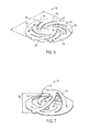
- FIG. 5 is a partial cross-sectional view of an embodiment of the battery of FIG. 3 , illustrating a current collector in an extended position to release gases produced by the battery;
- FIG. 6 is a perspective view of an embodiment of the current collector of FIGS. 4 and 5 with flexible legs and fixed legs to provide a larger opening and improve the electrical conductivity of the current collector;
- FIG. 7 is a perspective view of an embodiment of the current collector of FIG. 6 in an extended position
- FIG. 8 is a perspective view of another embodiment of the current collector of FIGS. 4 and 5 with a differing number of flexible legs and fixed legs;
- FIG. 9 is a perspective view of an embodiment of the current collector of FIG. 8 in an extended position
- FIG. 10 is a perspective view of another embodiment of the current collector of FIGS. 4 and 5 with a single flexible leg;
- FIG. 11 is a perspective view of another embodiment of the current collector of FIGS. 4 and 5 with two flexible legs and two fixed legs;
- FIG. 12 is a perspective view of another embodiment of the current collector of FIGS. 4 and 5 with lunar-shaped flexible legs and fixed legs;
- FIG. 13 Is a perspective view of another embodiment of the current collector of FIGS. 4 and 5 with features to provide a larger opening and improve the electrical conductivity of the current collector.
- the battery includes a current collector that may extend to create an opening within a battery housing, allowing for the release of vent gases.
- the current collector includes at least one flexible leg to provide a larger opening to vent gases more efficiently.
- the current collector may include at least one fixed leg to increase the electrical conductivity of the current collector.
- Typical current collector designs employ legs where a portion of each leg is fixed (e.g., welded to the battery cell), and where a portion is left to flex in response to gas pressure to open the battery housing to allow the gas to vent.
- This subdivision within the legs creates an unfortunate tradeoff between flexibility and electrical conductivity. In other words, providing a greater area on the leg for one purpose (e.g., electrical conductivity) inherently decreases the available area for the other purpose (e.g., creating the opening).
- the present disclosure provides separate legs that are designed for substantially singular purposes (e.g., either electrical conductivity or to create the opening) to increase the opening size and the electrical conductivity of the current collector.
- FIG. 1 is a perspective view of an embodiment of a vehicle 10 in the form of an automobile (e.g., a car) having a battery system 12 for providing power to various components of the vehicle 10 .
- the battery system 12 may provide all or a portion of the motive power for the vehicle 10 .
- a vehicle 10 may be an electric vehicle (EV), a hybrid electric vehicle (HEV), a plug-in hybrid electric vehicle (PHEV), or another type of vehicle using electric power for propulsion.
- EV electric vehicle
- HEV hybrid electric vehicle
- PHEV plug-in hybrid electric vehicle
- the vehicle 10 is illustrated as a car in FIG. 1 , the type of vehicle may differ according to other embodiments, all of which are intended to fall within the scope of the present disclosure.
- the vehicle 10 may be a truck, bus, industrial vehicle, motorcycle, recreational vehicle, boat, or any other type of vehicle that may benefit from the use of electric power for all or a portion of its propulsion power.
- the vehicle 10 may include various internal components, such as a motor, a transmission system, and the like.
- FIG. 2 is a cutaway schematic view of the vehicle 10 .
- the battery system 12 is provided toward the rear of the vehicle 10 proximate a fuel tank 14 . It should be noted that the battery system 12 may be located in various areas within the vehicle 10 , such as immediately adjacent the fuel tank 14 or in a separate compartment of the vehicle 10 .
- the battery system 12 is used to provide power to an electric motor 16 , which, in turn, may provide all or a portion of the motive power for the vehicle 10 .
- An internal combustion engine 18 may also be used to provide a portion of the motive power for the vehicle 10 .
- the electric motor 16 and the engine 18 are coupled to a transmission system 20 to provide motive power for the vehicle.
- the transmission system 20 provides a controlled application of power from the electric motor 16 and the engine 18 to a plurality of wheels 22 .
- the type of the vehicle 10 may differ, and the number of wheels may also differ accordingly.
- the vehicle 10 may have 2 wheels (e.g., a motorcycle), 3 wheels (e.g., an all-terrain vehicle), 4 wheels (e.g., a car), or 5 or more wheels (e.g., a truck, bus, and the like).
- the electric motor 16 is powered by a plurality of electrochemical cells or batteries 24 within the battery system 12 . That is, the batteries 24 supply electrical energy to the electric motor 16 , which converts the electrical energy into mechanical energy to rotate the wheels 22 .
- the batteries 24 include various components to enable the transfer of energy to the electric motor 16 , which is explained in greater detail with respect to FIG. 3 .
- FIG. 3 is an exploded view of an embodiment of the battery 24 used to supply power to the electric motor 16 .
- components of the battery 24 are contained within a generally cylindrical battery housing 26 .
- the shape of the housing 26 may vary according to implementation-specific designs, and may be prismatic, polyhedral, or any other suitable shape.
- the battery 24 includes a cell element 28 , which includes an electrolyte (e.g., lithium, nickel-metal-hydride, lead, and the like).
- the electrolyte stores chemical potential energy that may later be converted into electrical energy for the electric motor 16 of FIG. 2 .
- the cell element 28 includes a positive electrode 30 and a negative electrode 32 .
- the positive electrode 30 is coupled to a positive terminal 34 of the battery 24 via a positive current collector 36 .
- the negative electrode 32 is coupled to a negative terminal 38 of the battery 24 through a negative current collector 40 .
- Insulating spacers 42 and 44 electrically isolate the positive and negative electrodes 30 and 32 from each other.
- an electrical connection is made between the positive and negative terminals 34 and 38 of the battery 24 , an electrical circuit is formed between the positive and negative electrodes 30 and 32 , thereby allowing current to flow from the battery 24 .
- Gases may accumulate within the battery housing 26 as a result of the chemical reactions occurring within the cell element 28 . Build-up of these gases may increase the pressure within the battery housing 26 , thereby reducing the operability of the battery 24 . If the pressure becomes great enough, it may be is desirable to vent the gases to relieve the pressure within the battery housing 26 . To this end, the battery 24 is equipped with a vent disk 46 that may separate from the battery housing 26 to enable trapped gases to escape, as is more readily seen in FIGS. 4 and 5 .
- FIG. 4 is a partial cross-sectional view of the battery housing 26 taken along line 4 - 4 of FIG. 3 .
- the vent disk 46 is coupled to the housing 26 and to the cell element 28 . While the vent disk 46 is connected to the housing 26 , gases formed by the chemical reactions of the cell element 28 may accumulate within the housing 26 , which decreases the operability of the battery 24 .
- the current collector 36 includes features that allow the vent disk 46 to move away from the housing 26 , thereby creating an opening through which the gases may escape the housing 26 .
- FIG. 5 illustrates the current collector 36 having at least one flexible leg 48 that can extend along an axis 50 of the battery 24 . That is, the flexible leg 48 extends to allow the vent disk 46 to move away from the housing 26 in a direction generally along the longitudinal axis 50 of the battery 24 and of the current collector 36 . Pressure or force applied by the accumulated gases within the housing 26 causes the flexible leg 48 to extend, thereby separating the vent disk 46 from the housing 26 and creating an opening 52 in the housing 26 . The accumulated gases are then vented out of the housing through the opening 52 , as shown by arrows 54 .
- the opening 52 breaks the electrical connection between the positive and negative electrodes of the cell element 28 , which reduces or stops current flow from the battery 24 .
- This may be desirable, as a rapid accumulation of gases within the housing 26 can be indicative of an operating issue with the battery 24 , such as an overcharge or an overvoltage.
- the current collector 36 it is desirable for the current collector 36 to be simultaneously electrically conductive and able to move a suitable distance to create a large opening to vent gases quickly.
- a greater electrical conductivity i.e., a lower electrical resistance
- a larger opening 52 results in a higher rate of venting the gases from the housing 26 .
- the presently disclosed embodiments are directed to features of the current collector 36 to provide the larger opening 52 and to improve the electrical conductivity of the current collector 36 .
- FIG. 6 illustrates an embodiment of the current collector 36 with features to improve its operability.
- the current collector 36 includes a substantially flat central portion 56 surrounded by a substantially flat outer portion 58 .
- the term “substantially flat” is not intended to limit the geometry of the current collector 36 .
- the current collector 36 may include protrusions, depressions, variations in thickness, and the like, which fall within the scope and spirit of the present disclosure.
- the substantially flat outer portion defines an outer width 59 .
- the illustrated central portion 56 is generally circular and the outer portion 58 is generally annular, the shapes of the respective portions may differ based on the shape of the battery 24 .
- the shape of the housing 26 may be cylindrical, prismatic, polyhedral, and the like. Accordingly, the shapes of the central portion 56 and the outer portion 58 may be generally circular, polygonal, annular, and the like.
- the current collector 36 may be constructed from aluminum or another conductive material.
- the current collector 36 is generally thin (e.g., approximately 0.8 cm thickness) to allow movement.
- the aforementioned material of construction and thickness are given by way of example, and are not intended to be limiting.
- the central portion 56 may be coupled to the vent disk 46 of FIGS. 4-5 and the outer portion 58 may be coupled to the cell element 28 .
- Extension of the flexible legs 48 causes the vent disk 46 to separate from the battery housing 26 , as noted previously.
- the central portion 56 may instead be coupled to the cell element 28 while the outer portion 58 is coupled to the vent disk 46 .
- the current collector 36 may be coupled to the battery 24 in different areas, extension of the flexible legs 48 in the direction generally orthogonal to the plane of the current collector 36 (i.e., generally parallel to the axis 50 ) still creates the opening 52 , thereby enabling the vent gases to escape.
- the current collector 36 includes fixed legs 60 to improve the electrical conductivity of the current collector 36 .
- the flexible legs 48 and fixed legs 60 are separated by a series of substantially circular grooves 62 . Accordingly, the flexible legs 48 and fixed legs 60 are defined by partial lunar shapes (i.e., the area between the circular grooves 62 ). However, the shape of the grooves 62 , the flexible legs 48 , and the fixed legs 60 may differ, and may be any suitable shape, such as straight, a lune, a crescent, an oval, a polygon, etc.
- the fixed legs 60 extend from the outer portion 58 toward the central portion 56 .
- the fixed legs 60 are not coupled to the central portion 56 .
- the flexible legs 48 extend from the outer portion 58 to the central portion 56 and are coupled to the central portion 56 . This enables the flexible legs 48 to provide relative movement between the central portion 56 and the outer portion 58 of the current collector 58 , thereby creating the opening 52 .
- each of the legs 48 and 60 provide substantially singular functions. That is, the flexible legs 48 provide the larger opening 52 , whereas the fixed legs 60 provide electrical contact between the cell element 28 and various parts of the battery 24 . As a result, the larger opening 52 is provided and the electrical conductivity of the current collector 36 is improved.
- the fixed leg 60 defines an electrical contact length 64 , as measured from the outer portion 58 to the end of the groove 62 .
- the electrical contact length 64 may be provided by, for example, a laser weld that conductively couples the fixed leg to the cell element 28 .
- the fixed leg 60 is designed such that the electrical contact length 64 is at least 30 percent of the outer width 59 of the outer portion 58 .
- the outer width 59 of the current collector 36 may be approximately 50 mm, and the electrical contact length 64 may be approximately 15 mm.
- the electrical contact length 64 may vary.
- the electrical contact length 64 may be between 35 and 75 percent, or 45 and 55 percent of the outer width 59 .
- the improved electrical contact length 64 increases the electrical conductivity of the current collector 36 , thereby improving the operability of the battery 24 .
- FIG. 7 illustrates the current collector 36 in an extended position (such as in FIG. 5 ).
- the fixed legs 60 retain their original positions, whereas the flexible legs 48 extend in a direction generally orthogonal to the plane of the current collector 36 (e.g., orthogonally to the central portion 56 or the outer portion 58 ).
- the flexible legs 48 and the central portion 56 move a distance 66 when a force is applied between the central portion 56 and the outer portion 58 .
- the distance 66 is at least 16 percent of the outer width 59 of the outer portion 58 in response to a 1000 Newton load, as determined by finite-element analysis (FEA).
- FEA finite-element analysis
- the outer width 59 of the current collector 36 may be approximately 35 mm, and the distance 66 may be approximately 12 mm.
- the distance 66 that the flexible legs 48 extend may vary.
- the distance 66 may be between 18 and 40 percent, or 25 and 38 percent of the outer width 59 when a 1000 Newton is applied between the central portion 56 and the outer portion 58 .
- the electrical contact length 64 and the distance 66 may be varied based on the design of the fixed legs 60 and the flexible legs 48 , respectively.
- the current collector 36 illustrated by FIG. 7 includes an equal number of fixed legs 60 and flexible legs 48 (i.e., 4 of each), certain embodiments may include a differing number of fixed legs 60 and/or flexible legs 48 to achieve a desired opening size and/or electrical conductivity for the current collector 36 .
- the current collector includes at least one flexible leg 48 (i.e., 1, 2, 3, 4, or more) and may include 1, 2, 3, 4, or more fixed legs 60 , as is illustrated by the embodiments of FIGS. 8-13 .
- the current collector may not include any fixed legs 60 .
- FIGS. 8-9 illustrate an embodiment of the current collector 36 having eight flexible legs 48 and four fixed legs 60 .
- the additional flexible legs 48 improve the overall mechanical strength of the current collector 36 .
- the flexible legs 48 extend the distance 66 orthogonally to the current collector 36 , and the distance 66 is at least 16 percent of the outer width 59 of the current collector.
- the outer width 59 is approximately 35 mm
- the distance 66 is approximately 6 mm.
- the distance may be between 18 and 40 percent, or 25 and 38 percent of the outer width 59 when a 1000 Newton is applied between the central portion 56 and the outer portion 58 .
- the distance 66 may be modified by changing the number of flexible legs 48 .
- FIG. 10 is a perspective view of another embodiment of the current collector 36 having a single flexible leg 48 in a spiral arrangement.
- the current collector 36 does not include a fixed leg 60 .
- the outer portion 58 may provide the entirety of the electrical contact between the cell element 28 and the housing 26 .
- the illustrated embodiment provides the flexible leg 48 with a greater length relative to the outer width.
- FIG. 11 illustrates an embodiment of the current collector 36 having 10 flexible legs 48 and five fixed legs 60 .
- the fixed legs 60 define the electrical contact length 64 , which is at least 30 percent of the outer width 59 of the outer portion 58 .
- the outer width 59 may be approximately 35 mm
- the electrical contact length 64 may be approximately 16 mm.
- a total electrical contact length may be defined as the sum of the electrical contact lengths 64 of each fixed leg 60 . Increasing the total electrical contact length generally increases the electrical conductivity of the current collector 36 . Thus, the total electrical contact length, and thus the electrical conductivity of the current collector 36 , may be modified by changing the number of fixed legs 60 .
- FIG. 12 is a perspective view of another embodiment of the current collector 36 having two flexible legs 48 and two fixed legs 60 in a generally symmetrical arrangement.
- the symmetrical arrangement of legs may reduce the amount of twisting (e.g., circumferential movement) of the flexible legs 48 as they extend to create the opening 52 . This may be desirable, as it may increase the distance 66 that the flexible legs 48 extend when they are exposed to the 1000 Newton loading.
- certain embodiments have the legs 48 and 60 disposed in an asymmetrical arrangement.
- Such an arrangement may increase the amount of circumferential twisting of the flexible legs 48 about the longitudinal axis 50 as they extend to create the opening 52 , which may enable a smaller amount of force to create the opening 52 .
- the symmetry or asymmetry of the legs may vary among embodiments.
- the shape and symmetry of the legs may be based on various factors, such as the geometry, size, or application of the battery.
- FIG. 13 illustrates another embodiment of the current collector 36 having the flexible legs 48 with arcuate sides 68 .
- the arcuate sides 68 are defined by the grooves 62 , which, in the illustrated embodiment, have crescent shapes. In other words, the sides 68 are generally circular, but may have varying radii.
- the shape of the legs 48 and 60 , as well as the corresponding grooves 62 are a design choice and may vary among embodiments.
- the legs 48 and 60 may be arcuate, lunar, straight, or otherwise polygonal
- the grooves 62 may be arcuate, lunar, crescent, polygonal, and the like.
Abstract
Description
Claims (16)
Priority Applications (4)
| Application Number | Priority Date | Filing Date | Title |
|---|---|---|---|
| US13/571,144 US9496539B2 (en) | 2011-08-12 | 2012-08-09 | Current collector for an electromechanical cell |
| EP12780343.5A EP2742550B1 (en) | 2011-08-12 | 2012-10-02 | Current collector for an electromechanical cell |
| CN201280044131.9A CN103797611B (en) | 2011-08-12 | 2012-10-02 | Collector for electrochemical cell |
| PCT/US2012/058482 WO2013026069A1 (en) | 2011-08-12 | 2012-10-02 | Current collector for an electromechanical cell |
Applications Claiming Priority (2)
| Application Number | Priority Date | Filing Date | Title |
|---|---|---|---|
| US201161523075P | 2011-08-12 | 2011-08-12 | |
| US13/571,144 US9496539B2 (en) | 2011-08-12 | 2012-08-09 | Current collector for an electromechanical cell |
Publications (2)
| Publication Number | Publication Date |
|---|---|
| US20130040176A1 US20130040176A1 (en) | 2013-02-14 |
| US9496539B2 true US9496539B2 (en) | 2016-11-15 |
Family
ID=47677727
Family Applications (1)
| Application Number | Title | Priority Date | Filing Date |
|---|---|---|---|
| US13/571,144 Active 2034-12-20 US9496539B2 (en) | 2011-08-12 | 2012-08-09 | Current collector for an electromechanical cell |
Country Status (4)
| Country | Link |
|---|---|
| US (1) | US9496539B2 (en) |
| EP (1) | EP2742550B1 (en) |
| CN (1) | CN103797611B (en) |
| WO (1) | WO2013026069A1 (en) |
Families Citing this family (5)
| Publication number | Priority date | Publication date | Assignee | Title |
|---|---|---|---|---|
| WO2010059957A2 (en) | 2008-11-21 | 2010-05-27 | Johnson Controls - Saft Advanced Power Solutions Llc | Current collector for an electrochemical cell |
| US20180019476A1 (en) * | 2015-01-30 | 2018-01-18 | The Regents Of The University Of California | Modified charge collectors and cell cases for enhanced battery-cell robustness |
| WO2018026728A1 (en) * | 2016-08-01 | 2018-02-08 | Johnson Controls Technology Company | Overcharge protection assembly for a battery cell |
| WO2018026850A1 (en) | 2016-08-01 | 2018-02-08 | Johnson Controls Technology Company | Overcharge protection systems having dual spiral disk features for prismatic lithium ion battery cells |
| KR102524932B1 (en) * | 2019-02-01 | 2023-04-25 | 주식회사 엘지에너지솔루션 | Secondary battery |
Citations (11)
| Publication number | Priority date | Publication date | Assignee | Title |
|---|---|---|---|---|
| EP0785585A1 (en) | 1996-01-22 | 1997-07-23 | Rayovac Corporation | Electrochemical cells and current collectors therefor |
| US5853912A (en) | 1996-07-10 | 1998-12-29 | Saft America, Inc. | Lithium ion electrochemical cell with safety valve electrical disconnect |
| EP0959508A1 (en) | 1998-05-22 | 1999-11-24 | Texas Instruments Incorporated | Current interrupt apparatus particularly adapted for use with prismatic electrochemical cells |
| US20060210880A1 (en) | 1993-11-19 | 2006-09-21 | Medtronic, Inc. | Current collector |
| US20060228620A1 (en) | 2004-04-28 | 2006-10-12 | Eveready Battery Company, Inc. | Closure vent seal and assembly |
| US20070009785A1 (en) | 2005-07-11 | 2007-01-11 | Kiyomi Kozuki | Sealed rechargeable battery |
| US20080070098A1 (en) | 2006-07-31 | 2008-03-20 | Ray Robert E Jr | Electrochemical cell and current collector assembly therefor |
| US20080131769A1 (en) | 2003-04-04 | 2008-06-05 | Yuuichi Sato | Nonaqueous electrolyte secondary battery |
| US20090274949A1 (en) | 2008-05-02 | 2009-11-05 | Sony Corporation | Nonaqueous electrolyte battery |
| WO2010059957A2 (en) | 2008-11-21 | 2010-05-27 | Johnson Controls - Saft Advanced Power Solutions Llc | Current collector for an electrochemical cell |
| EP2270899A1 (en) | 2009-06-15 | 2011-01-05 | Saft Groupe S.A. | Container for sealed accumulator |
-
2012
- 2012-08-09 US US13/571,144 patent/US9496539B2/en active Active
- 2012-10-02 CN CN201280044131.9A patent/CN103797611B/en active Active
- 2012-10-02 WO PCT/US2012/058482 patent/WO2013026069A1/en active Application Filing
- 2012-10-02 EP EP12780343.5A patent/EP2742550B1/en active Active
Patent Citations (12)
| Publication number | Priority date | Publication date | Assignee | Title |
|---|---|---|---|---|
| US20060210880A1 (en) | 1993-11-19 | 2006-09-21 | Medtronic, Inc. | Current collector |
| EP0785585A1 (en) | 1996-01-22 | 1997-07-23 | Rayovac Corporation | Electrochemical cells and current collectors therefor |
| US5853912A (en) | 1996-07-10 | 1998-12-29 | Saft America, Inc. | Lithium ion electrochemical cell with safety valve electrical disconnect |
| EP0959508A1 (en) | 1998-05-22 | 1999-11-24 | Texas Instruments Incorporated | Current interrupt apparatus particularly adapted for use with prismatic electrochemical cells |
| US20080131769A1 (en) | 2003-04-04 | 2008-06-05 | Yuuichi Sato | Nonaqueous electrolyte secondary battery |
| US20060228620A1 (en) | 2004-04-28 | 2006-10-12 | Eveready Battery Company, Inc. | Closure vent seal and assembly |
| US20070009785A1 (en) | 2005-07-11 | 2007-01-11 | Kiyomi Kozuki | Sealed rechargeable battery |
| US20080070098A1 (en) | 2006-07-31 | 2008-03-20 | Ray Robert E Jr | Electrochemical cell and current collector assembly therefor |
| US20090274949A1 (en) | 2008-05-02 | 2009-11-05 | Sony Corporation | Nonaqueous electrolyte battery |
| WO2010059957A2 (en) | 2008-11-21 | 2010-05-27 | Johnson Controls - Saft Advanced Power Solutions Llc | Current collector for an electrochemical cell |
| US20110256433A1 (en) | 2008-11-21 | 2011-10-20 | Johnson Controls- Saft Advanced Power Solutions Llc | Current collector for an electrochemical cell |
| EP2270899A1 (en) | 2009-06-15 | 2011-01-05 | Saft Groupe S.A. | Container for sealed accumulator |
Non-Patent Citations (2)
| Title |
|---|
| International Search Report and Written Opinion for PCT No. PCT/US2012/058482 dated Jan. 7, 2013; 16 pages. |
| U.S. Appl. No. 13/571,183, filed Aug. 9, 2012, Fuhr et al. |
Also Published As
| Publication number | Publication date |
|---|---|
| CN103797611A (en) | 2014-05-14 |
| WO2013026069A1 (en) | 2013-02-21 |
| US20130040176A1 (en) | 2013-02-14 |
| CN103797611B (en) | 2016-11-23 |
| EP2742550B1 (en) | 2016-03-02 |
| EP2742550A1 (en) | 2014-06-18 |
Similar Documents
| Publication | Publication Date | Title |
|---|---|---|
| US11165125B2 (en) | Prismatic secondary battery and assembled battery using the same | |
| US8679678B2 (en) | Current collector for an electromechanical cell | |
| US8609278B2 (en) | Battery cell | |
| US9496539B2 (en) | Current collector for an electromechanical cell | |
| US20120196180A1 (en) | Electrode for electric storage device and electric storage device | |
| US8906532B2 (en) | Electrochemical cells with improved heat collection and transfer systems | |
| EP3446346B1 (en) | Multicavity battery module | |
| US20130130099A1 (en) | Secondary battery of differential lead structure | |
| US10290841B2 (en) | Cover for battery cell | |
| EP3201975B1 (en) | Battery module bus bar connection assembly | |
| JP2009272169A (en) | Power storage device | |
| US20110129712A1 (en) | Mandrel with drive member for electrochemical cells | |
| US20210202924A1 (en) | Lithium-ion battery device for vehicle | |
| CN111092251A (en) | Pouch type battery cell | |
| KR20180081921A (en) | Housing structure of Battery module | |
| KR101890014B1 (en) | Electrode lead and battery module for high capacity comprising the same | |
| JP7054441B2 (en) | Batteries assembled | |
| JP2020119718A (en) | battery |
Legal Events
| Date | Code | Title | Description |
|---|---|---|---|
| AS | Assignment |
Owner name: JOHNSON CONTROLS TECHNOLOGY LLC, DELAWARE Free format text: ASSIGNMENT OF ASSIGNORS INTEREST;ASSIGNORS:TYLER, MATTHEW R.;FUHR, JASON D.;REEL/FRAME:028760/0808 Effective date: 20120808 |
|
| STCF | Information on status: patent grant |
Free format text: PATENTED CASE |
|
| AS | Assignment |
Owner name: CPS TECHNOLOGY HOLDINGS LLC, NEW YORK Free format text: ASSIGNMENT OF ASSIGNORS INTEREST;ASSIGNOR:JOHNSON CONTROLS TECHNOLOGY LLC;REEL/FRAME:049657/0573 Effective date: 20190430 |
|
| AS | Assignment |
Owner name: CITIBANK N.A., AS COLLATERAL AGENT, NEW YORK Free format text: ABL PATENT SECURITY AGREEMENT;ASSIGNOR:CPS TECHNOLOGY HOLDINGS LLC;REEL/FRAME:050229/0079 Effective date: 20190827 Owner name: CITIBANK N.A., AS COLLATERAL AGENT, DELAWARE Free format text: FIRST LIEN PATENT SECURITY AGREEMENT;ASSIGNOR:CPS TECHNOLOGY HOLDINGS LLC;REEL/FRAME:050229/0029 Effective date: 20190827 |
|
| MAFP | Maintenance fee payment |
Free format text: PAYMENT OF MAINTENANCE FEE, 4TH YEAR, LARGE ENTITY (ORIGINAL EVENT CODE: M1551); ENTITY STATUS OF PATENT OWNER: LARGE ENTITY Year of fee payment: 4 |