EP2270899A1 - Container for sealed accumulator - Google Patents
Container for sealed accumulator Download PDFInfo
- Publication number
- EP2270899A1 EP2270899A1 EP10164390A EP10164390A EP2270899A1 EP 2270899 A1 EP2270899 A1 EP 2270899A1 EP 10164390 A EP10164390 A EP 10164390A EP 10164390 A EP10164390 A EP 10164390A EP 2270899 A1 EP2270899 A1 EP 2270899A1
- Authority
- EP
- European Patent Office
- Prior art keywords
- container
- lid
- connecting piece
- container according
- rupture
- Prior art date
- Legal status (The legal status is an assumption and is not a legal conclusion. Google has not performed a legal analysis and makes no representation as to the accuracy of the status listed.)
- Granted
Links
- 230000002093 peripheral effect Effects 0.000 claims abstract description 32
- 230000009975 flexible effect Effects 0.000 claims abstract description 23
- 239000004020 conductor Substances 0.000 claims abstract description 6
- 229910052782 aluminium Inorganic materials 0.000 claims description 7
- XAGFODPZIPBFFR-UHFFFAOYSA-N aluminium Chemical compound [Al] XAGFODPZIPBFFR-UHFFFAOYSA-N 0.000 claims description 7
- 238000006073 displacement reaction Methods 0.000 claims description 6
- 230000035939 shock Effects 0.000 description 8
- 239000000463 material Substances 0.000 description 7
- 239000007789 gas Substances 0.000 description 6
- 238000005452 bending Methods 0.000 description 3
- 230000000284 resting effect Effects 0.000 description 3
- PXHVJJICTQNCMI-UHFFFAOYSA-N Nickel Chemical compound [Ni] PXHVJJICTQNCMI-UHFFFAOYSA-N 0.000 description 2
- 238000009825 accumulation Methods 0.000 description 2
- 150000001875 compounds Chemical class 0.000 description 2
- 239000003792 electrolyte Substances 0.000 description 2
- 238000009432 framing Methods 0.000 description 2
- 239000000615 nonconductor Substances 0.000 description 2
- 230000001960 triggered effect Effects 0.000 description 2
- RYGMFSIKBFXOCR-UHFFFAOYSA-N Copper Chemical compound [Cu] RYGMFSIKBFXOCR-UHFFFAOYSA-N 0.000 description 1
- WHXSMMKQMYFTQS-UHFFFAOYSA-N Lithium Chemical compound [Li] WHXSMMKQMYFTQS-UHFFFAOYSA-N 0.000 description 1
- HBBGRARXTFLTSG-UHFFFAOYSA-N Lithium ion Chemical compound [Li+] HBBGRARXTFLTSG-UHFFFAOYSA-N 0.000 description 1
- 239000004411 aluminium Substances 0.000 description 1
- 230000009172 bursting Effects 0.000 description 1
- 229910052802 copper Inorganic materials 0.000 description 1
- 239000010949 copper Substances 0.000 description 1
- 230000007123 defense Effects 0.000 description 1
- 230000000694 effects Effects 0.000 description 1
- 238000003487 electrochemical reaction Methods 0.000 description 1
- 239000011262 electrochemically active material Substances 0.000 description 1
- 238000004880 explosion Methods 0.000 description 1
- 238000002955 isolation Methods 0.000 description 1
- 229910052744 lithium Inorganic materials 0.000 description 1
- 229910001416 lithium ion Inorganic materials 0.000 description 1
- 229910052751 metal Inorganic materials 0.000 description 1
- 239000002184 metal Substances 0.000 description 1
- 229910052759 nickel Inorganic materials 0.000 description 1
- 239000007787 solid Substances 0.000 description 1
- 229910001220 stainless steel Inorganic materials 0.000 description 1
- 239000010935 stainless steel Substances 0.000 description 1
- 230000003313 weakening effect Effects 0.000 description 1
Images


Classifications
-
- H—ELECTRICITY
- H01—ELECTRIC ELEMENTS
- H01M—PROCESSES OR MEANS, e.g. BATTERIES, FOR THE DIRECT CONVERSION OF CHEMICAL ENERGY INTO ELECTRICAL ENERGY
- H01M50/00—Constructional details or processes of manufacture of the non-active parts of electrochemical cells other than fuel cells, e.g. hybrid cells
- H01M50/30—Arrangements for facilitating escape of gases
- H01M50/342—Non-re-sealable arrangements
- H01M50/3425—Non-re-sealable arrangements in the form of rupturable membranes or weakened parts, e.g. pierced with the aid of a sharp member
-
- H—ELECTRICITY
- H01—ELECTRIC ELEMENTS
- H01M—PROCESSES OR MEANS, e.g. BATTERIES, FOR THE DIRECT CONVERSION OF CHEMICAL ENERGY INTO ELECTRICAL ENERGY
- H01M50/00—Constructional details or processes of manufacture of the non-active parts of electrochemical cells other than fuel cells, e.g. hybrid cells
- H01M50/50—Current conducting connections for cells or batteries
- H01M50/531—Electrode connections inside a battery casing
-
- H—ELECTRICITY
- H01—ELECTRIC ELEMENTS
- H01M—PROCESSES OR MEANS, e.g. BATTERIES, FOR THE DIRECT CONVERSION OF CHEMICAL ENERGY INTO ELECTRICAL ENERGY
- H01M50/00—Constructional details or processes of manufacture of the non-active parts of electrochemical cells other than fuel cells, e.g. hybrid cells
- H01M50/50—Current conducting connections for cells or batteries
- H01M50/572—Means for preventing undesired use or discharge
- H01M50/574—Devices or arrangements for the interruption of current
- H01M50/578—Devices or arrangements for the interruption of current in response to pressure
-
- Y—GENERAL TAGGING OF NEW TECHNOLOGICAL DEVELOPMENTS; GENERAL TAGGING OF CROSS-SECTIONAL TECHNOLOGIES SPANNING OVER SEVERAL SECTIONS OF THE IPC; TECHNICAL SUBJECTS COVERED BY FORMER USPC CROSS-REFERENCE ART COLLECTIONS [XRACs] AND DIGESTS
- Y02—TECHNOLOGIES OR APPLICATIONS FOR MITIGATION OR ADAPTATION AGAINST CLIMATE CHANGE
- Y02E—REDUCTION OF GREENHOUSE GAS [GHG] EMISSIONS, RELATED TO ENERGY GENERATION, TRANSMISSION OR DISTRIBUTION
- Y02E60/00—Enabling technologies; Technologies with a potential or indirect contribution to GHG emissions mitigation
- Y02E60/10—Energy storage using batteries
Definitions
- the present invention relates to the container field for sealed accumulators.
- a sealed electrochemical accumulator or sealed current generator (these two terms being equivalent, the term accumulator will be used in the present description) comprises, in a manner known per se, a container, containing an electrochemical bundle comprising an alternation of positive and negative electrodes. framing separators impregnated with electrolyte.
- Each electrode is composed of a metal current collector supporting on at least one of its faces the electrochemically active material.
- the electrode is electrically connected to a current output which provides electrical continuity between the electrode and the external application to which the accumulator is associated.
- the electrode beam is disposed in a sealed container by a lid.
- the invention relates to sealed accumulators for example of the type, primary lithium and lithium-ion.
- These accumulators may be cylindrical or rectangular format (also known as prismatic).
- An accumulator is generally designed to operate under so-called nominal conditions, i.e. within given temperature, current and voltage ranges.
- nominal conditions i.e. within given temperature, current and voltage ranges.
- the accumulation of these gases in the container causes an increase in the internal pressure of the accumulator, which can lead to a violent bursting of the container and the projection of harmful chemical compounds and corrosive to the environment and people in the vicinity .
- Safety devices exist which prevent the accumulation of gases inside the container of a sealed accumulator and allow their evacuation when the internal pressure exceeds a predetermined value.
- a battery safety device also has the function of circuit breaker, capable of electrically and irreversibly isolating the devices connected to the battery.
- This accumulator comprises an alternation of positive and negative electrodes respectively connected to current output terminals.
- the electrodes are arranged in a container having a cylindrical wall closed by a bottom.
- the bottom is formed in three parts, a peripheral portion connected to the cylindrical wall, a lid and a thinning connecting the lid to the peripheral portion. Thinning is adapted to be torn by an overpressure inside the container.
- a planar connection connects the positive electrode of the bundle to the bottom wall of the container, the container walls being electrically conductive with the lid.
- a ring-shaped seal is placed between the electrochemical bundle and the bottom of the container.
- a tearing of the thinning is adapted to interrupt the electrical conduction between the electrodes of a polarity and its current output terminal by disconnecting the lid of the peripheral portion.
- the beam is supported on the connection piece. During an overpressure, the thinned portion tears and the beam resting on the lid through the connection moves towards the bottom of the container tearing the entire thinned portion to ensure the power cut between the positive electrode of the electrochemical bundle and the lid of the container.
- Such a container has the disadvantage of being vulnerable to shocks. Indeed, the beam which is the heaviest part of the element is placed on the lid. Following shocks, the weight of the beam exerts a force that can tear the thinning and thus disconnect the lid of the peripheral portion unexpectedly. It has been found that the cover initially designed to open for an internal pressure of the accumulator greater than or equal to 8 bar at 12 bar (depending on the capacity of the accumulator) actually opens for pressure. internal lower (between 0 and 6 bar) when it does not occur during shocks. This is explained by the weakening of the thinning caused by the shocks. Since an accumulator may have an internal pressure of 6 bar at the end of its life, the lid may open unexpectedly.
- This container comprises a side wall and a wall forming a bottom of conductive material.
- the wall forming a bottom comprises a peripheral portion electrically connected to the side wall, a lid and a weakened portion around the lid joining the lid to the peripheral portion.
- the weakened portion is designed to break in order to allow the gas to escape under pressure in the container.
- the container contains an electrically insulating ring mounted on the peripheral portion. This ring is intended to support an electrochemical beam. It serves as an electrical insulator to prevent electrical contact between the edge of a beam electrode and the container wall connected to a reverse polarity electrode, which could cause an internal short circuit after the safety device has been activated.
- the container comprises an electrically conductive flexible connection piece, in contact electric with operculum.
- flexible piece is meant a piece deforming when the positive pressure pushes the cover to the outside, the part being fixed to the cover. During the overpressure resulting in the rupture of said weakened portion, the connecting piece guides the cap to a position after rupture substantially parallel to the position before rupture.
- the electrochemical bundle bears on the insulating ring and the connection piece electrically connecting the bundle to the lid is flexible.
- the electrochemical beam is not supported on the lid, but only on the peripheral portion through the insulating ring. Consequently, following shocks, the weight of the beam does not exert any force on the cover and therefore does not cause a break in the weakened part.
- the overpressure creates a pushing force on the lid directed towards the outside of the container.
- the thrust force causes the fracture of the weakened part. Thanks to the guiding of the lid to a position parallel to its position before rupture, the rupture of the weakened part around the lid is completely effected. As a result, the lid is definitely disconnected from the peripheral portion.
- the container thus makes it possible to electrically disconnect an electrode from its associated terminal while resisting the shocks of the electrochemical bundle in the container.
- the Figures 3A and 3B represent a flexible connection piece according to a first embodiment.
- the flexibility of the connecting piece is ensured both by the type of material chosen (low strength material such as aluminum 1050 for example) and by the geometry of the part which allows unfolding of the connecting piece as that will be described in more detail in the following description.
- connection piece On the figure 3A , the connection piece is shown from above and on the figure 3B , the connection piece is shown in elevation.
- the connecting piece is formed by a connecting portion (3a) intended to be electrically connected to the bundle, a central portion (3b) intended to be fixed to the lid and identical flexible strips (3c) connecting the central portion to the connecting part.
- the slats are spiral, that is to say they have a curved shape, like a spiral, which progressively moves away from the central portion (3b).
- the slats are evenly distributed around the central portion (3b).
- the slats can be spiraled by turning to the right or to the left. On the Figures 3A and 3B the slats turn to the right.
- the slats (3a) are 4 in number substantially forming the cross shaped swastika.
- the number of fins may be greater than 4 or the number of 3.
- the fact of having fins (3a) of this shape makes it possible to make the central portion (3b) movable with respect to the connection portion (3a) in moving the central portion (3b) in a helical motion whose axis passes through the center of the central portion (3b).
- This movement of the central part (3b) is due to the fact that the fins (3c) are spiral and that they flex.
- the fins deform by flexing, unfolding (ie become less and less curved).
- the bending force can be reduced by reducing the thickness of the fin.
- the connecting piece may comprise a plurality of fins which can be superimposed having a smaller thickness so that the bending force is reduced while keeping the same resistivity of the connection piece.
- the container is of substantially cylindrical format and only the end forming the bottom of the container has been shown.
- the bottom of the container comprises a peripheral portion (2a), a cover (2b) and a weakened portion (2c) around the cover (2b), joining the peripheral portion (2a) to the cover (2b).
- the weakened part (2c) on the Figure 2A is a thinned part.
- Thinned zone means a zone of the wall of the container whose thickness is less than the thickness of the central portion (3b) and the lid.
- the peripheral portion (2a) is electrically connected to the side wall (1).
- the side wall (1) and the bottom portions are electrically conductive material.
- the container also comprises an electrically insulating ring (4), mounted on the peripheral portion (2a).
- the ring (4) insulating can for example be a seal.
- the container contains an electrochemical bundle (5) mounted on the insulating ring (4).
- the beam comprising an alternation of positive and negative electrodes framing separators impregnated with electrolyte, and wherein the positive or negative electrodes are electrically connected to a flexible connection piece (3) of electrically conductive material.
- the connecting piece can be for example aluminum, because it is a material having a low resistivity and having little mechanical strength.
- the connection piece may be made of aluminum 1050. In the remainder of the description, it is the positive electrodes that are electrically connected to the connection piece (3).
- the connecting piece (3) is part of the container.
- the connecting piece (3) has at its periphery a ring-shaped connecting portion (3a) having a flat surface. This part can also have a solid disc shape.
- the connecting piece (3) has a central portion (3b) having a flat surface parallel to the surface of the connecting portion (3a). This central portion (3b) is located in a plane parallel to the flat surface of the connection portion (3a).
- the connecting portion (3a) and the central portion (3b) are circular and have the same axis. However, these parts may have other shapes, such as square, rectangular, etc.
- the connecting piece (3) also comprises identical flexible strips (3c) connecting the central part (3b) to the connection part (3a). .
- the slats (3c) are regularly distributed around the central portion (3b).
- Each strip (3c) is spiral with respect to the central portion (3b).
- the four slats with the central part form essentially a Basque cross or a cross of swastika whose branches are the slats.
- the connecting piece has a central symmetry which is the center of the central portion and the connecting portion.
- the central part (3b) is fixed with the cover (2b) and the positive electrodes of the beam (5) are electrically connected to this connection piece (3) via the connecting part (3a).
- the connecting part (3a) is mounted on a shoulder of the isolation ring (4), so that the ring electrically isolates the connection portion (3a) of the peripheral portion (2a) after tearing of the portion weakened (2c).
- the ring (4) is therefore mounted between the connecting piece (3) and the peripheral portion (2a).
- the connecting piece (3) is not necessarily mounted on the ring (4), for example it can be fixed directly to the beam (5).
- the electrical connection between the positive electrodes and the cover (2b) is achieved through the connection piece (3).
- the fins (3c) make it possible to make the connecting piece (3) flexible. Indeed, the fins (3c) make it possible to make the central part (3b) of the connecting part (3a) mobile by bending.
- the displacement of the central portion (3b) relative to the connection portion is a helical movement whose axis passes through its center.
- the rotation of the central part on itself is very small compared to the rectilinear translation for example of 0.09 ° / 1mm or for a final stroke 0.54 ° / 6.3 mm.
- the helical movement of the central portion (3b) is due to the fact that the fins (3c) flex naturally before stretching.
- the planar surface of the central portion (3b) is always parallel to the flat surface of the connection portion (3a) as illustrated in FIGS. Figures 6A and 6B .
- the connecting piece (3) may be a one-piece piece made by cutting followed by a stamping step. The stamping makes it possible to stretch the fins (3c) so that the central portion (3b) is offset in a plane parallel to the connection portion (3b) for mounting the connection piece in the container.
- the connecting piece (3) is very flexible and therefore does not push the lid.
- the connection piece can be slightly compressed between the beam and the cover so that it applies a force of 40 to 100 Newton on the cover.
- the weakened part can be formed so that a rupture of this part is triggered as soon as a pressure which is exerted on it is equal to the compressive force of the connection piece on the operculum. , plus the pressure of the overpressure for which the lid must open to avoid a risk of violent rupture of the container and the projection of harmful chemical compounds and corrosive to the environment and people in the vicinity of the container.
- This pressure of overpressure can be greater than or equal to 5 bars.
- the connecting piece is fixed on the one hand to the cover and on the other hand to the beam (5) or the ring (4) and is mounted in tension in the container.
- the weakened portion may be formed so that a rupture of this part is triggered as soon as a pressure exerted on it is equal to the tensile force of the connecting piece on the operculum, minus the pressure of the overpressure.
- the figure 4 represents a second embodiment of the connection piece (3) seen from above.
- a top view is a view of which the portion of the connecting piece in the foreground is the connecting portion (3a).
- This second embodiment is based on that of the first embodiment described in connection with the Figures 3A and 3B . Therefore the description made for the first embodiment is applicable also to this second embodiment except for the differences which are explained below.
- the flexibility of the connecting piece is also ensured both by the type of material chosen and by the geometry of the part which allows unfolding of the connecting piece when the lid is pushed back by the gases causing an overpressure to inside the container.
- the connecting piece (3) has only 3 fins.
- the fins have the same shape as the branches of the cross in the form of svastiska except that the wings are turned to the left while the branches of the cross shaped swastika to the right.
- the three spiral fins thus move the central portion (3b) in a helical movement to the left.
- the connecting piece (3) has a shape that substantially forms a cross shaped swastika three branches turned to the left.
- the figure 5 represents a third embodiment of the connecting piece (3) seen from above.
- This third embodiment is based on that of the first embodiment described in connection with the Figures 3A and 3B . Therefore the description made for the first embodiment is applicable also to this third embodiment except for the differences which are explained below.
- the flexibility of the connecting piece is also ensured both by the type of material chosen and by the geometry of the part which allows unfolding of the connection piece when the cover is moved after tearing of the weakened part by the gases causing an overpressure inside the container.
- the connecting portion (3a) and the central portion (3b) have a square shape.
- the fins have the same shape as the branches of the cross in the form of svastiska except that the fins are turned to the left while the branches of the cross shaped swastika to the right.
- the four spiral fins thus move the central portion (3b) in a helical movement to the left.
- the fins (3c) and the central portion (3b) substantially form a cross shaped swastika.
- the connecting portion (3a) forms a frame flanking the cross in the shape of a swastika.
- the accumulator comprises the container described above, an electrochemical bundle (5) in the container mounted on the insulating ring (4), the bundle (5) comprising an alternation of negative and positive electrodes surrounding electrolyte-impregnated separators and wherein the positive electrodes are electrically connected to the connection piece (3).
- the container further comprises a lid provided with two current output terminals. One of the terminals is a negative current output terminal connected to at least one negative electrode in the container, and the other terminal is a positive current output terminal connected to at least one positive electrode in the container through the side wall (1), the wall forming the bottom (2) and the connection piece (3).
- connection of the electrodes can of course be reversed, that is to say that the negative electrodes can be connected to one of the terminals of the cover through the connecting piece (3) and the walls of the container and the positive electrodes at the other terminal of the cover.
- the connecting piece must be in a material other than aluminum such as copper, nickel or stainless steel.
- these materials do not have the same mechanical characteristics including that of flexibility.
- the helical movement is also imposed on the cover because they are fixed to one another.
- the connecting piece thus guides the movement of the lid.
- the helicoidal displacement of the lid (2b) has the effect of tearing the entire weakened portion around the lid (2b). Guiding the displacement of the cap (2b) allows it to be completely detached from the peripheral portion (2a) and thus to break the electrical connection therebetween. Without guiding the displacement of the lid (2b), the weakened portion (2c) may not tear completely. Indeed, the lid (2b) can pivot around the untwisted portion, and thus remain in electrical contact with the peripheral portion (2a). Following the helical movement, the seal (2b) is therefore in a position substantially parallel to its position before rupture. This position ensures that the cover (2b) is no longer in contact with the peripheral portion (2a). As a result, the container provides greater resistance to beam shocks (5) while providing electrical disconnection between the electrodes of one polarity and the associated current output terminal.
- the connecting piece (3) is mounted upside down in the container.
- mounting in reverse it is meant that it is the connecting part (3a) which is connected to the cover (2b) and that it is the central part (3b) which is electrically connected to the beam (5).
- the diameter of the lid must therefore have at least the diameter of the connection portion (3a).
- the central portion (3b) can be connected to the beam through an intermediate piece.
- the accumulator according to the invention has applications in the field of aviation, space, defense, stationary and automobile.
Abstract
Description
La présente invention se rapporte au domaine de conteneur pour accumulateurs étanches.The present invention relates to the container field for sealed accumulators.
Un accumulateur électrochimique étanche ou générateur de courant étanche (ces deux termes étant équivalents, on utilisera le terme d'accumulateur dans la présente description) comprend de façon connue en soi un conteneur, contenant un faisceau électrochimique comportant une alternance d'électrodes positives et négatives encadrant des séparateurs imprégnés d'électrolyte. Chaque électrode est composée d'un collecteur de courant métallique supportant sur au moins une de ses faces la matière électrochimiquement active. L'électrode est connectée électriquement à une sortie de courant qui assure la continuité électrique entre l'électrode et l'application extérieure à laquelle l'accumulateur est associé. Le faisceau d'électrodes est disposé dans un conteneur fermé de manière étanche par un couvercle.A sealed electrochemical accumulator or sealed current generator (these two terms being equivalent, the term accumulator will be used in the present description) comprises, in a manner known per se, a container, containing an electrochemical bundle comprising an alternation of positive and negative electrodes. framing separators impregnated with electrolyte. Each electrode is composed of a metal current collector supporting on at least one of its faces the electrochemically active material. The electrode is electrically connected to a current output which provides electrical continuity between the electrode and the external application to which the accumulator is associated. The electrode beam is disposed in a sealed container by a lid.
L'invention concerne les accumulateurs étanches par exemple de type, lithium primaire et lithium-ion. Ces accumulateurs peuvent être de format cylindrique ou de format rectangulaire (connu également sous le terme de prismatique).The invention relates to sealed accumulators for example of the type, primary lithium and lithium-ion. These accumulators may be cylindrical or rectangular format (also known as prismatic).
Un accumulateur est généralement conçu pour fonctionner dans des conditions dites nominales, c'est-à-dire dans des gammes de température, courant et tension données. L'utilisation d'un accumulateur étanche hors des conditions nominales, comme par exemple une surcharge accidentelle, un court-circuit, une température supérieure à la température maximale de fonctionnement, etc., crée un risque d'explosion. En effet, de telles situations entraînent des réactions de l'électrochimie et génèrent des gaz. L'accumulation de ces gaz dans le conteneur entraîne une augmentation de la pression interne de l'accumulateur, qui peut conduire à un éclatement violent du conteneur et à la projection de composés chimiques nocifs et corrosifs pour l'environnement et les personnes situées à proximité.An accumulator is generally designed to operate under so-called nominal conditions, i.e. within given temperature, current and voltage ranges. The use of a sealed accumulator outside the nominal conditions, such as accidental overload, short circuit, temperature above the maximum operating temperature, etc., creates a risk of explosion. Indeed, such situations lead to electrochemical reactions and generate gases. The accumulation of these gases in the container causes an increase in the internal pressure of the accumulator, which can lead to a violent bursting of the container and the projection of harmful chemical compounds and corrosive to the environment and people in the vicinity .
Des dispositifs de sécurité existent, qui évitent l'accumulation des gaz à l'intérieur du conteneur d'un accumulateur étanche et permettent leur évacuation lorsque la pression interne excède une valeur prédéterminée.Safety devices exist which prevent the accumulation of gases inside the container of a sealed accumulator and allow their evacuation when the internal pressure exceeds a predetermined value.
Par ailleurs, il est nécessaire qu'un dispositif de sécurité pour accumulateur possède également la fonction de coupe-circuit, apte à isoler électriquement et de façon irréversible, les appareils connectés à l'accumulateur.Furthermore, it is necessary that a battery safety device also has the function of circuit breaker, capable of electrically and irreversibly isolating the devices connected to the battery.
Il est connu du document
Un tel conteneur présente cependant l'inconvénient d'être vulnérable aux chocs. En effet, le faisceau qui est la partie la plus lourde de l'élément est posé sur l'opercule. Suite à des chocs, le poids du faisceau exerce une force qui peut déchirer l'amincissement et donc déconnecter l'opercule de la partie périphérique de manière imprévue. On a constaté que l'opercule conçu initialement pour s'ouvrir pour une pression interne de l'accumulateur supérieure ou égale à 8 bars à 12 bars (en fonction de la capacité de l'accumulateur), s'ouvre en réalité pour une pression interne plus basse (entre 0 et 6 bars) quand elle ne se produit pas lors des chocs. Ceci s'explique par la fragilisation de l'amincissement provoquée par les chocs. Etant donné qu'un accumulateur peut avoir une pression interne de 6 bars en fin de vie, l'opercule peut s'ouvrir de façon inopinée.Such a container, however, has the disadvantage of being vulnerable to shocks. Indeed, the beam which is the heaviest part of the element is placed on the lid. Following shocks, the weight of the beam exerts a force that can tear the thinning and thus disconnect the lid of the peripheral portion unexpectedly. It has been found that the cover initially designed to open for an internal pressure of the accumulator greater than or equal to 8 bar at 12 bar (depending on the capacity of the accumulator) actually opens for pressure. internal lower (between 0 and 6 bar) when it does not occur during shocks. This is explained by the weakening of the thinning caused by the shocks. Since an accumulator may have an internal pressure of 6 bar at the end of its life, the lid may open unexpectedly.
Il existe donc un besoin pour un conteneur comprenant un opercule permettant d'interrompre la connexion électrique lors d'une surpression qui est moins vulnérable aux chocs.There is therefore a need for a container comprising a cap for interrupting the electrical connection during an overpressure which is less vulnerable to shocks.
A cette fin, la présente invention propose un conteneur d'accumulateur étanche destiné à contenir un faisceau électrochimique, le conteneur comprenant :
- une paroi formant un fond en matière conductrice électriquement, comprenant :
- une partie périphérique,
- un opercule,
- une partie fragilisée délimitant l'opercule, joignant la partie périphérique à l'opercule, adaptée à se rompre lors d'une surpression à l'intérieur du conteneur,
- une bague isolante électriquement, montée sur la partie périphérique destinée à servir d'appui au faisceau électrochimique,
- caractérisé en ce que, le conteneur comprend
- une pièce de connexion souple conductrice électriquement, reliée électriquement avec l'opercule et destinée à être raccordée électriquement au faisceau électrochimique,
- dans lequel lors de la surpression entraînant la rupture de ladite partie fragilisée, la pièce de connexion guide l'opercule vers une position après rupture sensiblement parallèle à la position avant rupture.
- a wall forming a bottom of electrically conductive material, comprising:
- a peripheral part,
- a lid,
- a weakened portion delimiting the lid, joining the peripheral portion to the lid, adapted to break during an overpressure inside the container,
- an electrically insulating ring mounted on the peripheral portion intended to serve as a support for the electrochemical bundle,
- characterized in that , the container comprises
- an electrically conductive flexible connection piece electrically connected to the cover and intended to be electrically connected to the electrochemical bundle,
- wherein during the overpressure resulting in the breaking of said weakened portion, the connecting piece guides the cap to a position after rupture substantially parallel to the position before rupture.
Suivant des modes de réalisation, le conteneur peut comprendre une ou plusieurs caractéristiques suivantes :
- la pièce de connexion souple comprend une partie de connexion destinée à être raccordée électriquement au faisceau, une partie centrale en contact avec à l'opercule,
- la pièce de connexion souple comprend un groupe de lamelles flexibles, spiralées, identiques, réparties régulièrement et reliant la partie centrale à la partie de connexion,
- les lamelles forment sensiblement une croix en forme de svastika,
- l'opercule est fixé à la partie centrale et dans lequel lors du déplacement de l'opercule de la position avant rupture à la position après rupture, l'opercule et la partie centrale effectuent un mouvement hélicoïdal vers l'extérieur du conteneur,
- la partie de connexion et la partie centrale ont une forme circulaire,
- la partie de connexion et la partie centrale se situent dans deux plans sensiblement parallèles et décalées,
- la pièce de connexion souple est montée sur la bague isolante, la bague isolant électriquement la pièce de connexion souple de la partie périphérique après rupture,
- la partie fragilisée est une partie de plus faible épaisseur que celle de l'opercule et de la partie périphérique,
- la pièce de connexion est en aluminium,
- the flexible connection piece comprises a connection part intended to be electrically connected to the bundle, a central part in contact with the lid,
- the flexible connection piece comprises a group of identical flexible lamellae, spiraled, regularly distributed and connecting the central part to the connection part,
- the slats substantially form a cross shaped like a swastika,
- the lid is fixed to the central part and in which during the displacement of the lid from the position before rupture to the position after rupture, the lid and the central part make a helical movement towards the outside of the container,
- the connecting part and the central part have a circular shape,
- the connecting portion and the central portion lie in two substantially parallel planes and offset,
- the flexible connection piece is mounted on the insulating ring, the ring electrically insulating the flexible connection piece of the peripheral part after rupture,
- the weakened part is a part of smaller thickness than that of the lid and the peripheral part,
- the connection piece is made of aluminum,
L'invention propose aussi un accumulateur étanche comprenant :
- le conteneur précédemment décrit,
- un faisceau électrochimique dans le conteneur en appui sur la bague isolante, dans lequel la rupture est adaptée à interrompre la conduction électrique passant par l'opercule entre le faisceau et la borne de sortie de courant de correspondante.
- the container previously described,
- an electrochemical bundle in the container resting on the insulating ring, wherein the break is adapted to interrupt the electrical conduction passing through the seal between the beam and the corresponding current output terminal.
D'autres caractéristiques et avantages de l'invention apparaîtront à la lecture de la description qui suit, donnée à titre d'exemple et en référence aux figures qui montrent :
-
Figure 1A une vue en coupe longitudinale du fond d'un conteneur selon l'art antérieur, -
figure 1B une vue en coupe longitudinale du fond de ce conteneur dont l'opercule est déconnecté de la partie périphérique, -
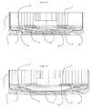
figure 2A une vue en coupe longitudinale du fond d'un conteneur selon l'invention, -
figure 2B une vue en coupe longitudinale du conteneur selon l'invention dont l'opercule est détaché, -
figure 3A une vue de dessus de la pièce de connexion selon un premier mode de réalisation, -
figure 3B une vue en élévation de la pièce de lafigure 3A , -
figure 4 , une vue de dessus de la pièce de connexion selon un deuxième mode de réalisation, et -
figure 5 , une vue de dessus de la pièce de connexion selon un troisième mode de réalisation ; -
figures 6A et 6B , des vues en perspective desfigures 2A et 2B respectivement d'un conteneur comprenant une pièce de connexion selon lesfigures 3 .
-
Figure 1A a longitudinal sectional view of the bottom of a container according to the prior art, -
Figure 1B a longitudinal sectional view of the bottom of this container, the lid of which is disconnected from the peripheral part, -
Figure 2A a longitudinal sectional view of the bottom of a container according to the invention, -
Figure 2B a longitudinal sectional view of the container according to the invention, the lid of which is detached, -
figure 3A a view from above of the connection piece according to a first embodiment, -
figure 3B an elevation view of the room from thefigure 3A , -
figure 4 a view from above of the connection piece according to a second embodiment, and -
figure 5 a top view of the connection piece according to a third embodiment; -
Figures 6A and 6B , perspective views ofFigures 2A and 2B respectively of a container comprising a connection piece according to thefigures 3 .
Le conteneur selon l'invention va maintenant être décrit. Ce conteneur comprend une paroi latérale et une paroi formant un fond en matière conductrice. La paroi formant un fond comprend une partie périphérique reliée électriquement à la paroi latérale, un opercule et une partie fragilisée autour de l'opercule joignant l'opercule à la partie périphérique. Lors d'une surpression à l'intérieur du conteneur, la partie fragilisée est conçue pour se rompre afin de laisser échapper le gaz en surpression dans le conteneur. Le conteneur contient une bague isolante électriquement, montée sur la partie périphérique. Cette bague est destinée à supporter un faisceau électrochimique. Il sert d'isolant électrique afin d'empêcher un contact électrique entre la tranche d'une électrode du faisceau et la paroi du conteneur reliée à une électrode de polarité inverse, ce qui pourrait occasionner un court-circuit interne après que le dispositif de sécurité ait été activé. Le conteneur comprend une pièce de connexion souple conductrice électriquement, en contact électrique avec l'opercule. Par pièce souple, on entend une pièce se déformant lorsque la surpression pousse l'opercule vers l'extérieur, la pièce étant fixée à l'opercule. Lors de la surpression entraînant la rupture de ladite partie fragilisée, la pièce de connexion guide l'opercule vers une position après rupture sensiblement parallèle à la position avant rupture.The container according to the invention will now be described. This container comprises a side wall and a wall forming a bottom of conductive material. The wall forming a bottom comprises a peripheral portion electrically connected to the side wall, a lid and a weakened portion around the lid joining the lid to the peripheral portion. During an overpressure inside the container, the weakened portion is designed to break in order to allow the gas to escape under pressure in the container. The container contains an electrically insulating ring mounted on the peripheral portion. This ring is intended to support an electrochemical beam. It serves as an electrical insulator to prevent electrical contact between the edge of a beam electrode and the container wall connected to a reverse polarity electrode, which could cause an internal short circuit after the safety device has been activated. The container comprises an electrically conductive flexible connection piece, in contact electric with operculum. By flexible piece is meant a piece deforming when the positive pressure pushes the cover to the outside, the part being fixed to the cover. During the overpressure resulting in the rupture of said weakened portion, the connecting piece guides the cap to a position after rupture substantially parallel to the position before rupture.
Le faisceau électrochimique est en appui sur la bague isolante et la pièce de connexion reliant électriquement le faisceau à l'opercule est souple. Le faisceau électrochimique n'est donc pas en appui sur l'opercule, mais seulement sur la partie périphérique par le biais de la bague isolante. En conséquence, suite à des chocs, le poids du faisceau n'exerce pas de force sur l'opercule et donc n'entraîne pas une rupture de la partie fragilisée. La surpression crée une force de poussée sur l'opercule dirigée vers l'extérieur du conteneur. La force de poussée entraîne la rupture de la partie fragilisée. Grâce au guidage de l'opercule vers une position parallèle à sa position avant rupture, la rupture de la partie fragilisée autour de l'opercule s'effectue totalement. En conséquence, l'opercule est assurément déconnecté de la partie périphérique. Le conteneur permet donc d'assurer la déconnexion électrique d'une électrode à sa borne associée tout en résistant aux chocs du faisceau électrochimique dans le conteneur.The electrochemical bundle bears on the insulating ring and the connection piece electrically connecting the bundle to the lid is flexible. The electrochemical beam is not supported on the lid, but only on the peripheral portion through the insulating ring. Consequently, following shocks, the weight of the beam does not exert any force on the cover and therefore does not cause a break in the weakened part. The overpressure creates a pushing force on the lid directed towards the outside of the container. The thrust force causes the fracture of the weakened part. Thanks to the guiding of the lid to a position parallel to its position before rupture, the rupture of the weakened part around the lid is completely effected. As a result, the lid is definitely disconnected from the peripheral portion. The container thus makes it possible to electrically disconnect an electrode from its associated terminal while resisting the shocks of the electrochemical bundle in the container.
Les
Sur la
Dans l'exemple des
Le faisceau comportant une alternance d'électrodes positives et négatives encadrant des séparateurs imprégnés d'électrolyte, et dans lequel les électrodes positives ou négatives sont reliées électriquement à une pièce de connexion (3) souple en matière conductrice électriquement. La pièce de connexion peut être par exemple en aluminium, car c'est une matière ayant une faible résistivité et ayant peu de résistance mécanique. Par exemple la pièce de connexion peut être en aluminium 1050. Dans la suite de la description, ce sont les électrodes positives qui sont reliées électriquement à la pièce de connexion (3). La pièce de connexion (3) fait partie du conteneur.The beam comprising an alternation of positive and negative electrodes framing separators impregnated with electrolyte, and wherein the positive or negative electrodes are electrically connected to a flexible connection piece (3) of electrically conductive material. The connecting piece can be for example aluminum, because it is a material having a low resistivity and having little mechanical strength. For example, the connection piece may be made of aluminum 1050. In the remainder of the description, it is the positive electrodes that are electrically connected to the connection piece (3). The connecting piece (3) is part of the container.
La pièce de connexion (3) comporte sur son pourtour une partie de connexion (3a) en forme d'anneau ayant une surface plane. Cette partie peut aussi avoir une forme de disque plein. La pièce de connexion (3) comporte une partie centrale (3b) ayant une surface plane parallèle à la surface de la partie de connexion (3a). Cette partie centrale (3b) est située dans un plan parallèle à la surface plane de la partie de connexion (3a). La partie de connexion (3a) et la partie centrale (3b) sont circulaires et ont le même axe. Cependant ces parties peuvent avoir d'autres formes, tel que carrée, rectangulaire etc... La pièce de connexion (3) comporte aussi des lamelles flexibles identiques (3c) reliant la partie centrale (3b) à la partie de connexion (3a). Les lamelles (3c) sont régulièrement réparties autour de la partie centrale (3b). Chaque lamelle (3c) est spiralée par rapport à la partie centrale (3b). Les quatre lamelles avec la partie centrale forment sensiblement une croix basque ou encore une croix de svastika dont les branches sont les lamelles. La pièce de connexion comporte une symétrie centrale qui est le centre de la partie centrale et de la partie de connexion. La partie centrale (3b) est fixée avec l'opercule (2b) et les électrodes positives du faisceau (5) sont reliées électriquement à cette pièce de connexion (3) par le biais de la partie de connexion (3a). Sur les
La pièce de connexion (3) est très souple et donc ne pousse pas l'opercule. Cependant la pièce de connexion peut être légèrement comprimée entre le faisceau et l'opercule de façon à ce qu'elle applique une force de 40 à 100 Newton sur l'opercule. Cette force étant connue, la partie fragilisée peut être formée de façon à ce qu'une rupture de cette partie se déclenche dés qu'une pression qui lui est exercée est égale, à la force de compression de la pièce de connexion sur l'opercule, plus la pression de la surpression pour lequel l'opercule doit s'ouvrir pour éviter un risque d'éclatement violent du conteneur et de projection de composés chimiques nocifs et corrosifs pour l'environnement et les personnes situées à proximité du conteneur. Cette pression de surpression peut être supérieure ou égale à 5 bars.The connecting piece (3) is very flexible and therefore does not push the lid. However, the connection piece can be slightly compressed between the beam and the cover so that it applies a force of 40 to 100 Newton on the cover. As this force is known, the weakened part can be formed so that a rupture of this part is triggered as soon as a pressure which is exerted on it is equal to the compressive force of the connection piece on the operculum. , plus the pressure of the overpressure for which the lid must open to avoid a risk of violent rupture of the container and the projection of harmful chemical compounds and corrosive to the environment and people in the vicinity of the container. This pressure of overpressure can be greater than or equal to 5 bars.
Selon un autre mode de réalisation, la pièce de connexion est fixée d'une part à l'opercule et d'autre part au faisceau (5) ou à la bague (4) et est montée en traction dans le conteneur. Cette force étant aussi connue, la partie fragilisée peut être formée de façon à ce qu'une rupture de cette partie se déclenche dés qu'une pression qui lui est exercée est égale, à la force de traction de la pièce de connexion sur l'opercule, moins la pression de la surpression.According to another embodiment, the connecting piece is fixed on the one hand to the cover and on the other hand to the beam (5) or the ring (4) and is mounted in tension in the container. As this force is also known, the weakened portion may be formed so that a rupture of this part is triggered as soon as a pressure exerted on it is equal to the tensile force of the connecting piece on the operculum, minus the pressure of the overpressure.
La
A la différence du premier mode de réalisation, la pièce de connexion (3) comporte seulement 3 ailettes. Les ailettes ont la même forme que les branches de la croix en forme de svastiska sauf en ce que les ailettes sont tournées vers la gauche alors que les branches de la croix en forme de svastika vers la droite. Les trois ailettes spiralées déplacent donc la partie centrale (3b) selon un mouvement hélicoïdal vers la gauche. La pièce de connexion (3) a donc une forme qui forme sensiblement une croix en forme de svastika à trois branches tournées vers la gauche.Unlike the first embodiment, the connecting piece (3) has only 3 fins. The fins have the same shape as the branches of the cross in the form of svastiska except that the wings are turned to the left while the branches of the cross shaped swastika to the right. The three spiral fins thus move the central portion (3b) in a helical movement to the left. The connecting piece (3) has a shape that substantially forms a cross shaped swastika three branches turned to the left.
La
A la différence du premier mode de réalisation, la partie de connexion (3a) et la partie centrale (3b) ont une forme carrée. Les ailettes ont la même forme que les branches de la croix de en forme de svastiska sauf en ce que les ailettes sont tournées vers la gauche alors que les branches de la croix en forme de svastika vers la droite. Les quatre ailettes spiralées déplacent donc la partie centrale (3b) selon un mouvement hélicoïdal vers la gauche. Les ailettes (3c) et la partie centrale (3b) forment sensiblement une croix en forme de svastika. La partie de connexion (3a) forme un cadre encadrant la croix en forme de svastika.Unlike the first embodiment, the connecting portion (3a) and the central portion (3b) have a square shape. The fins have the same shape as the branches of the cross in the form of svastiska except that the fins are turned to the left while the branches of the cross shaped swastika to the right. The four spiral fins thus move the central portion (3b) in a helical movement to the left. The fins (3c) and the central portion (3b) substantially form a cross shaped swastika. The connecting portion (3a) forms a frame flanking the cross in the shape of a swastika.
Le principe de fonctionnement d'un accumulateur comprenant un tel conteneur va être maintenant décrit ci-dessous. L'accumulateur comprend le conteneur décrit ci-dessus, un faisceau électrochimique (5) dans le conteneur monté sur la bague isolante (4), le faisceau (5) comportant une alternance d'électrodes négatives et positives encadrant des séparateurs imprégnés d'électrolyte, et dans lequel les électrodes positives sont reliées électriquement à la pièce de connexion (3). Le conteneur comprend en outre un couvercle muni de deux bornes de sortie de courant. Une des bornes est une borne de sortie de courant négative reliée à au moins une électrode négative dans le conteneur, et l'autre borne est une borne de sortie de courant positive reliée à au moins une électrode positive dans le conteneur par le biais de la paroi latérale (1), la paroi formant le fond (2) et la pièce de connexion (3). La connexion des électrodes peut bien entendu être inversée, c'est-à-dire que les électrodes négatives peuvent être reliées à l'une des bornes du couvercle par le biais de la pièce de connexion (3) et les parois du conteneur et les électrodes positives à l'autre borne du couvercle. Cependant, dans ce cas, la pièce de connexion doit être dans une autre matière que l'aluminium tel que cuivre, nickel ou inox. Cependant, ces matières n'ont pas les mêmes caractéristiques mécaniques notamment celle de la souplesse.The operating principle of an accumulator comprising such a container will now be described below. The accumulator comprises the container described above, an electrochemical bundle (5) in the container mounted on the insulating ring (4), the bundle (5) comprising an alternation of negative and positive electrodes surrounding electrolyte-impregnated separators and wherein the positive electrodes are electrically connected to the connection piece (3). The container further comprises a lid provided with two current output terminals. One of the terminals is a negative current output terminal connected to at least one negative electrode in the container, and the other terminal is a positive current output terminal connected to at least one positive electrode in the container through the side wall (1), the wall forming the bottom (2) and the connection piece (3). The connection of the electrodes can of course be reversed, that is to say that the negative electrodes can be connected to one of the terminals of the cover through the connecting piece (3) and the walls of the container and the positive electrodes at the other terminal of the cover. However, in this case, the connecting piece must be in a material other than aluminum such as copper, nickel or stainless steel. However, these materials do not have the same mechanical characteristics including that of flexibility.
Lors d'une surpression, par exemple due à une surcharge accidentelle, ou à un court-circuit ou à une température supérieure à la température maximale de fonctionnement, les parois du conteneur s'étirent par les forces exercées par la surpression. Cet étirement entraîne la rupture de la partie fragilisée (2c) en se déchirant entre l'opercule (2b) et la partie périphérique (2a). L'opercule (2b) se déplace donc vers l'extérieur du conteneur, la partie centrale (3b) fixée à l'opercule (2b) se déplace donc aussi vers l'extérieur du conteneur. La
Selon un autre mode de réalisation, la pièce de connexion (3) est montée à l'envers dans le conteneur. Par montage à l'envers, on entend que, c'est la partie de connexion (3a) qui est reliée à l'opercule (2b) et que c'est la partie centrale (3b) qui est reliée électriquement au faisceau (5). Le diamètre de l'opercule doit donc avoir au moins le diamètre de la partie de connexion (3a). De plus, la partie centrale (3b) peut être reliée au faisceau par le biais d'une pièce intermédiaire.According to another embodiment, the connecting piece (3) is mounted upside down in the container. By mounting in reverse, it is meant that it is the connecting part (3a) which is connected to the cover (2b) and that it is the central part (3b) which is electrically connected to the beam (5). ). The diameter of the lid must therefore have at least the diameter of the connection portion (3a). In addition, the central portion (3b) can be connected to the beam through an intermediate piece.
L'accumulateur selon l'invention trouve des applications dans le domaine de l'aviation, du spatial, de la défense, du stationnaire et de l'automobile.The accumulator according to the invention has applications in the field of aviation, space, defense, stationary and automobile.
Bien entendu, la présente invention n'est pas limitée aux exemples et au mode de réalisation décrit et représenté mais elle est susceptible à de nombreuses variantes accessibles à l'homme de l'art.Of course, the present invention is not limited to the examples and the embodiment described and shown but is susceptible to many variants accessible to those skilled in the art.
Claims (11)
Applications Claiming Priority (1)
| Application Number | Priority Date | Filing Date | Title |
|---|---|---|---|
| FR0902910A FR2946800B1 (en) | 2009-06-15 | 2009-06-15 | CONTAINER FOR WATERPROOF ACCUMULATOR |
Publications (2)
| Publication Number | Publication Date |
|---|---|
| EP2270899A1 true EP2270899A1 (en) | 2011-01-05 |
| EP2270899B1 EP2270899B1 (en) | 2014-07-16 |
Family
ID=41571132
Family Applications (1)
| Application Number | Title | Priority Date | Filing Date |
|---|---|---|---|
| EP10164390.6A Active EP2270899B1 (en) | 2009-06-15 | 2010-05-28 | Container for sealed accumulator |
Country Status (3)
| Country | Link |
|---|---|
| US (1) | US9159976B2 (en) |
| EP (1) | EP2270899B1 (en) |
| FR (1) | FR2946800B1 (en) |
Cited By (6)
| Publication number | Priority date | Publication date | Assignee | Title |
|---|---|---|---|---|
| EP2347461A2 (en) * | 2008-11-21 | 2011-07-27 | Johnson Controls Saft Advanced Power Solutions LLC | Current collector for an electrochemical cell |
| EP2541642A1 (en) * | 2011-07-01 | 2013-01-02 | Saft | Safety device for sealed battery |
| WO2013026069A1 (en) * | 2011-08-12 | 2013-02-21 | Johnson Controls Technology Llc | Current collector for an electromechanical cell |
| WO2013058974A1 (en) * | 2011-10-18 | 2013-04-25 | Johnson Controls Technology Llc | Electrochemical cell having a safety device |
| CN108767187A (en) * | 2018-05-30 | 2018-11-06 | 靖西市秀美边城农业科技有限公司 | A kind of single battery core connection structure |
| CN109564997A (en) * | 2016-08-01 | 2019-04-02 | 江森自控科技公司 | The additives for overcharge protection system of square lithium ion battery cell with neutral or non-conductive encapsulation |
Families Citing this family (2)
| Publication number | Priority date | Publication date | Assignee | Title |
|---|---|---|---|---|
| CN109565013A (en) * | 2016-08-01 | 2019-04-02 | 江森自控科技公司 | Battery unit overcharges protection component |
| WO2019179206A1 (en) * | 2018-03-23 | 2019-09-26 | Chongqing Jinkang New Energy Vehicle Co., Ltd. | Battery cell for an electric vehicle battery pack |
Citations (2)
| Publication number | Priority date | Publication date | Assignee | Title |
|---|---|---|---|---|
| US6139986A (en) * | 1997-02-17 | 2000-10-31 | Ngk Insulators, Ltd. | Lithium secondary battery |
| FR2873495A1 (en) | 2004-07-23 | 2006-01-27 | Accumulateurs Fixes | SAFETY DEVICE FOR SEALED ACCUMULATOR |
Family Cites Families (4)
| Publication number | Priority date | Publication date | Assignee | Title |
|---|---|---|---|---|
| US6284403B1 (en) * | 1997-12-18 | 2001-09-04 | Matsushita Electric Industrial Co., Ltd. | Closure assembly for sealed batteries |
| US7572545B2 (en) * | 2006-05-24 | 2009-08-11 | Everyready Battery Company, Inc. | Battery can having vent and asymmetric welded cover |
| US7875376B2 (en) * | 2006-05-24 | 2011-01-25 | Eveready Battery Company, Inc. | Battery can having off-center C-shaped vent |
| CN201584441U (en) * | 2009-08-31 | 2010-09-15 | 东莞新能源科技有限公司 | Combined cover cap of battery |
-
2009
- 2009-06-15 FR FR0902910A patent/FR2946800B1/en not_active Expired - Fee Related
-
2010
- 2010-05-28 EP EP10164390.6A patent/EP2270899B1/en active Active
- 2010-06-15 US US12/815,606 patent/US9159976B2/en active Active
Patent Citations (2)
| Publication number | Priority date | Publication date | Assignee | Title |
|---|---|---|---|---|
| US6139986A (en) * | 1997-02-17 | 2000-10-31 | Ngk Insulators, Ltd. | Lithium secondary battery |
| FR2873495A1 (en) | 2004-07-23 | 2006-01-27 | Accumulateurs Fixes | SAFETY DEVICE FOR SEALED ACCUMULATOR |
Cited By (13)
| Publication number | Priority date | Publication date | Assignee | Title |
|---|---|---|---|---|
| EP2347461A4 (en) * | 2008-11-21 | 2013-08-21 | Johnson Controls Saft Advanced | Current collector for an electrochemical cell |
| US9496557B2 (en) | 2008-11-21 | 2016-11-15 | Johnson Controls -Saft Advanced Power Solutions Llc | Current collector for an electrochemical cell |
| EP2347461A2 (en) * | 2008-11-21 | 2011-07-27 | Johnson Controls Saft Advanced Power Solutions LLC | Current collector for an electrochemical cell |
| US9099715B2 (en) | 2011-07-01 | 2015-08-04 | Saft | Safety device for a sealed accumulator |
| FR2977379A1 (en) * | 2011-07-01 | 2013-01-04 | Accumulateurs Fixes | SAFETY DEVICE FOR SEALED ACCUMULATOR |
| EP2541642A1 (en) * | 2011-07-01 | 2013-01-02 | Saft | Safety device for sealed battery |
| WO2013026069A1 (en) * | 2011-08-12 | 2013-02-21 | Johnson Controls Technology Llc | Current collector for an electromechanical cell |
| US9496539B2 (en) | 2011-08-12 | 2016-11-15 | Johnson Controls Technology Llc | Current collector for an electromechanical cell |
| WO2013058974A1 (en) * | 2011-10-18 | 2013-04-25 | Johnson Controls Technology Llc | Electrochemical cell having a safety device |
| US9196920B2 (en) | 2011-10-18 | 2015-11-24 | Johnson Controls Technology Llc | Electrochemical cell having a safety device |
| CN109564997A (en) * | 2016-08-01 | 2019-04-02 | 江森自控科技公司 | The additives for overcharge protection system of square lithium ion battery cell with neutral or non-conductive encapsulation |
| US11355823B2 (en) | 2016-08-01 | 2022-06-07 | Cps Technology Holdings Llc | Overcharge protection systems for prismatic lithium ion battery cells having neutral or non-conductive packaging |
| CN108767187A (en) * | 2018-05-30 | 2018-11-06 | 靖西市秀美边城农业科技有限公司 | A kind of single battery core connection structure |
Also Published As
| Publication number | Publication date |
|---|---|
| US9159976B2 (en) | 2015-10-13 |
| EP2270899B1 (en) | 2014-07-16 |
| FR2946800A1 (en) | 2010-12-17 |
| FR2946800B1 (en) | 2011-06-24 |
| US20100314285A1 (en) | 2010-12-16 |
Similar Documents
| Publication | Publication Date | Title |
|---|---|---|
| EP2270899B1 (en) | Container for sealed accumulator | |
| EP1626456B1 (en) | Safety device for sealed storage battery | |
| EP1705735B1 (en) | Sealed storage battery with safety device | |
| EP0890193B1 (en) | Sealed electrochemical generator equipped with a circuit-breaker terminal | |
| CN104285318B (en) | Current interrupter and electrical storage device using same | |
| EP2654105B1 (en) | System and method for detecting the opening of a seal member in a sealed accumulator | |
| JP5120638B2 (en) | Battery with current interruption mechanism | |
| EP2127000B1 (en) | Safety device for a watertight accumulator | |
| EP2337053B1 (en) | Battery cut out with active thermomechanical element | |
| EP2541642B1 (en) | Safety device for sealed battery | |
| JP2015056380A (en) | Current interrupting device and power storage device using the same | |
| JPH08293301A (en) | Safety device of secondary battery | |
| US8993139B2 (en) | Sealed secondary battery | |
| JPH10247483A (en) | Safety structure of sealed battery | |
| EP1217670A1 (en) | Safety valve to improve shelf life of a battery | |
| JP2009272162A (en) | Battery with current shut-off mechanism | |
| JP2020013692A (en) | Secondary battery | |
| JP2015125902A (en) | Power storge device |
Legal Events
| Date | Code | Title | Description |
|---|---|---|---|
| PUAI | Public reference made under article 153(3) epc to a published international application that has entered the european phase |
Free format text: ORIGINAL CODE: 0009012 |
|
| AK | Designated contracting states |
Kind code of ref document: A1 Designated state(s): AL AT BE BG CH CY CZ DE DK EE ES FI FR GB GR HR HU IE IS IT LI LT LU LV MC MK MT NL NO PL PT RO SE SI SK SM TR |
|
| AX | Request for extension of the european patent |
Extension state: BA ME RS |
|
| 17P | Request for examination filed |
Effective date: 20110705 |
|
| GRAP | Despatch of communication of intention to grant a patent |
Free format text: ORIGINAL CODE: EPIDOSNIGR1 |
|
| INTG | Intention to grant announced |
Effective date: 20140204 |
|
| GRAS | Grant fee paid |
Free format text: ORIGINAL CODE: EPIDOSNIGR3 |
|
| GRAA | (expected) grant |
Free format text: ORIGINAL CODE: 0009210 |
|
| AK | Designated contracting states |
Kind code of ref document: B1 Designated state(s): AL AT BE BG CH CY CZ DE DK EE ES FI FR GB GR HR HU IE IS IT LI LT LU LV MC MK MT NL NO PL PT RO SE SI SK SM TR |
|
| REG | Reference to a national code |
Ref country code: GB Ref legal event code: FG4D Free format text: NOT ENGLISH |
|
| REG | Reference to a national code |
Ref country code: CH Ref legal event code: EP |
|
| REG | Reference to a national code |
Ref country code: IE Ref legal event code: FG4D Free format text: LANGUAGE OF EP DOCUMENT: FRENCH |
|
| REG | Reference to a national code |
Ref country code: AT Ref legal event code: REF Ref document number: 678107 Country of ref document: AT Kind code of ref document: T Effective date: 20140815 |
|
| REG | Reference to a national code |
Ref country code: DE Ref legal event code: R096 Ref document number: 602010017437 Country of ref document: DE Effective date: 20140828 |
|
| REG | Reference to a national code |
Ref country code: NL Ref legal event code: VDEP Effective date: 20140716 |
|
| REG | Reference to a national code |
Ref country code: AT Ref legal event code: MK05 Ref document number: 678107 Country of ref document: AT Kind code of ref document: T Effective date: 20140716 |
|
| REG | Reference to a national code |
Ref country code: LT Ref legal event code: MG4D |
|
| PG25 | Lapsed in a contracting state [announced via postgrant information from national office to epo] |
Ref country code: NO Free format text: LAPSE BECAUSE OF FAILURE TO SUBMIT A TRANSLATION OF THE DESCRIPTION OR TO PAY THE FEE WITHIN THE PRESCRIBED TIME-LIMIT Effective date: 20141016 Ref country code: LT Free format text: LAPSE BECAUSE OF FAILURE TO SUBMIT A TRANSLATION OF THE DESCRIPTION OR TO PAY THE FEE WITHIN THE PRESCRIBED TIME-LIMIT Effective date: 20140716 Ref country code: GR Free format text: LAPSE BECAUSE OF FAILURE TO SUBMIT A TRANSLATION OF THE DESCRIPTION OR TO PAY THE FEE WITHIN THE PRESCRIBED TIME-LIMIT Effective date: 20141017 Ref country code: SE Free format text: LAPSE BECAUSE OF FAILURE TO SUBMIT A TRANSLATION OF THE DESCRIPTION OR TO PAY THE FEE WITHIN THE PRESCRIBED TIME-LIMIT Effective date: 20140716 Ref country code: PT Free format text: LAPSE BECAUSE OF FAILURE TO SUBMIT A TRANSLATION OF THE DESCRIPTION OR TO PAY THE FEE WITHIN THE PRESCRIBED TIME-LIMIT Effective date: 20141117 Ref country code: FI Free format text: LAPSE BECAUSE OF FAILURE TO SUBMIT A TRANSLATION OF THE DESCRIPTION OR TO PAY THE FEE WITHIN THE PRESCRIBED TIME-LIMIT Effective date: 20140716 Ref country code: BG Free format text: LAPSE BECAUSE OF FAILURE TO SUBMIT A TRANSLATION OF THE DESCRIPTION OR TO PAY THE FEE WITHIN THE PRESCRIBED TIME-LIMIT Effective date: 20141016 Ref country code: ES Free format text: LAPSE BECAUSE OF FAILURE TO SUBMIT A TRANSLATION OF THE DESCRIPTION OR TO PAY THE FEE WITHIN THE PRESCRIBED TIME-LIMIT Effective date: 20140716 |
|
| PG25 | Lapsed in a contracting state [announced via postgrant information from national office to epo] |
Ref country code: LV Free format text: LAPSE BECAUSE OF FAILURE TO SUBMIT A TRANSLATION OF THE DESCRIPTION OR TO PAY THE FEE WITHIN THE PRESCRIBED TIME-LIMIT Effective date: 20140716 Ref country code: PL Free format text: LAPSE BECAUSE OF FAILURE TO SUBMIT A TRANSLATION OF THE DESCRIPTION OR TO PAY THE FEE WITHIN THE PRESCRIBED TIME-LIMIT Effective date: 20140716 Ref country code: NL Free format text: LAPSE BECAUSE OF FAILURE TO SUBMIT A TRANSLATION OF THE DESCRIPTION OR TO PAY THE FEE WITHIN THE PRESCRIBED TIME-LIMIT Effective date: 20140716 Ref country code: IS Free format text: LAPSE BECAUSE OF FAILURE TO SUBMIT A TRANSLATION OF THE DESCRIPTION OR TO PAY THE FEE WITHIN THE PRESCRIBED TIME-LIMIT Effective date: 20141116 Ref country code: AT Free format text: LAPSE BECAUSE OF FAILURE TO SUBMIT A TRANSLATION OF THE DESCRIPTION OR TO PAY THE FEE WITHIN THE PRESCRIBED TIME-LIMIT Effective date: 20140716 Ref country code: CY Free format text: LAPSE BECAUSE OF FAILURE TO SUBMIT A TRANSLATION OF THE DESCRIPTION OR TO PAY THE FEE WITHIN THE PRESCRIBED TIME-LIMIT Effective date: 20140716 |
|
| REG | Reference to a national code |
Ref country code: DE Ref legal event code: R097 Ref document number: 602010017437 Country of ref document: DE |
|
| PG25 | Lapsed in a contracting state [announced via postgrant information from national office to epo] |
Ref country code: DK Free format text: LAPSE BECAUSE OF FAILURE TO SUBMIT A TRANSLATION OF THE DESCRIPTION OR TO PAY THE FEE WITHIN THE PRESCRIBED TIME-LIMIT Effective date: 20140716 Ref country code: CZ Free format text: LAPSE BECAUSE OF FAILURE TO SUBMIT A TRANSLATION OF THE DESCRIPTION OR TO PAY THE FEE WITHIN THE PRESCRIBED TIME-LIMIT Effective date: 20140716 Ref country code: RO Free format text: LAPSE BECAUSE OF FAILURE TO SUBMIT A TRANSLATION OF THE DESCRIPTION OR TO PAY THE FEE WITHIN THE PRESCRIBED TIME-LIMIT Effective date: 20140716 Ref country code: SK Free format text: LAPSE BECAUSE OF FAILURE TO SUBMIT A TRANSLATION OF THE DESCRIPTION OR TO PAY THE FEE WITHIN THE PRESCRIBED TIME-LIMIT Effective date: 20140716 Ref country code: IT Free format text: LAPSE BECAUSE OF FAILURE TO SUBMIT A TRANSLATION OF THE DESCRIPTION OR TO PAY THE FEE WITHIN THE PRESCRIBED TIME-LIMIT Effective date: 20140716 Ref country code: EE Free format text: LAPSE BECAUSE OF FAILURE TO SUBMIT A TRANSLATION OF THE DESCRIPTION OR TO PAY THE FEE WITHIN THE PRESCRIBED TIME-LIMIT Effective date: 20140716 |
|
| PLBE | No opposition filed within time limit |
Free format text: ORIGINAL CODE: 0009261 |
|
| STAA | Information on the status of an ep patent application or granted ep patent |
Free format text: STATUS: NO OPPOSITION FILED WITHIN TIME LIMIT |
|
| 26N | No opposition filed |
Effective date: 20150417 |
|
| PG25 | Lapsed in a contracting state [announced via postgrant information from national office to epo] |
Ref country code: SI Free format text: LAPSE BECAUSE OF FAILURE TO SUBMIT A TRANSLATION OF THE DESCRIPTION OR TO PAY THE FEE WITHIN THE PRESCRIBED TIME-LIMIT Effective date: 20140716 |
|
| REG | Reference to a national code |
Ref country code: CH Ref legal event code: PL |
|
| GBPC | Gb: european patent ceased through non-payment of renewal fee |
Effective date: 20150528 |
|
| PG25 | Lapsed in a contracting state [announced via postgrant information from national office to epo] |
Ref country code: CH Free format text: LAPSE BECAUSE OF NON-PAYMENT OF DUE FEES Effective date: 20150531 Ref country code: LU Free format text: LAPSE BECAUSE OF FAILURE TO SUBMIT A TRANSLATION OF THE DESCRIPTION OR TO PAY THE FEE WITHIN THE PRESCRIBED TIME-LIMIT Effective date: 20150528 Ref country code: MC Free format text: LAPSE BECAUSE OF FAILURE TO SUBMIT A TRANSLATION OF THE DESCRIPTION OR TO PAY THE FEE WITHIN THE PRESCRIBED TIME-LIMIT Effective date: 20140716 Ref country code: LI Free format text: LAPSE BECAUSE OF NON-PAYMENT OF DUE FEES Effective date: 20150531 |
|
| REG | Reference to a national code |
Ref country code: IE Ref legal event code: MM4A |
|
| PG25 | Lapsed in a contracting state [announced via postgrant information from national office to epo] |
Ref country code: GB Free format text: LAPSE BECAUSE OF NON-PAYMENT OF DUE FEES Effective date: 20150528 Ref country code: IE Free format text: LAPSE BECAUSE OF NON-PAYMENT OF DUE FEES Effective date: 20150528 |
|
| REG | Reference to a national code |
Ref country code: FR Ref legal event code: PLFP Year of fee payment: 7 |
|
| PG25 | Lapsed in a contracting state [announced via postgrant information from national office to epo] |
Ref country code: MT Free format text: LAPSE BECAUSE OF FAILURE TO SUBMIT A TRANSLATION OF THE DESCRIPTION OR TO PAY THE FEE WITHIN THE PRESCRIBED TIME-LIMIT Effective date: 20140716 |
|
| REG | Reference to a national code |
Ref country code: FR Ref legal event code: PLFP Year of fee payment: 8 |
|
| PG25 | Lapsed in a contracting state [announced via postgrant information from national office to epo] |
Ref country code: HU Free format text: LAPSE BECAUSE OF FAILURE TO SUBMIT A TRANSLATION OF THE DESCRIPTION OR TO PAY THE FEE WITHIN THE PRESCRIBED TIME-LIMIT; INVALID AB INITIO Effective date: 20100528 Ref country code: SM Free format text: LAPSE BECAUSE OF FAILURE TO SUBMIT A TRANSLATION OF THE DESCRIPTION OR TO PAY THE FEE WITHIN THE PRESCRIBED TIME-LIMIT Effective date: 20140716 |
|
| PG25 | Lapsed in a contracting state [announced via postgrant information from national office to epo] |
Ref country code: BE Free format text: LAPSE BECAUSE OF NON-PAYMENT OF DUE FEES Effective date: 20150531 Ref country code: HR Free format text: LAPSE BECAUSE OF FAILURE TO SUBMIT A TRANSLATION OF THE DESCRIPTION OR TO PAY THE FEE WITHIN THE PRESCRIBED TIME-LIMIT Effective date: 20140716 |
|
| PG25 | Lapsed in a contracting state [announced via postgrant information from national office to epo] |
Ref country code: TR Free format text: LAPSE BECAUSE OF FAILURE TO SUBMIT A TRANSLATION OF THE DESCRIPTION OR TO PAY THE FEE WITHIN THE PRESCRIBED TIME-LIMIT Effective date: 20140716 |
|
| REG | Reference to a national code |
Ref country code: FR Ref legal event code: PLFP Year of fee payment: 9 |
|
| PG25 | Lapsed in a contracting state [announced via postgrant information from national office to epo] |
Ref country code: MK Free format text: LAPSE BECAUSE OF FAILURE TO SUBMIT A TRANSLATION OF THE DESCRIPTION OR TO PAY THE FEE WITHIN THE PRESCRIBED TIME-LIMIT Effective date: 20140716 |
|
| PG25 | Lapsed in a contracting state [announced via postgrant information from national office to epo] |
Ref country code: AL Free format text: LAPSE BECAUSE OF FAILURE TO SUBMIT A TRANSLATION OF THE DESCRIPTION OR TO PAY THE FEE WITHIN THE PRESCRIBED TIME-LIMIT Effective date: 20140716 |
|
| REG | Reference to a national code |
Ref country code: DE Ref legal event code: R079 Ref document number: 602010017437 Country of ref document: DE Free format text: PREVIOUS MAIN CLASS: H01M0002120000 Ipc: H01M0050300000 |
|
| P01 | Opt-out of the competence of the unified patent court (upc) registered |
Effective date: 20230506 |
|
| PGFP | Annual fee paid to national office [announced via postgrant information from national office to epo] |
Ref country code: FR Payment date: 20230512 Year of fee payment: 14 Ref country code: DE Payment date: 20230530 Year of fee payment: 14 |