EP0959291A2 - Rohrkupplung - Google Patents
Rohrkupplung Download PDFInfo
- Publication number
- EP0959291A2 EP0959291A2 EP99108854A EP99108854A EP0959291A2 EP 0959291 A2 EP0959291 A2 EP 0959291A2 EP 99108854 A EP99108854 A EP 99108854A EP 99108854 A EP99108854 A EP 99108854A EP 0959291 A2 EP0959291 A2 EP 0959291A2
- Authority
- EP
- European Patent Office
- Prior art keywords
- plug
- pipeline
- pipe
- receptacle
- pipe according
- Prior art date
- Legal status (The legal status is an assumption and is not a legal conclusion. Google has not performed a legal analysis and makes no representation as to the accuracy of the status listed.)
- Withdrawn
Links
Images

Classifications
-
- F—MECHANICAL ENGINEERING; LIGHTING; HEATING; WEAPONS; BLASTING
- F16—ENGINEERING ELEMENTS AND UNITS; GENERAL MEASURES FOR PRODUCING AND MAINTAINING EFFECTIVE FUNCTIONING OF MACHINES OR INSTALLATIONS; THERMAL INSULATION IN GENERAL
- F16L—PIPES; JOINTS OR FITTINGS FOR PIPES; SUPPORTS FOR PIPES, CABLES OR PROTECTIVE TUBING; MEANS FOR THERMAL INSULATION IN GENERAL
- F16L37/00—Couplings of the quick-acting type
- F16L37/08—Couplings of the quick-acting type in which the connection between abutting or axially overlapping ends is maintained by locking members
- F16L37/12—Couplings of the quick-acting type in which the connection between abutting or axially overlapping ends is maintained by locking members using hooks, pawls or other movable or insertable locking members
- F16L37/14—Joints secured by inserting between mating surfaces an element, e.g. a piece of wire, a pin, a chain
- F16L37/142—Joints secured by inserting between mating surfaces an element, e.g. a piece of wire, a pin, a chain where the securing element is inserted tangentially
- F16L37/144—Joints secured by inserting between mating surfaces an element, e.g. a piece of wire, a pin, a chain where the securing element is inserted tangentially the securing element being U-shaped
Definitions
- the invention relates to a pipeline, preferably for hydraulic lines, with a plug that is used to connect the pipeline to a Pipe connection, preferably a hydraulic connection, in one plug-in direction essentially parallel to the longitudinal extension of the pipeline in a Receiving the pipe connection is insertable, with a sealing element to seal the receptacle against the pipeline when plugged in Plug, and with a support surface on the plug with the plug inserted against the plugging direction on a securing element of the receptacle supporting against pulling out can be secured, the support surface in the direction of insertion is arranged behind the sealing element.
- Such a pipeline is known from the prior art.
- the pipeline and the plug are made of steel and are at a transition point soldered together.
- the plug is essentially cylindrical and has one Circumferential groove in which the sealing element is received.
- To connect the Pipe with a pipe connection becomes the pipe with the plug inserted in the receptacle of the pipe connection in the direction of insertion.
- a securing clip is attached through which a Form fit between the receptacle and the support surface of the connector becomes. In this way it can be prevented that the plug is unwanted is pulled out.
- the plug is supported on the receptacle in the direction of insertion yourself. As a result, the connector and the pipe performance in the receptacle are axial fixed.
- a disadvantage of such pipelines is that the connector with the pipeline is soldered. As a result, the pipeline and the plug must be off be made of the same material. Due to the manufacturing process, the Coat the pipeline with a surface coating after the soldering process as an existing coating of the tube due to the soldering process would be destroyed. This increases the number of necessary Process steps to manufacture the pipeline with the connector, whereby manufacturing costs also increase. The material selection is also from Pipeline and connector severely restricted due to the soldering process.
- the object of the invention is therefore a pipeline of the aforementioned Art to develop in such a way that the soldering process can be eliminated and Pipelines with surface coating can also be used. At the same time, the manufacture of the pipeline with a plug is to be greatly simplified become.
- the object is achieved in a pipeline of the type mentioned in the introduction solved in that the plug is slidable on the pipeline and the sealing element is attached directly to the pipeline, and that between Sealing element and plug a support device firmly connected to the pipeline to support the connector on the pipeline in the direction of insertion is provided.
- This solution is simple and has the advantage that there is no more soldering between the plug and the pipeline is required. Instead it is Plug slidably attached to the pipeline. This allows plugs and piping can be made from different materials. Also already coated pipes can be used. Because the seal is attached directly to the pipeline, is movable despite the a plug between the pipeline mounted on the pipeline and reception guaranteed.
- the pipeline according to the invention can be based on manufacture the lower number of work steps inexpensively.
- the connector can be made of material that is particularly easy to process is.
- the pipeline can be a steel pipe be trained. Then the pipeline can be used in particular as a hydraulic line use.
- plugs and Pipeline according to the requirements placed on it with regard to optimize the material selection.
- the connector is made of plastic.
- Plastic is particularly easy to work with and makes it particularly easy inexpensive manufacture of the connector. It can also be done easily Realize complicated forms of the plug.
- the support device can be annular circumferential support ring are formed on the circumference of the pipeline. Then can be a particularly uniform contact of the plug on the support device realize.
- the support ring can be annular circumferential flange of the steel tube are formed. Then the support ring can be removed train integrally with the steel tube and can already during manufacture of the steel pipe are generated. The flare is compressed by compressing the End piece of the steel tube generated so that an annular flange is formed.
- a second flange can be provided and the sealing element be arranged between the two flanges. This is also a guide of the sealing element possible in the axial direction.
- the sealing element is an O-ring
- the Outer diameter of the O-ring at least when not plugged in of the plug is larger than the outside diameter of the flange. This ensures that the O-ring develops its sealing effect when the plug is inserted.
- the support surface of the plug are formed by a preferably groove-shaped fuse holder, into which the securing element can preferably be inserted perpendicular to the direction of insertion is.
- the connector can be positively in the axial direction both in the direction of insertion and against the direction of insertion in the receptacle establish.
- the securing element acts as a securing clip is formed which through an opening in the receptacle in the Fuse holder of the plug can be inserted to ensure a positive connection between To achieve recording, securing clip and connector. In this way can be easily installed to secure the connector in the receptacle realize.
- the plug can essentially be cylindrical. Then the plug can be manufactured particularly easily.
- the plug can have a guide section whose outer diameter at least in sections essentially the inside diameter corresponds to the recording. This allows radial guidance of the plug realize in the recording.
- the guide section near the support ring is arranged between the support surface and the support ring. Then the connector can be removed easier to insert into the holder.
- a clutch for connecting a pipe with a pipe connection, with one in the pipe connection arranged receptacle for inserting the one having a connector Pipeline and with a securing element to secure the Plug with the pipeline against pulling out of the receptacle, marked through a pipeline according to one of claims 1 to 12.
- the pipeline 1 from the prior art consists of a pipe 2 Steel and also made of steel by machining processes Connector 3.
- the tube 2 and the connector 3 are at the solder joint 4 with each other soldered.
- the plug 3 has a recess 5, the inner diameter of which is essentially corresponds to the outside diameter of the tube 2 and into which the tube 2 is partially inserted, as can be seen from FIG. 1. Located in connector 3 a through hole 6, which opens into the tube 2.
- the plug 3 has a sealing groove 7, which is on the circumference of the plug 3 runs and receives an O-ring 8.
- the plug 3 has a on the circumference extending groove 9, which has a support surface 10.
- the support surface 10 is the wall of the securing groove 9.
- the pipeline is partially schematic Pipe connection 11 shown in a in this insertion direction E inserted state shown.
- the pipe connection 11 has a housing 12 with a receptacle 13 in which the plug in the insertion direction E is insertable.
- the housing 12 has a through hole 14, which in the through hole 6 opens, or is flush with this.
- Two openings 15 designed as insertion slots are provided on the housing 12, in which a securing element perpendicular to the longitudinal extension of the Pipeline can be inserted.
- the securing element is as a securing clip 16 formed, which is resilient and has two curved arms 17, the enclose the securing groove 9
- the securing clip 16 is through the openings 15 removable from the housing 12 or inserted into this. in the inserted condition of the securing clip is the connector 3 in the axial direction the pipeline in the housing.
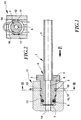
- Fig. 3 the pipe is also inserted into a pipe connection 11 Condition shown.
- the plug 3 is displaceable in the axial direction on the Pipe 2 stored.
- the tube 2 is also made of steel and is provided with two flanges 18 and 19.
- the O-ring 8 is no longer in a sealing groove between the flanges 7 of the plug 3 arranged, but directly on the tube 2 itself and thereby seals between the receptacle 13 of the housing 12 and the tube 2 from.
- the receptacle 13 is dimensioned so that the pipe can be inserted and after there is very little play in the direction of insertion.
- the connector 3 is no longer made of steel, but of plastic and has a securing groove 9 with a support surface 10.
- the housing 12 also has two openings 15, into which a securing clip 16 is inserted, into the securing groove 9 engages and thereby secures the connector in the axial direction.
- the backup takes place thereby form-fitting between housing 12 and connector 3.
- the flange 18, which is arranged between the O-ring and plug 3, forms a support ring which the tube 2 is supported against the plug-in direction E on the connector 3.
- the plug 3 also has a guide section 20, the Outer diameter essentially the inner diameter of the receptacle 13 corresponds. As a result, the pipeline is guided radially.
- the pipe 1 with the plug 3 forms together with the pipe connection 11 a clutch 21.
- the pipeline 1 is a hydraulic pipeline and the pipeline connection 11 around a hydraulic connection of e.g. a hydraulic cylinder or similar.
- the pipe 2 does not have to be a completely rigid pipe act, a flexible pipe can also be used. It can also do that Tube in the area of the connector and be fixed to a hose or the like be connected.
- the coupling according to the invention can not only be used use to connect a pipe to a pipe connection, but also e.g. to connect two pipes together.
- the connecting piece of a pipe may be provided with a receptacle 13 similar to the housing 12 and the other pipe as the invention Pipeline to be formed. When two opposite ones are arranged Recordings 13 can also two pipes according to the invention together get connected.
- the pipeline according to the invention can already be coated beforehand Pipes are used which are already provided with the flanges 18 and 19.
- the connector 3, which is made of plastic, can be made separately and be attached to the tube 2. In this way, soldering processes or the like avoided for connecting pipe and plug.
Applications Claiming Priority (2)
| Application Number | Priority Date | Filing Date | Title |
|---|---|---|---|
| DE19822753 | 1998-05-20 | ||
| DE1998122753 DE19822753A1 (de) | 1998-05-20 | 1998-05-20 | Rohrleitung |
Publications (2)
| Publication Number | Publication Date |
|---|---|
| EP0959291A2 true EP0959291A2 (de) | 1999-11-24 |
| EP0959291A3 EP0959291A3 (de) | 1999-12-15 |
Family
ID=7868488
Family Applications (1)
| Application Number | Title | Priority Date | Filing Date |
|---|---|---|---|
| EP99108854A Withdrawn EP0959291A3 (de) | 1998-05-20 | 1999-05-04 | Rohrkupplung |
Country Status (4)
| Country | Link |
|---|---|
| EP (1) | EP0959291A3 (es) |
| BR (1) | BR9901554A (es) |
| CA (1) | CA2272016A1 (es) |
| DE (1) | DE19822753A1 (es) |
Cited By (4)
| Publication number | Priority date | Publication date | Assignee | Title |
|---|---|---|---|---|
| EP1701082A1 (de) * | 2005-03-10 | 2006-09-13 | FTE automotive GmbH | Endabschnitt einer Fluidleitung mit angeformter Steckarmatur |
| FR3001024A1 (fr) * | 2013-01-17 | 2014-07-18 | Delphi Automotive Systems Lux | Dispositif de connexion rapide. |
| CN109029622A (zh) * | 2018-05-28 | 2018-12-18 | 佛山市川东磁电股份有限公司 | 一种车用尿素液位传感器与接头的连接结构 |
| CN110216920A (zh) * | 2019-06-18 | 2019-09-10 | 安徽猛牛彩印包装有限公司 | 一种用于制袋机上的切段废料收纳高效处理装置 |
Families Citing this family (4)
| Publication number | Priority date | Publication date | Assignee | Title |
|---|---|---|---|---|
| DE102004044917A1 (de) * | 2004-09-14 | 2006-03-16 | Fte Automotive Gmbh | Lösbare Steckverbindung für Rohrleitungen od. dgl. |
| DE102005050490A1 (de) * | 2005-10-21 | 2007-04-26 | Henn Gmbh & Co. Kg | Steckverbindung an Rohren und Schläuchen mit einem Rohrrastring |
| DE102014214186A1 (de) * | 2014-07-22 | 2016-01-28 | Schaeffler Technologies AG & Co. KG | Verbindungsvorrichtung |
| DE102022114275A1 (de) | 2022-06-07 | 2023-12-07 | Valeo Powertrain Gmbh | Sensor und Sensorbaugruppe |
Family Cites Families (4)
| Publication number | Priority date | Publication date | Assignee | Title |
|---|---|---|---|---|
| DE2028712A1 (de) * | 1970-06-11 | 1971-12-16 | Kessler & Co Tech Chem Gmbh | Losbare Rohr oder Schlauchkupplung |
| DE3531926A1 (de) * | 1985-09-07 | 1987-03-19 | Kugelfischer G Schaefer & Co | Loesbare steckverbindung |
| US4874174A (en) * | 1987-03-05 | 1989-10-17 | Aisin Seiki Kabushiki Kaisha | Tube connecting unit |
| US5275448A (en) * | 1991-09-10 | 1994-01-04 | Huron Products Industries, Inc. | Quick connect tubing connector and method of assembly |
-
1998
- 1998-05-20 DE DE1998122753 patent/DE19822753A1/de not_active Ceased
-
1999
- 1999-05-04 EP EP99108854A patent/EP0959291A3/de not_active Withdrawn
- 1999-05-17 CA CA 2272016 patent/CA2272016A1/en not_active Abandoned
- 1999-05-19 BR BR9901554A patent/BR9901554A/pt not_active Application Discontinuation
Non-Patent Citations (1)
| Title |
|---|
| None |
Cited By (6)
| Publication number | Priority date | Publication date | Assignee | Title |
|---|---|---|---|---|
| EP1701082A1 (de) * | 2005-03-10 | 2006-09-13 | FTE automotive GmbH | Endabschnitt einer Fluidleitung mit angeformter Steckarmatur |
| FR3001024A1 (fr) * | 2013-01-17 | 2014-07-18 | Delphi Automotive Systems Lux | Dispositif de connexion rapide. |
| WO2014111214A1 (fr) * | 2013-01-17 | 2014-07-24 | Delphi Automotive Systems Luxembourg Sa | Dispositif de connexion rapide |
| US10502347B2 (en) | 2013-01-17 | 2019-12-10 | Mahle International Gmbh | Quick connector device |
| CN109029622A (zh) * | 2018-05-28 | 2018-12-18 | 佛山市川东磁电股份有限公司 | 一种车用尿素液位传感器与接头的连接结构 |
| CN110216920A (zh) * | 2019-06-18 | 2019-09-10 | 安徽猛牛彩印包装有限公司 | 一种用于制袋机上的切段废料收纳高效处理装置 |
Also Published As
| Publication number | Publication date |
|---|---|
| DE19822753A1 (de) | 1999-12-02 |
| CA2272016A1 (en) | 1999-11-20 |
| EP0959291A3 (de) | 1999-12-15 |
| BR9901554A (pt) | 2000-02-22 |
Similar Documents
| Publication | Publication Date | Title |
|---|---|---|
| DE2832614C2 (de) | Verbindungsstück für Rohrleitungen | |
| EP0743479B1 (de) | Anordnung zum Anschluss eines Metallrohrs an eine Aufnahmehülse | |
| DE2921568A1 (de) | Steckverbindungs-anschlusstueck fuer druckluftbremsanlagen | |
| AT3080U1 (de) | Vorrichtung zum verbinden eines rohrstutzens, rohrförmigen armaturenteils oder fittings mit einem rohr | |
| EP0214395A1 (de) | Elastische Rohrverbindung, insbesondere flexible Rohrkupplung | |
| AT410706B (de) | Anschlussvorrichtung für ein kunststoffrohr | |
| EP0615089A1 (de) | Lösbare Steckverbindung für Hochdruckleitungen | |
| EP0959291A2 (de) | Rohrkupplung | |
| DE4117932C2 (es) | ||
| DE3923579A1 (de) | Anschlussarmatur fuer rohre, insbesondere fuer kunststoffrohre | |
| DE19614684A1 (de) | Vorrichtung zur Verbindung von Rohren oder dergleichen rohrförmigen Armaturenteilen mit einer Armatur für fluide Medien | |
| DE102005044751A1 (de) | Steckverbinder für Medienleitungen | |
| DE2002826A1 (de) | Kupplungsstueck fuer Roehren oder Schlaeuche | |
| DE10347927B4 (de) | Verfahren und Vorrichtung zur Herstellung einer Rohrpressverbindung an einer Steckverbindung | |
| CH581273A5 (en) | Snap connection between hose ends - has inner and outer sleeves with O-ring seal and finger with ridge and groove | |
| DE19927591B4 (de) | Vorrichtung zum dichtschließenden Verbinden eines Kanalrohres mit einem Anschlußrohr | |
| DE102007049996A1 (de) | Rohrverbindung | |
| DE8610238U1 (de) | Schlauch-Steck-Kupplung für Elektro-Schutzschlauch-Verschraubungen | |
| DE10130003A1 (de) | Rohrverbinder | |
| DE10031729C2 (de) | Steckverbindung zwischen einem ringgewellten Schlauch und einem Glattrohr | |
| DE2600621C3 (de) | Gewindelose Verbindung für Rohre und Verfahren zu ihrer Herstellung | |
| DE102019110315A1 (de) | Hausanschlussanordnung | |
| DE2752761C2 (de) | Verfahren zum Herstellen einer Schnellkupplung | |
| DE10113354B4 (de) | Reparaturteil für Wellrohre | |
| CH686798A5 (de) | Steckmuffe. |
Legal Events
| Date | Code | Title | Description |
|---|---|---|---|
| PUAI | Public reference made under article 153(3) epc to a published international application that has entered the european phase |
Free format text: ORIGINAL CODE: 0009012 |
|
| PUAL | Search report despatched |
Free format text: ORIGINAL CODE: 0009013 |
|
| AK | Designated contracting states |
Kind code of ref document: A2 Designated state(s): DE ES FR GB IT |
|
| AX | Request for extension of the european patent |
Free format text: AL;LT;LV;MK;RO;SI |
|
| AK | Designated contracting states |
Kind code of ref document: A3 Designated state(s): AT BE CH CY DE DK ES FI FR GB GR IE IT LI LU MC NL PT SE |
|
| AX | Request for extension of the european patent |
Free format text: AL;LT;LV;MK;RO;SI |
|
| 17P | Request for examination filed |
Effective date: 20000605 |
|
| AKX | Designation fees paid |
Free format text: DE ES FR GB IT |
|
| STAA | Information on the status of an ep patent application or granted ep patent |
Free format text: STATUS: THE APPLICATION HAS BEEN WITHDRAWN |
|
| 18W | Application withdrawn |
Withdrawal date: 20001009 |