EP0959291A2 - Pipe coupling - Google Patents
Pipe coupling Download PDFInfo
- Publication number
- EP0959291A2 EP0959291A2 EP99108854A EP99108854A EP0959291A2 EP 0959291 A2 EP0959291 A2 EP 0959291A2 EP 99108854 A EP99108854 A EP 99108854A EP 99108854 A EP99108854 A EP 99108854A EP 0959291 A2 EP0959291 A2 EP 0959291A2
- Authority
- EP
- European Patent Office
- Prior art keywords
- plug
- pipeline
- pipe
- receptacle
- pipe according
- Prior art date
- Legal status (The legal status is an assumption and is not a legal conclusion. Google has not performed a legal analysis and makes no representation as to the accuracy of the status listed.)
- Withdrawn
Links
- 230000008878 coupling Effects 0.000 title claims description 3
- 238000010168 coupling process Methods 0.000 title claims description 3
- 238000005859 coupling reaction Methods 0.000 title claims description 3
- 238000003780 insertion Methods 0.000 claims description 19
- 230000037431 insertion Effects 0.000 claims description 19
- 238000007789 sealing Methods 0.000 claims description 18
- 229910000831 Steel Inorganic materials 0.000 claims description 11
- 239000010959 steel Substances 0.000 claims description 11
- 239000000463 material Substances 0.000 claims description 9
- 238000004519 manufacturing process Methods 0.000 description 7
- 238000000034 method Methods 0.000 description 7
- 238000005476 soldering Methods 0.000 description 6
- 239000011248 coating agent Substances 0.000 description 3
- 238000000576 coating method Methods 0.000 description 3
- 230000000694 effects Effects 0.000 description 3
- 238000005516 engineering process Methods 0.000 description 1
- 238000003754 machining Methods 0.000 description 1
- 229910000679 solder Inorganic materials 0.000 description 1
- 230000007704 transition Effects 0.000 description 1
Images

Classifications
-
- F—MECHANICAL ENGINEERING; LIGHTING; HEATING; WEAPONS; BLASTING
- F16—ENGINEERING ELEMENTS AND UNITS; GENERAL MEASURES FOR PRODUCING AND MAINTAINING EFFECTIVE FUNCTIONING OF MACHINES OR INSTALLATIONS; THERMAL INSULATION IN GENERAL
- F16L—PIPES; JOINTS OR FITTINGS FOR PIPES; SUPPORTS FOR PIPES, CABLES OR PROTECTIVE TUBING; MEANS FOR THERMAL INSULATION IN GENERAL
- F16L37/00—Couplings of the quick-acting type
- F16L37/08—Couplings of the quick-acting type in which the connection between abutting or axially overlapping ends is maintained by locking members
- F16L37/12—Couplings of the quick-acting type in which the connection between abutting or axially overlapping ends is maintained by locking members using hooks, pawls, or other movable or insertable locking members
- F16L37/14—Joints secured by inserting between mating surfaces an element, e.g. a piece of wire, a pin, a chain
- F16L37/142—Joints secured by inserting between mating surfaces an element, e.g. a piece of wire, a pin, a chain where the securing element is inserted tangentially
- F16L37/144—Joints secured by inserting between mating surfaces an element, e.g. a piece of wire, a pin, a chain where the securing element is inserted tangentially the securing element being U-shaped
Definitions
- the invention relates to a pipeline, preferably for hydraulic lines, with a plug that is used to connect the pipeline to a Pipe connection, preferably a hydraulic connection, in one plug-in direction essentially parallel to the longitudinal extension of the pipeline in a Receiving the pipe connection is insertable, with a sealing element to seal the receptacle against the pipeline when plugged in Plug, and with a support surface on the plug with the plug inserted against the plugging direction on a securing element of the receptacle supporting against pulling out can be secured, the support surface in the direction of insertion is arranged behind the sealing element.
- Such a pipeline is known from the prior art.
- the pipeline and the plug are made of steel and are at a transition point soldered together.
- the plug is essentially cylindrical and has one Circumferential groove in which the sealing element is received.
- To connect the Pipe with a pipe connection becomes the pipe with the plug inserted in the receptacle of the pipe connection in the direction of insertion.
- a securing clip is attached through which a Form fit between the receptacle and the support surface of the connector becomes. In this way it can be prevented that the plug is unwanted is pulled out.
- the plug is supported on the receptacle in the direction of insertion yourself. As a result, the connector and the pipe performance in the receptacle are axial fixed.
- a disadvantage of such pipelines is that the connector with the pipeline is soldered. As a result, the pipeline and the plug must be off be made of the same material. Due to the manufacturing process, the Coat the pipeline with a surface coating after the soldering process as an existing coating of the tube due to the soldering process would be destroyed. This increases the number of necessary Process steps to manufacture the pipeline with the connector, whereby manufacturing costs also increase. The material selection is also from Pipeline and connector severely restricted due to the soldering process.
- the object of the invention is therefore a pipeline of the aforementioned Art to develop in such a way that the soldering process can be eliminated and Pipelines with surface coating can also be used. At the same time, the manufacture of the pipeline with a plug is to be greatly simplified become.
- the object is achieved in a pipeline of the type mentioned in the introduction solved in that the plug is slidable on the pipeline and the sealing element is attached directly to the pipeline, and that between Sealing element and plug a support device firmly connected to the pipeline to support the connector on the pipeline in the direction of insertion is provided.
- This solution is simple and has the advantage that there is no more soldering between the plug and the pipeline is required. Instead it is Plug slidably attached to the pipeline. This allows plugs and piping can be made from different materials. Also already coated pipes can be used. Because the seal is attached directly to the pipeline, is movable despite the a plug between the pipeline mounted on the pipeline and reception guaranteed.
- the pipeline according to the invention can be based on manufacture the lower number of work steps inexpensively.
- the connector can be made of material that is particularly easy to process is.
- the pipeline can be a steel pipe be trained. Then the pipeline can be used in particular as a hydraulic line use.
- plugs and Pipeline according to the requirements placed on it with regard to optimize the material selection.
- the connector is made of plastic.
- Plastic is particularly easy to work with and makes it particularly easy inexpensive manufacture of the connector. It can also be done easily Realize complicated forms of the plug.
- the support device can be annular circumferential support ring are formed on the circumference of the pipeline. Then can be a particularly uniform contact of the plug on the support device realize.
- the support ring can be annular circumferential flange of the steel tube are formed. Then the support ring can be removed train integrally with the steel tube and can already during manufacture of the steel pipe are generated. The flare is compressed by compressing the End piece of the steel tube generated so that an annular flange is formed.
- a second flange can be provided and the sealing element be arranged between the two flanges. This is also a guide of the sealing element possible in the axial direction.
- the sealing element is an O-ring
- the Outer diameter of the O-ring at least when not plugged in of the plug is larger than the outside diameter of the flange. This ensures that the O-ring develops its sealing effect when the plug is inserted.
- the support surface of the plug are formed by a preferably groove-shaped fuse holder, into which the securing element can preferably be inserted perpendicular to the direction of insertion is.
- the connector can be positively in the axial direction both in the direction of insertion and against the direction of insertion in the receptacle establish.
- the securing element acts as a securing clip is formed which through an opening in the receptacle in the Fuse holder of the plug can be inserted to ensure a positive connection between To achieve recording, securing clip and connector. In this way can be easily installed to secure the connector in the receptacle realize.
- the plug can essentially be cylindrical. Then the plug can be manufactured particularly easily.
- the plug can have a guide section whose outer diameter at least in sections essentially the inside diameter corresponds to the recording. This allows radial guidance of the plug realize in the recording.
- the guide section near the support ring is arranged between the support surface and the support ring. Then the connector can be removed easier to insert into the holder.
- a clutch for connecting a pipe with a pipe connection, with one in the pipe connection arranged receptacle for inserting the one having a connector Pipeline and with a securing element to secure the Plug with the pipeline against pulling out of the receptacle, marked through a pipeline according to one of claims 1 to 12.
- the pipeline 1 from the prior art consists of a pipe 2 Steel and also made of steel by machining processes Connector 3.
- the tube 2 and the connector 3 are at the solder joint 4 with each other soldered.
- the plug 3 has a recess 5, the inner diameter of which is essentially corresponds to the outside diameter of the tube 2 and into which the tube 2 is partially inserted, as can be seen from FIG. 1. Located in connector 3 a through hole 6, which opens into the tube 2.
- the plug 3 has a sealing groove 7, which is on the circumference of the plug 3 runs and receives an O-ring 8.
- the plug 3 has a on the circumference extending groove 9, which has a support surface 10.
- the support surface 10 is the wall of the securing groove 9.
- the pipeline is partially schematic Pipe connection 11 shown in a in this insertion direction E inserted state shown.
- the pipe connection 11 has a housing 12 with a receptacle 13 in which the plug in the insertion direction E is insertable.
- the housing 12 has a through hole 14, which in the through hole 6 opens, or is flush with this.
- Two openings 15 designed as insertion slots are provided on the housing 12, in which a securing element perpendicular to the longitudinal extension of the Pipeline can be inserted.
- the securing element is as a securing clip 16 formed, which is resilient and has two curved arms 17, the enclose the securing groove 9
- the securing clip 16 is through the openings 15 removable from the housing 12 or inserted into this. in the inserted condition of the securing clip is the connector 3 in the axial direction the pipeline in the housing.
- Fig. 3 the pipe is also inserted into a pipe connection 11 Condition shown.
- the plug 3 is displaceable in the axial direction on the Pipe 2 stored.
- the tube 2 is also made of steel and is provided with two flanges 18 and 19.
- the O-ring 8 is no longer in a sealing groove between the flanges 7 of the plug 3 arranged, but directly on the tube 2 itself and thereby seals between the receptacle 13 of the housing 12 and the tube 2 from.
- the receptacle 13 is dimensioned so that the pipe can be inserted and after there is very little play in the direction of insertion.
- the connector 3 is no longer made of steel, but of plastic and has a securing groove 9 with a support surface 10.
- the housing 12 also has two openings 15, into which a securing clip 16 is inserted, into the securing groove 9 engages and thereby secures the connector in the axial direction.
- the backup takes place thereby form-fitting between housing 12 and connector 3.
- the flange 18, which is arranged between the O-ring and plug 3, forms a support ring which the tube 2 is supported against the plug-in direction E on the connector 3.
- the plug 3 also has a guide section 20, the Outer diameter essentially the inner diameter of the receptacle 13 corresponds. As a result, the pipeline is guided radially.
- the pipe 1 with the plug 3 forms together with the pipe connection 11 a clutch 21.
- the pipeline 1 is a hydraulic pipeline and the pipeline connection 11 around a hydraulic connection of e.g. a hydraulic cylinder or similar.
- the pipe 2 does not have to be a completely rigid pipe act, a flexible pipe can also be used. It can also do that Tube in the area of the connector and be fixed to a hose or the like be connected.
- the coupling according to the invention can not only be used use to connect a pipe to a pipe connection, but also e.g. to connect two pipes together.
- the connecting piece of a pipe may be provided with a receptacle 13 similar to the housing 12 and the other pipe as the invention Pipeline to be formed. When two opposite ones are arranged Recordings 13 can also two pipes according to the invention together get connected.
- the pipeline according to the invention can already be coated beforehand Pipes are used which are already provided with the flanges 18 and 19.
- the connector 3, which is made of plastic, can be made separately and be attached to the tube 2. In this way, soldering processes or the like avoided for connecting pipe and plug.
Landscapes
- Engineering & Computer Science (AREA)
- General Engineering & Computer Science (AREA)
- Mechanical Engineering (AREA)
- Quick-Acting Or Multi-Walled Pipe Joints (AREA)
Abstract
Description
Die Erfindung bezieht sich auf eine Rohrleitung, vorzugsweise für Hydraulikleitungen, mit einem Stecker, der zum Anschließen der Rohrleitung an einen Rohrleitungsanschluß, vorzugsweise einen Hydraulikanschluß, in einer Steckrichtung im wesentlichen parallel zur Längserstreckung der Rohrleitung in eine Aufnahme des Rohrleitungsanschlusses einsteckbar ist, mit einem Dichtelement zum Abdichten der Aufnahme gegenüber der Rohrleitung bei eingestecktem Stecker, und mit einer Stützfläche am Stecker mit der der eingesteckte Stecker sich entgegen der Steckrichtung an einem Sicherungselement der Aufnahme abstützend gegen Herausziehen sicherbar ist, wobei die Stützfläche in Steckrichtung hinter dem Dichtelement angeordnet ist.The invention relates to a pipeline, preferably for hydraulic lines, with a plug that is used to connect the pipeline to a Pipe connection, preferably a hydraulic connection, in one plug-in direction essentially parallel to the longitudinal extension of the pipeline in a Receiving the pipe connection is insertable, with a sealing element to seal the receptacle against the pipeline when plugged in Plug, and with a support surface on the plug with the plug inserted against the plugging direction on a securing element of the receptacle supporting against pulling out can be secured, the support surface in the direction of insertion is arranged behind the sealing element.
Eine derartige Rohrleitung ist aus dem Stand der Technik bekannt. Die Rohrleitung und der Stecker bestehen aus Stahl und sind an einer Übergangsstelle miteinander verlötet. Der Stecker ist im wesentlichen zylindrisch und weist eine Umfangsnut auf, in der das Dichtelement aufgenommen ist. Zum Verbinden der Rohrleitung mit einem Rohrleitungsanschluß wird die Rohrleitung mit dem Stecker in die Aufnahme des Rohrleitungsanschlusses in Steckrichtung eingesteckt. Nach dem Einstecken wird eine Sicherungsklammer angebracht, durch die ein Formschluß zwischen der Aufnahme und der Stützfläche des Steckers hergestellt wird. Auf diese Weise kann verhindert werden, daß der Stecker ungewollt herausgezogen wird. In Steckrichtung stützt sich der Stecker an der Aufnahme selbst ab. Dadurch ist der Stecker und die Rohrleistung in der Aufnahme axial festgelegt.Such a pipeline is known from the prior art. The pipeline and the plug are made of steel and are at a transition point soldered together. The plug is essentially cylindrical and has one Circumferential groove in which the sealing element is received. To connect the Pipe with a pipe connection becomes the pipe with the plug inserted in the receptacle of the pipe connection in the direction of insertion. After insertion, a securing clip is attached through which a Form fit between the receptacle and the support surface of the connector becomes. In this way it can be prevented that the plug is unwanted is pulled out. The plug is supported on the receptacle in the direction of insertion yourself. As a result, the connector and the pipe performance in the receptacle are axial fixed.
Als nachteilig bei derartigen Rohrleitungen erweist es sich, daß der Stecker mit der Rohrleitung verlötet ist. Dadurch muß die Rohrleitung und der Stecker aus demselben Material hergestellt sein. Aufgrund des Fertigungsablaufes muß die Rohrleitung nach dem Lötvorgang mit einer Oberflächenbeschichtung versehen werden, da eine bereits bestehende Beschichtung des Rohres aufgrund des Lötvorganges zerstört werden würde. Dadurch erhöht sich die Zahl der notwendigen Verfahrensschritte, um die Rohrleitung mit dem Stecker herzustellen, wodurch sich auch die Herstellungskosten erhöhen. Auch ist die Materialauswahl von Rohrleitung und Stecker aufgrund des Lötvorganges stark eingeschränkt.A disadvantage of such pipelines is that the connector with the pipeline is soldered. As a result, the pipeline and the plug must be off be made of the same material. Due to the manufacturing process, the Coat the pipeline with a surface coating after the soldering process as an existing coating of the tube due to the soldering process would be destroyed. This increases the number of necessary Process steps to manufacture the pipeline with the connector, whereby manufacturing costs also increase. The material selection is also from Pipeline and connector severely restricted due to the soldering process.
Aufgabe der Erfindung ist es daher, eine Rohrleitung der eingangs genannten Art derart weiterzuentwickeln, daß der Lötvorgang eliminiert werden kann und auch Rohrleitungen mit Oberflächenbeschichtung eingesetzt werden können. Gleichzeitig soll die Herstellung der Rohrleitung mit Stecker stark vereinfacht werden.The object of the invention is therefore a pipeline of the aforementioned Art to develop in such a way that the soldering process can be eliminated and Pipelines with surface coating can also be used. At the same time, the manufacture of the pipeline with a plug is to be greatly simplified become.
Die Aufgabe wird bei einer Rohrleitung der eingangs genannten Art erfindungsgemäß dadurch gelöst, daß der Stecker auf der Rohrleitung verschieblich und das Dichtelement unmittelbar an der Rohrleitung angebracht ist, und daß zwischen Dichtelement und Stecker eine fest mit der Rohrleitung verbundene Stützeinrichtung zum Abstützen des Steckers an der Rohrleitung in Steckrichtung vorgesehen ist.The object is achieved in a pipeline of the type mentioned in the introduction solved in that the plug is slidable on the pipeline and the sealing element is attached directly to the pipeline, and that between Sealing element and plug a support device firmly connected to the pipeline to support the connector on the pipeline in the direction of insertion is provided.
Diese Lösung ist einfach und hat den Vorteil, daß kein Lötvorgang mehr zwischen dem Stecker und der Rohrleitung erforderlich ist. Statt dessen ist der Stecker verschieblich auf der Rohrleitung angebracht. Dadurch können Stecker und Rohrleitung aus unterschiedlichen Materialien hergestellt werden. Auch können bereits beschichtete Rohre verwendet werden. Dadurch, daß die Dichtung unmittelbar auf der Rohrleitung angebracht ist, wird trotz des verschieblich auf der Rohrleitung gelagerten Steckers eine Abdichtung zwischen Rohrleitung und Aufnahme gewährleistet. Die erfindungsgemäße Rohrleitung läßt sich aufgrund der geringeren Anzahl von Arbeitsschritten kostengünstig herstellen. Zudem läßt sich der Stecker aus Material herstellen, das besonders leicht zu verarbeiten ist.This solution is simple and has the advantage that there is no more soldering between the plug and the pipeline is required. Instead it is Plug slidably attached to the pipeline. This allows plugs and piping can be made from different materials. Also already coated pipes can be used. Because the seal is attached directly to the pipeline, is movable despite the a plug between the pipeline mounted on the pipeline and reception guaranteed. The pipeline according to the invention can be based on manufacture the lower number of work steps inexpensively. In addition the connector can be made of material that is particularly easy to process is.
In einer vorteilhaften Weiterbildung der Erfindung kann die Rohrleitung als Stahlrohr ausgebildet sein. Dann läßt sich die Rohrleitung insbesondere als Hydraulikleitung verwenden. In an advantageous development of the invention, the pipeline can be a steel pipe be trained. Then the pipeline can be used in particular as a hydraulic line use.
Von Vorteil kann es zudem sein, wenn der Stecker aus einem von dem Material der Rohrleitung verschiedenem Material besteht. Dann lassen sich Stecker und Rohrleitung entsprechend der an sie gestellten Anforderungen im Hinblick auf die Materialauswahl optimieren.It can also be advantageous if the plug is made of one of the materials the pipeline is made of different materials. Then plugs and Pipeline according to the requirements placed on it with regard to optimize the material selection.
Von Vorteil kann es dabei sein, wenn der Stecker aus Kunststoff besteht. Kunststoff läßt sich besonders leicht verarbeiten und ermöglicht eine besonders kostengünstige Herstellung der Stecker. Auch lassen sich dadurch auf einfache Weise komplizierte Formen des Steckers verwirklichen.It can be advantageous if the connector is made of plastic. Plastic is particularly easy to work with and makes it particularly easy inexpensive manufacture of the connector. It can also be done easily Realize complicated forms of the plug.
In einer vorteilhaften Weiterbildung kann die Stützeinrichtung durch einen ringförmig am Umfang der Rohrleitung umlaufenden Stützring gebildet werden. Dann läßt sich eine besonders gleichmäßige Anlage des Steckers an der Stützeinrichtung verwirklichen.In an advantageous development, the support device can be annular circumferential support ring are formed on the circumference of the pipeline. Then can be a particularly uniform contact of the plug on the support device realize.
In einer vorteilhaften Weiterbildung kann der Stützring durch einen ringförmig umlaufenden Bördel des Stahlrohres gebildet werden. Dann läßt sich der Stützring integral mit dem Stahlrohr ausbilden und kann bereits bei der Herstellung des Stahlrohres erzeugt werden. Der Bördel wird dabei durch ein Stauchen des Endstückes des Stahlrohres erzeugt, so daß ein ringförmiger Bördel entsteht.In an advantageous development, the support ring can be annular circumferential flange of the steel tube are formed. Then the support ring can be removed train integrally with the steel tube and can already during manufacture of the steel pipe are generated. The flare is compressed by compressing the End piece of the steel tube generated so that an annular flange is formed.
Zudem kann ein zweiter Bördel vorgesehen sein und kann das Dichtelement zwischen den beiden Bördeln angeordnet sein. Dadurch ist gleichzeitig eine Führung des Dichtelementes in axialer Richtung möglich.In addition, a second flange can be provided and the sealing element be arranged between the two flanges. This is also a guide of the sealing element possible in the axial direction.
Von Vorteil kann es dabei sein, wenn das Dichtelement ein O-Ring ist, wobei der Außendurchmessers des O-Ringes zumindest im nicht eingesteckten Zustand des Steckers größer als der Außendurchmesser der Bördel ist. Dadurch wird sichergestellt, daß der O-Ring bei eingestecktem Stecker seine Dichtwirkung entfaltet. It can be advantageous if the sealing element is an O-ring, the Outer diameter of the O-ring at least when not plugged in of the plug is larger than the outside diameter of the flange. This ensures that the O-ring develops its sealing effect when the plug is inserted.
In einer vorteilhaften Weiterbildung der Erfindung kann die Stützfläche des Steckers durch eine vorzugsweise nutförmige Sicherungsaufnahme gebildet werden, in die das Sicherungselement vorzugsweise senkrecht zur Steckrichtung einsteckbar ist. Auf diese Weise läßt sich der Stecker formschlüssig in Axialrichtung sowohl in Steckrichtung, als auch entgegen der Steckrichtung in der Aufnahme festlegen.In an advantageous development of the invention, the support surface of the plug are formed by a preferably groove-shaped fuse holder, into which the securing element can preferably be inserted perpendicular to the direction of insertion is. In this way, the connector can be positively in the axial direction both in the direction of insertion and against the direction of insertion in the receptacle establish.
Von Vorteil kann es dabei sein, wenn das Sicherungselement als Sicherungsklammer ausgebildet ist, die durch eine Öffnung in der Aufnahme hindurch in die Sicherungsaufnahme des Steckers einsteckbar ist, um einen Formschluß zwischen Aufnahme, Sicherungsklammer und Stecker zu erzielen. Auf diese Weise läßt sich eine einfach zu montierende Sicherung des Steckers in der Aufnahme realisieren.It can be advantageous if the securing element acts as a securing clip is formed which through an opening in the receptacle in the Fuse holder of the plug can be inserted to ensure a positive connection between To achieve recording, securing clip and connector. In this way can be easily installed to secure the connector in the receptacle realize.
In einer vorteilhaften Weiterbildung der Erfindung kann der Stecker im wesentlichen zylindrisch sein. Dann läßt sich der Stecker besonders einfach herstellen.In an advantageous development of the invention, the plug can essentially be cylindrical. Then the plug can be manufactured particularly easily.
Zudem kann der Stecker einen Führungsabschnitt aufweisen, dessen Außendurchmesser zumindest abschnittsweise im wesentlichen dem Innendurchmesser der Aufnahme entspricht. Dadurch läßt sich eine radiale Führung des Steckers in der Aufnahme realisieren.In addition, the plug can have a guide section whose outer diameter at least in sections essentially the inside diameter corresponds to the recording. This allows radial guidance of the plug realize in the recording.
Von Vorteil kann es dabei sein, wenn der Führungsabschnitt nahe dem Stützring, zwischen Stützfläche und Stützring angeordnet ist. Dann läßt sich der Stecker leichter in die Aufnahme einstecken.It can be advantageous if the guide section near the support ring, is arranged between the support surface and the support ring. Then the connector can be removed easier to insert into the holder.
Darüber hinaus wird erfindungsgemäß eine Kupplung beansprucht, zum Verbinden einer Rohrleitung mit einem Rohrleitungsanschluß, mit einer im Rohrleitungsanschluß angeordneten Aufnahme zum Einstecken der einen Stecker aufweisenden Rohrleitung und mit einem Sicherungselement zum Sichern des Steckers mit der Rohrleitung gegen Herausziehen aus der Aufnahme, gekennzeichnet durch eine Rohrleitung nach einem der Ansprüche 1 bis 12. In addition, a clutch is claimed according to the invention for connecting a pipe with a pipe connection, with one in the pipe connection arranged receptacle for inserting the one having a connector Pipeline and with a securing element to secure the Plug with the pipeline against pulling out of the receptacle, marked through a pipeline according to one of claims 1 to 12.
Nachfolgend wird die Wirkung und Funktionsweise der Erfindung anhand eines Ausführungsbeispieles näher erläutert.The effect and mode of operation of the invention is described below with reference to a Embodiment explained in more detail.
Es zeigen:
- Fig. 1
- eine Rohrleitung aus dem Stand der Technik in einer Schnittansicht;
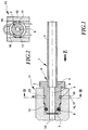
- Fig. 2
- eine Schnittansicht der Rohrleitung aus dem Stand der Technik entlang der Linie II-II aus Fig. 1;
- Fig. 3
- die erfindungsgemäße Rohrleitung in einer Schnittansicht.
- Fig. 1
- a pipeline from the prior art in a sectional view;
- Fig. 2
- a sectional view of the pipeline from the prior art along the line II-II of Fig. 1;
- Fig. 3
- the pipeline according to the invention in a sectional view.
Die Rohrleitung 1 aus dem Stand der Technik besteht aus einem Rohr 2 aus
Stahl und einem ebenfalls durch spanabhebende Verfahren aus Stahl hergestellten
Stecker 3. Das Rohr 2 und der Stecker 3 sind an der Lötstelle 4 miteinander
verlötet.The pipeline 1 from the prior art consists of a
Der Stecker 3 weist dazu eine Vertiefung 5 auf, deren Innendurchmesser im wesentlichen
dem Außendurchmesser des Rohres 2 entspricht und in die das Rohr
2 teilweise eingesteckt ist, wie dies aus Fig. 1 hervorgeht. Im Stecker 3 befindet
sich eine Durchgangsbohrung 6, die in das Rohr 2 mündet.For this purpose, the
Der Stecker 3 weist eine Dichtungsnut 7 auf, die am Umfang des Steckers 3
verläuft und einen O-Ring 8 aufnimmt. Darüber hinaus weist der Stecker 3 eine
am Umfang verlaufende Sicherungsnut 9 auf, die eine Stützfläche 10 aufweist.
Die Stützfläche 10 ist dabei die Wandung der Sicherungsnute 9.The
In der Darstellung aus Fig. 1 ist die Rohrleitung mit einem teilweise schematisch
dargestelltem Rohrleitungsanschluß 11 in einem in dieser Einsteckrichtung E
eingesteckten Zustand dargestellt. Der Rohrleitungsanschluß 11 weist ein Gehäuse
12 mit einer Aufnahme 13 auf, in die der Stecker in Einsteckrichtung E
einsteckbar ist. Das Gehäuse 12 weist eine Durchgangsbohrung 14 auf, die in
die Durchgangsbohrung 6 mündet, bzw. mit dieser fluchtet. In the illustration from FIG. 1, the pipeline is partially
Am Gehäuse 12 sind zwei als Einsteckschlitze ausgebildete Öffnungen 15 vorgesehen,
in die ein Sicherungselement senkrecht zur Längserstreckung der
Rohrleitung einsteckbar ist. Das Sicherungselement ist als Sicherungsklammer
16 ausgebildet, die federelastisch ist und zwei gebogene Arme 17 aufweist, die
die Sicherungsnut 9 umschließen Die Sicherungsklammer 16 ist durch die Öffnungen
15 aus dem Gehäuse 12 herausnehmbar oder in dieses einsteckbar. Im
eingesteckten Zustand der Sicherungsklammer ist der Stecker 3 in Axialrichtung
der Rohrleitung im Gehäuse festgelegt.Two
Die erfindungsgemäße Rohrleitung wird nun im Unterschied zur Rohrleitung aus dem Stand der Technik näher erläutert. Gleiche Bauteile sind dabei mit gleichen Bezugszeichen bezeichnet.The pipeline according to the invention is now different from the pipeline the state of the art explained in more detail. The same components are the same Reference numerals.
In Fig. 3 ist die Rohrleitung ebenfalls in einem im Rohrleitungsanschluß 11 eingesteckten
Zustand abgebildet. Im Unterschied zur Rohrleitung aus dem Stand
der Technik ist der Stecker 3 jedoch in axialer Richtung verschieblich auf dem
Rohr 2 gelagert.In Fig. 3, the pipe is also inserted into a
Das Rohr 2 besteht ebenfalls aus Stahl und ist mit zwei Bördeln 18 und 19 versehen.
Zwischen den Bördeln ist der O-Ring 8 nicht mehr in einer Dichtungsnut
7 des Steckers 3 angeordnet, sondern unmittelbar auf dem Rohr 2 selbst und
dichtet dadurch zwischen der Aufnahme 13 des Gehäuses 12 und dem Rohr 2
ab.The
Die Aufnahme 13 ist so bemessen, daß die Rohrleitung einsteckbar ist und nach
dem Einstecken nurmehr ein sehr geringes Spiel in Einsteckrichtung besteht.The
Der Stecker 3 ist nicht mehr aus Stahl gefertigt, sondern aus Kunststoff und
weist eine Sicherungsnut 9 mit Stützfläche 10 auf. Analog zur Rohrleitung aus
dem Stand der Technik weist auch hier das Gehäuse 12 zwei Öffnungen 15 auf,
in die eine Sicherungsklammer 16 eingesteckt ist, die in die Sicherungsnut 9
eingreift und dadurch den Stecker in axialer Richtung sichert. Die Sicherung erfolgt
dabei formschlüssig zwischen Gehäuse 12 und Stecker 3. Durch die Stützfläche
10 ist die Rohrleitung mit Stecker 3 entgegen der Einsteckrichtung E festgelegt,
da sich die Stützfläche 10 an der Sicherungsklammer 16 abstützt. Der
Stecker 3 nimmt in seiner Durchgangsbohrung 6 das Rohr 2 auf. Der Bördel 18,
der zwischen O-Ring und Stecker 3 angeordnet ist, bildet einen Stützring, an
dem sich das Rohr 2 entgegen der Einsteckrichtung E am Stecker 3 abstützt.The
Der Stecker 3 weist darüber hinaus noch einen Führungsabschnitt 20 auf, dessen
Außendurchmesser im wesentlichen dem Innendurchmesser der Aufnahme
13 entspricht. Dadurch erfolgt eine radiale Führung der Rohrleitung.The
Im nicht eingesteckten Zustand der Rohrleitung ist der Außendurchmesser des
O-Ringes 8 größer als der Außendurchmesser der Bördel 18 und 19.When the pipeline is not inserted, the outside diameter of the
O-
Die Rohrleitung 1 mit dem Stecker 3 bildet zusammen mit dem Rohrleitungsanschluß
11 eine Kupplung 21. Im vorliegenden Ausführungsbeispiel handelt es
sich bei der Rohrleitung 1 um eine Hydraulikrohrleitung und bei dem Rohrleitungsanschluß
11 um einen Hydraulikanschluß von z.B. einem Hydraulikzylinder
oder dergleichen. Bei dem Rohr 2 muß es sich nicht um ein völlig starres Rohr
handeln, Es kann auch ein flexibles Rohr verwendet werden. Ebenso kann das
Rohr im Bereich des Steckers fest sein und an einen Schlauch oder dergleichen
angeschlossen sein. Auch läßt sich die erfindungsgemäße Kupplung nicht nur
zum Verbinden einer Rohrleitung mit einem Rohrleitungsanschluß verwenden,
sondern auch um z.B. zwei Rohrleitungen miteinander zu verbinden. Dann kann
das Anschlußstück der einen Rohrleitung mit einer Aufnahme 13 versehen sein
ähnlich dem Gehäuse 12 und die andere Rohrleitung wie die erfindungsgemäße
Rohrleitung ausgebildet sein. Bei Anordnung zweier einander gegenüberliegender
Aufnahmen 13 können auch zwei erfindungsgemäße Rohrleitungen miteinander
verbunden werden. The pipe 1 with the
Nachfolgend wird die Wirkung und Funktionsweise der Erfindung näher erläutert:The effect and mode of operation of the invention are explained in more detail below:
Zum Koppeln der Rohrleitung 1 mit einem Rohrleitungsanschluß 11 wird das
Rohr 2 mit dem Stecker 3 und dem zuvor zwischen den beiden Bördeln 18 und
19 angeordneten O-Ring in die Aufnahme 13 des Gehäuses 12 des Rohrleitungsanschlusses
11 in Einsteckrichtung E eingesteckt. Anschließend wird die
Sicherungsklammer 16 durch die Öffnung 15 im Gehäuse 12 senkrecht zur
Längserstreckung des Rohres 2 eingesteckt, wobei die beiden Arme 17 durch
den Grund der Sicherungsnut 9 elastisch auseinandergebogen werden, bis sie
eine Stellung analog zu der in Fig. 2 dargestellten einnehmen. Alternativ kann
die Klammer bereits in der Öffnung 15 im Gehäuse 12 eingesteckt sein, da die
Schräge am Stecker in der Lage ist, beim Einschieben des Rohres mit Stecker
die Klammer federelastisch aufzuweiten. Die Klammer rastet bei komplettem Fügen
des Steckers in der Nut ein. Aufgrund der Sicherungsnut 9 ist der Stecker 3
in axialer Richtung sowohl in Steckrichtung, als auch entgegen der Steckrichtung
E festgelegt. Aufgrund des Bördels 18 kann das Rohr 2 nicht aus dem Stecker 3
herausgezogen werden.To couple the pipe 1 with a
Durch die erfindungsgemäße Rohrleitung können bereits zuvor beschichtete
Rohre verwendet werden, die bereits mit den Bördeln 18 und 19 versehen sind.
Der Stecker 3, der aus Kunststoff gefertigt ist, kann getrennt davon hergestellt
und auf das Rohr 2 aufgesteckt werden. Auf diese Weise werden Lötvorgänge
oder dergleichen zum Verbinden von Rohr und Stecker vermieden.The pipeline according to the invention can already be coated beforehand
Pipes are used which are already provided with the
Claims (13)
Applications Claiming Priority (2)
| Application Number | Priority Date | Filing Date | Title |
|---|---|---|---|
| DE1998122753 DE19822753A1 (en) | 1998-05-20 | 1998-05-20 | Pipeline |
| DE19822753 | 1998-05-20 |
Publications (2)
| Publication Number | Publication Date |
|---|---|
| EP0959291A2 true EP0959291A2 (en) | 1999-11-24 |
| EP0959291A3 EP0959291A3 (en) | 1999-12-15 |
Family
ID=7868488
Family Applications (1)
| Application Number | Title | Priority Date | Filing Date |
|---|---|---|---|
| EP99108854A Withdrawn EP0959291A3 (en) | 1998-05-20 | 1999-05-04 | Pipe coupling |
Country Status (4)
| Country | Link |
|---|---|
| EP (1) | EP0959291A3 (en) |
| BR (1) | BR9901554A (en) |
| CA (1) | CA2272016A1 (en) |
| DE (1) | DE19822753A1 (en) |
Cited By (4)
| Publication number | Priority date | Publication date | Assignee | Title |
|---|---|---|---|---|
| EP1701082A1 (en) * | 2005-03-10 | 2006-09-13 | FTE automotive GmbH | Conduit end portion with overmoulded plug arrangement |
| FR3001024A1 (en) * | 2013-01-17 | 2014-07-18 | Delphi Automotive Systems Lux | FAST CONNECTION DEVICE. |
| CN109029622A (en) * | 2018-05-28 | 2018-12-18 | 佛山市川东磁电股份有限公司 | A kind of connection structure of urea for vehicle liquid level sensor and connector |
| CN110216920A (en) * | 2019-06-18 | 2019-09-10 | 安徽猛牛彩印包装有限公司 | A kind of dissection waste material storage high-efficient treatment device on Bag Making Machine |
Families Citing this family (4)
| Publication number | Priority date | Publication date | Assignee | Title |
|---|---|---|---|---|
| DE102004044917A1 (en) * | 2004-09-14 | 2006-03-16 | Fte Automotive Gmbh | Detachable plug connection for pipelines or the like |
| DE102005050490A1 (en) * | 2005-10-21 | 2007-04-26 | Henn Gmbh & Co. Kg | Plug connection on pipes and hoses with a pipe locking ring |
| DE102014214186A1 (en) * | 2014-07-22 | 2016-01-28 | Schaeffler Technologies AG & Co. KG | connecting device |
| DE102022114275A1 (en) | 2022-06-07 | 2023-12-07 | Valeo Powertrain Gmbh | Sensor and sensor assembly |
Family Cites Families (4)
| Publication number | Priority date | Publication date | Assignee | Title |
|---|---|---|---|---|
| DE2028712A1 (en) * | 1970-06-11 | 1971-12-16 | Kessler & Co Tech Chem Gmbh | Detachable pipe or hose coupling |
| DE3531926A1 (en) * | 1985-09-07 | 1987-03-19 | Kugelfischer G Schaefer & Co | DETACHABLE CONNECTOR |
| US4874174A (en) * | 1987-03-05 | 1989-10-17 | Aisin Seiki Kabushiki Kaisha | Tube connecting unit |
| US5275448A (en) * | 1991-09-10 | 1994-01-04 | Huron Products Industries, Inc. | Quick connect tubing connector and method of assembly |
-
1998
- 1998-05-20 DE DE1998122753 patent/DE19822753A1/en not_active Ceased
-
1999
- 1999-05-04 EP EP99108854A patent/EP0959291A3/en not_active Withdrawn
- 1999-05-17 CA CA 2272016 patent/CA2272016A1/en not_active Abandoned
- 1999-05-19 BR BR9901554A patent/BR9901554A/en not_active Application Discontinuation
Non-Patent Citations (1)
| Title |
|---|
| None |
Cited By (6)
| Publication number | Priority date | Publication date | Assignee | Title |
|---|---|---|---|---|
| EP1701082A1 (en) * | 2005-03-10 | 2006-09-13 | FTE automotive GmbH | Conduit end portion with overmoulded plug arrangement |
| FR3001024A1 (en) * | 2013-01-17 | 2014-07-18 | Delphi Automotive Systems Lux | FAST CONNECTION DEVICE. |
| WO2014111214A1 (en) * | 2013-01-17 | 2014-07-24 | Delphi Automotive Systems Luxembourg Sa | Quick connector device |
| US10502347B2 (en) | 2013-01-17 | 2019-12-10 | Mahle International Gmbh | Quick connector device |
| CN109029622A (en) * | 2018-05-28 | 2018-12-18 | 佛山市川东磁电股份有限公司 | A kind of connection structure of urea for vehicle liquid level sensor and connector |
| CN110216920A (en) * | 2019-06-18 | 2019-09-10 | 安徽猛牛彩印包装有限公司 | A kind of dissection waste material storage high-efficient treatment device on Bag Making Machine |
Also Published As
| Publication number | Publication date |
|---|---|
| EP0959291A3 (en) | 1999-12-15 |
| DE19822753A1 (en) | 1999-12-02 |
| CA2272016A1 (en) | 1999-11-20 |
| BR9901554A (en) | 2000-02-22 |
Similar Documents
| Publication | Publication Date | Title |
|---|---|---|
| DE2832614C2 (en) | Connection piece for pipelines | |
| EP0743479B1 (en) | Arrangement for connecting a metal pipe to a receiving sleeve | |
| DE2921568A1 (en) | PLUG-IN CONNECTOR FOR COMPRESSED AIR BRAKE SYSTEM | |
| AT410706B (en) | CONNECTING DEVICE FOR A PLASTIC PIPE | |
| EP0615089A1 (en) | Separable plug-in connection for high pressure conduits | |
| DE29921406U1 (en) | Plug-in fitting for quick and detachable connection of pressure medium lines | |
| DE19614684A1 (en) | Coupler for pipes, branches and tubular fittings parts for water fitting | |
| EP1673185B1 (en) | Method and device for creating a press-fitted pipe joint with a plug-type connection | |
| EP0959291A2 (en) | Pipe coupling | |
| DE3923579A1 (en) | Connector for plastics pipes - is in one piece with widening bore socket for holding ring and sealing ring | |
| DE3713200A1 (en) | CONNECTOR | |
| DE4117932C2 (en) | ||
| CH581273A5 (en) | Snap connection between hose ends - has inner and outer sleeves with O-ring seal and finger with ridge and groove | |
| DE2002826A1 (en) | Coupling piece for pipes or hoses | |
| DE19927591B4 (en) | Device for sealingly connecting a sewer pipe to a connecting pipe | |
| DE8610238U1 (en) | Hose plug-in coupling for electrical protective hose screw connections | |
| DE102005044751A1 (en) | Pipe connecting system comprises socket, into which plug-in connector fits, which is made up of outer sleeve and inner sleeve with claws which are compressed to hold plug-in connector when it is rotated inside outer sleeve | |
| DE102007049996A1 (en) | pipe connection | |
| DE10130003A1 (en) | Pipe connection system for joining plastic pipes comprises a sleeve which is a preproduced compound item consisting of a plastic lining and a metal reinforcing ring | |
| DE10031729C2 (en) | Plug connection between a ring-corrugated hose and a smooth tube | |
| DE2600621C3 (en) | Threadless connection for pipes and processes for their manufacture | |
| DE2752761C2 (en) | Method for producing a quick coupling | |
| DE10113354B4 (en) | Repair part for corrugated pipes | |
| DE20003980U1 (en) | Connection clamp for chimney pipe elements with socket ends and push-in ends for socket connectors | |
| CH686798A5 (en) | Injection-moulded connecting sleeve between pipes |
Legal Events
| Date | Code | Title | Description |
|---|---|---|---|
| PUAI | Public reference made under article 153(3) epc to a published international application that has entered the european phase |
Free format text: ORIGINAL CODE: 0009012 |
|
| PUAL | Search report despatched |
Free format text: ORIGINAL CODE: 0009013 |
|
| AK | Designated contracting states |
Kind code of ref document: A2 Designated state(s): DE ES FR GB IT |
|
| AX | Request for extension of the european patent |
Free format text: AL;LT;LV;MK;RO;SI |
|
| AK | Designated contracting states |
Kind code of ref document: A3 Designated state(s): AT BE CH CY DE DK ES FI FR GB GR IE IT LI LU MC NL PT SE |
|
| AX | Request for extension of the european patent |
Free format text: AL;LT;LV;MK;RO;SI |
|
| 17P | Request for examination filed |
Effective date: 20000605 |
|
| AKX | Designation fees paid |
Free format text: DE ES FR GB IT |
|
| STAA | Information on the status of an ep patent application or granted ep patent |
Free format text: STATUS: THE APPLICATION HAS BEEN WITHDRAWN |
|
| 18W | Application withdrawn |
Withdrawal date: 20001009 |