EP0958022B1 - Apparatus for separation - Google Patents
Apparatus for separation Download PDFInfo
- Publication number
- EP0958022B1 EP0958022B1 EP97944271A EP97944271A EP0958022B1 EP 0958022 B1 EP0958022 B1 EP 0958022B1 EP 97944271 A EP97944271 A EP 97944271A EP 97944271 A EP97944271 A EP 97944271A EP 0958022 B1 EP0958022 B1 EP 0958022B1
- Authority
- EP
- European Patent Office
- Prior art keywords
- screening device
- screening
- helix
- bodies
- liquid
- Prior art date
- Legal status (The legal status is an assumption and is not a legal conclusion. Google has not performed a legal analysis and makes no representation as to the accuracy of the status listed.)
- Expired - Lifetime
Links
- 238000000926 separation method Methods 0.000 title description 6
- 238000012216 screening Methods 0.000 claims abstract description 163
- 239000007788 liquid Substances 0.000 claims abstract description 70
- 239000007787 solid Substances 0.000 claims description 29
- 239000002245 particle Substances 0.000 claims description 16
- XLYOFNOQVPJJNP-UHFFFAOYSA-N water Substances O XLYOFNOQVPJJNP-UHFFFAOYSA-N 0.000 claims description 5
- 238000006073 displacement reaction Methods 0.000 claims description 3
- 239000000463 material Substances 0.000 abstract description 13
- 230000006835 compression Effects 0.000 description 14
- 238000007906 compression Methods 0.000 description 14
- 239000000126 substance Substances 0.000 description 9
- 238000010276 construction Methods 0.000 description 8
- 239000012535 impurity Substances 0.000 description 8
- 239000012530 fluid Substances 0.000 description 5
- 238000000034 method Methods 0.000 description 4
- 238000004140 cleaning Methods 0.000 description 3
- 230000000694 effects Effects 0.000 description 3
- 238000011144 upstream manufacturing Methods 0.000 description 3
- 238000009825 accumulation Methods 0.000 description 2
- 238000010420 art technique Methods 0.000 description 2
- 230000008901 benefit Effects 0.000 description 2
- 230000005484 gravity Effects 0.000 description 2
- 230000008569 process Effects 0.000 description 2
- 230000009467 reduction Effects 0.000 description 2
- 230000004044 response Effects 0.000 description 2
- 238000004062 sedimentation Methods 0.000 description 2
- 238000003307 slaughter Methods 0.000 description 2
- 239000007921 spray Substances 0.000 description 2
- 230000009471 action Effects 0.000 description 1
- 238000002485 combustion reaction Methods 0.000 description 1
- 150000001875 compounds Chemical class 0.000 description 1
- 239000012141 concentrate Substances 0.000 description 1
- 230000001276 controlling effect Effects 0.000 description 1
- 230000001419 dependent effect Effects 0.000 description 1
- 230000008021 deposition Effects 0.000 description 1
- 238000010438 heat treatment Methods 0.000 description 1
- 230000008676 import Effects 0.000 description 1
- 239000010841 municipal wastewater Substances 0.000 description 1
- 230000008092 positive effect Effects 0.000 description 1
- 230000001105 regulatory effect Effects 0.000 description 1
- 239000013049 sediment Substances 0.000 description 1
- 238000005507 spraying Methods 0.000 description 1
Images
Classifications
-
- E—FIXED CONSTRUCTIONS
- E03—WATER SUPPLY; SEWERAGE
- E03F—SEWERS; CESSPOOLS
- E03F5/00—Sewerage structures
- E03F5/14—Devices for separating liquid or solid substances from sewage, e.g. sand or sludge traps, rakes or grates
-
- B—PERFORMING OPERATIONS; TRANSPORTING
- B01—PHYSICAL OR CHEMICAL PROCESSES OR APPARATUS IN GENERAL
- B01D—SEPARATION
- B01D21/00—Separation of suspended solid particles from liquids by sedimentation
- B01D21/0003—Making of sedimentation devices, structural details thereof, e.g. prefabricated parts
-
- B—PERFORMING OPERATIONS; TRANSPORTING
- B01—PHYSICAL OR CHEMICAL PROCESSES OR APPARATUS IN GENERAL
- B01D—SEPARATION
- B01D21/00—Separation of suspended solid particles from liquids by sedimentation
- B01D21/0012—Settling tanks making use of filters, e.g. by floating layers of particulate material
-
- B—PERFORMING OPERATIONS; TRANSPORTING
- B01—PHYSICAL OR CHEMICAL PROCESSES OR APPARATUS IN GENERAL
- B01D—SEPARATION
- B01D21/00—Separation of suspended solid particles from liquids by sedimentation
- B01D21/0039—Settling tanks provided with contact surfaces, e.g. baffles, particles
-
- B—PERFORMING OPERATIONS; TRANSPORTING
- B01—PHYSICAL OR CHEMICAL PROCESSES OR APPARATUS IN GENERAL
- B01D—SEPARATION
- B01D21/00—Separation of suspended solid particles from liquids by sedimentation
- B01D21/02—Settling tanks with single outlets for the separated liquid
-
- B—PERFORMING OPERATIONS; TRANSPORTING
- B01—PHYSICAL OR CHEMICAL PROCESSES OR APPARATUS IN GENERAL
- B01D—SEPARATION
- B01D21/00—Separation of suspended solid particles from liquids by sedimentation
- B01D21/18—Construction of the scrapers or the driving mechanisms for settling tanks
- B01D21/183—Construction of the scrapers or the driving mechanisms for settling tanks with multiple scraping mechanisms
-
- B—PERFORMING OPERATIONS; TRANSPORTING
- B01—PHYSICAL OR CHEMICAL PROCESSES OR APPARATUS IN GENERAL
- B01D—SEPARATION
- B01D21/00—Separation of suspended solid particles from liquids by sedimentation
- B01D21/18—Construction of the scrapers or the driving mechanisms for settling tanks
- B01D21/20—Driving mechanisms
-
- B—PERFORMING OPERATIONS; TRANSPORTING
- B01—PHYSICAL OR CHEMICAL PROCESSES OR APPARATUS IN GENERAL
- B01D—SEPARATION
- B01D21/00—Separation of suspended solid particles from liquids by sedimentation
- B01D21/24—Feed or discharge mechanisms for settling tanks
- B01D21/2444—Discharge mechanisms for the classified liquid
-
- B—PERFORMING OPERATIONS; TRANSPORTING
- B01—PHYSICAL OR CHEMICAL PROCESSES OR APPARATUS IN GENERAL
- B01D—SEPARATION
- B01D21/00—Separation of suspended solid particles from liquids by sedimentation
- B01D21/24—Feed or discharge mechanisms for settling tanks
- B01D21/245—Discharge mechanisms for the sediments
- B01D21/2461—Positive-displacement pumps; Screw feeders; Trough conveyors
-
- B—PERFORMING OPERATIONS; TRANSPORTING
- B03—SEPARATION OF SOLID MATERIALS USING LIQUIDS OR USING PNEUMATIC TABLES OR JIGS; MAGNETIC OR ELECTROSTATIC SEPARATION OF SOLID MATERIALS FROM SOLID MATERIALS OR FLUIDS; SEPARATION BY HIGH-VOLTAGE ELECTRIC FIELDS
- B03B—SEPARATING SOLID MATERIALS USING LIQUIDS OR USING PNEUMATIC TABLES OR JIGS
- B03B5/00—Washing granular, powdered or lumpy materials; Wet separating
- B03B5/48—Washing granular, powdered or lumpy materials; Wet separating by mechanical classifiers
- B03B5/52—Spiral classifiers
-
- B—PERFORMING OPERATIONS; TRANSPORTING
- B07—SEPARATING SOLIDS FROM SOLIDS; SORTING
- B07B—SEPARATING SOLIDS FROM SOLIDS BY SIEVING, SCREENING, SIFTING OR BY USING GAS CURRENTS; SEPARATING BY OTHER DRY METHODS APPLICABLE TO BULK MATERIAL, e.g. LOOSE ARTICLES FIT TO BE HANDLED LIKE BULK MATERIAL
- B07B1/00—Sieving, screening, sifting, or sorting solid materials using networks, gratings, grids, or the like
- B07B1/18—Drum screens
- B07B1/22—Revolving drums
- B07B1/24—Revolving drums with fixed or moving interior agitators
-
- B—PERFORMING OPERATIONS; TRANSPORTING
- B01—PHYSICAL OR CHEMICAL PROCESSES OR APPARATUS IN GENERAL
- B01D—SEPARATION
- B01D2221/00—Applications of separation devices
- B01D2221/06—Separation devices for industrial food processing or agriculture
Definitions
- the present invention relates to an apparatus for separation and displacement of bodies, particles and/or similar impurities from a liquid according to the preamble of claim 1.
- bodies, particles and/or similar impurities is used in this description to signify all material which, when it is located in a liquid, comes to rest against a separation apparatus, or device for example a grid or a screen through which the liquid passes.
- solid substances also occurs but will be employed in this description generally exclusively for a screenings process in which a liquid content has been reduced.
- screenings be freed of soluble, for example biological compounds included in the screenings. This applies particularly to screenings sent to landfill deposition.
- the conveyor screw is disposed in a path which, in its lower region, forms a part-cylindrical screen surface. Above the water surface, the path is designed as a tube or casing surrounding the conveyor screw. In its upper end, the casing is provided with a discharge aperture. In the region ahead of the discharge aperture, the threads of the conveyor screw are of reducing pitch, whereby a certain compression and dewatering take place of the matter or bodies being upwardly transported. However, capacity in these apparatuses is extremely low.
- Apparatuses of the above described type are employed for mechanical treatment under restricted flow conditions of municipal waste water, treatment plants for purifying (screening) polluted liquids, for example water within industries, such as paper mills, food industries and slaughter houses.
- a serious drawback in the prior art technique is that the diameter of the conveyor helix is determined based upon estimated maximum liquid flow for which the apparatus is to be dimensioned, since the diameter of the conveyor helix is determined by the radius of curvature of the screen surface.
- large liquid flows require larger diameters of the conveyor helix, which entails unwieldy and expensive designs and constructions.
- the average degree of efficiency in prior art apparatuses is low. This circumstance is the immediate reason why apparatuses of the type described here have only come into use in relatively limited maximum flows, seldom above 100-125 1/s.
- European patent publication EP-A2-0 640 370 describes an apparatus with two cooperating screening devices, which implies that the above-described drawbacks are partly obviated.
- the apparatus described suffers from the drawback that an increased screen surface is, in its effective extent, restricted unless the construction is made extremely space-demanding and expensive. The reason is that they are oriented parallel with a used inclining screen/upward conveyance apparatus.
- the increased screen surface also requires that the supply channel be expanded in the area of the screen surface.
- the patent publication more precisely describes an apparatus whereby it will be possible to extract solid particles mixed with a fluid passing a channel (1).
- a transport path (4) in the form of a transport means (3) with a driven transporting helix formed as a conveyer (6).
- the transporting means (3) is formed at its one end section with a solid particles extracting outlet (9) and at its opposite end section there is arranged a semi-cylindrical screen surface (15), where low arranged solid particles may be extracted from the fluid and transported upwards through the outlet (9).
- the transporting means (3), between the outlet (9) and the screening surface (15), is related to a further or second screening arrangement (19).
- This screening surface or arrangement (19) is oriented adjacent to the transporting means (3) and is formed as an extension of the screening or first screening arrangement (15) opposite the transporting device (3).
- the second screening arrangement (19) is formed as a circular disc and perforated and only a small portion of that screen is effective for separation of solid particles during high flow conditions.
- the level of fluid must reach up to said perforated disc before this arrangement starts to be effective and at the most about 50% of the disc is used for separation purposes only.
- the screen surface (15) is dimensioned so that the surface projected onto the transporting means (3) is larger than the diameter of the transport path (4) and the second screening arrangement (19) is arranged adjacent to the top level (20) of the fluid in the channel (1).
- the only demonstrated method of attempting to control the degree of compression and thereby the dewatering efficiency is to vary the length of the "unthreaded" compression space, ahaead of the discharge opening, i.e. to increase or reduce the length of a "friction plug" which is formed by the conveyed matter or solid substance.
- the difficulty in attempting, in this manner, to control the degree of dewatering is obvious, since, in practice, the quantity of screenings per unit of time varies dramatically (the matters or bodies "drie” more or less when remaining for varying periods of time during which it is subjected to compression).
- the present invention relates to an apparatus in which the above-outlined drawbacks have been obviated. This is attained by means of the apparatus according to the characterizing clause of claim 1.
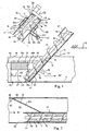
- the Figures illustrate embodiment 6 of an apparatus for removing bodies and/or particles from a flowing liquid 60.
- the apparatus includes a lower portion 10 including a first screening device 40 and an upper portion 11 including a discharge portion 11a.
- the apparatus also includes an intermediate portion 12, which forms a conveyor device 12' between the lower portion 10 and the upper portion 11.
- a conveyor helix 3 is disposed in a path 7 which is formed by said lower portion 10, said upper portion 11 and the intermediate portion 12 (in those embodiments in which the intermediate portion is included).
- Drive means are disposed at the upper region of the apparatus.
- the first screening device 40, the intermediate portion 12 and the upper portion 11 form a screen and conveyor device which separates bodies and/or particles from said liquid 60 and displaces the screenings or solid substances formed by separation to the upper region of the apparatus.
- the conveyor helix consists of a helical thread blade 33.
- thread blade has here been employed without any restrictive import and comprises a helical body, whose cross section is, for example, rectangular, conical, trapezoidal, ziggurat-shaped defining surfaces, etc.
- the term thread blade may also be taken to refer to a screw arrangement which is composed of two or more mutually interconnected part helices.
- the helical thread blade is designated hereinafter generally as a "helix" 33.
- the prime mover 30 is disposed to rotate the helix 33 about its geometric centre axis 32.
- the path 7 and the geometric centre axis 32 of the helix make an angle " ⁇ " with the horizontal plane 5.
- the intermediate portion 12 and the upper portion 11 are designed with a casing 17 which surrounds the helix 3.
- the first casing 17 is of substantially cylindrical design. In both portions, the casing has a cross section which generally includes at least one corner. In the region of a discharge device the casing is generally provided with a substantially circular cross section.
- the first screening device 40 comprises a first portion 41 located beneath a calculated highest liquid level 6a of the liquid which is fed to the inlet portion of said screening device, 40 and a second portion 42 located above said calculated highest liquid level 6a.
- the wall section 17a of the first screening device 40 forms a screen surface, which is provided with passages 15 for liquids.
- the dimensions of the passages 15 are adapted to the size of those bodies, particles and/or similar impurities 61 which are to be separated from liquid 60' passing through said screening device 40.
- the cross section of that portion of the path 7 which the screening device 40 forms and the outer radius of the helix are adapted to one another such that, in those portions of the screening device 40 where the helix abuts against the wall 17a of the screen device 40, this forms a curved surface with a radius of curvature which, in the circumferential direction, substantially coincides with or exceeds the outer radius of the helix.
- a displaceable casing half 17b is disposed in the region of the second portion 42.
- the casing half generally has a cross section which corresponds to the cross section of the upper half of the first casing 17 in the intermediate portion 12 of the first apparatus.
- the casing half 17b may be in cooperation with the wall 17a of the screening device 40 substantially surrounds the helix 3 in the lower portion 10 or 41 of the apparatus.
- control devices are normally included which only permit one row of nozzles (not shown) to emit liquid jets, namely that row whose nozzles, in the relevant direction of rotation, direct their liquid jets towards the drive side of the first screening device 40.
- drive side is here taken to signify that area of the first screening device along which the major portion of the conveyed matters or bodies are displaced on rotation of the helix.
- Figs. 1 and 2 show an embodiment in which the apparatus includes an extra screening apparatus or device 70, a second screening device, provided with passages 15a for liquid, this device being hereafter generally referred to as a second screening or device 70 which is disposed beside the first screening device 40.
- Fig. 2 which shows the apparatus from above the first screening device 40 is placed adjacent to one side wall 65 of a channel 62.
- the second screening device 70 is disposed between a second side wall 66 of the channel 62 and the first screening device 40.
- the second screening device 70 makes an obtuse angle ⁇ with an upstream section of the channel wall 66.
- transverse wall section 67 which is impenetrable for liquid.
- the second screening device 70 connects to an upper edge 69 of the transverse wall.
- a scraper device (not shown in the Figures) is provided for displacing bodies which have accumulated against the second screening device and the portion 68b towards the first screening device 40.
- a vertical wall section 68 connects the second screening portion 70 with the first screening device 40.
- the lower portion 68a of the wall flush with the edge 69 is impenetrable for liquid, while its upper portion 68b is, designed as said second screening device 70.
- the second screening device 70 is, as a rule, placed a distance from the bottom 64 of the channel. This distance is determined by a calculated size of normal flow through the channel 62 and is selected such that liquid passes through the second screening portion 68b only when the flow in the channel 62 exceeds a predetermined flow or level. There will hereby be achieved the positive effect that, on flow which is less than the predetermined flow, all liquid passes through the screening device 40. This is a factor which entails that the desired size of the flow, and thereby the desired minimum flow rate will be maintained through the screening device 40 even in the event of slight or small flow volumes. An increased flow prevents sedimentation ahead of the screening device.
- the second screening device 70 with a wall 67, as well as said second screening portion 68b (70) with the wall portion 68a are, as a rule, of vertical extent in the liquid 60.
- the angle of inclination of the first screening device 40 is, as a rule, 30-50 ° to the horizontal plane.
- the width of the first screening device 40 open to the liquid flow is preferably approx. 30-50 cm and the majority of channels in treatment plants throughout the world seldom display widths exceeding 2.5 m. The majority of widths is less than 1.2 m.
- the first screening device 40 and the second screening device 70 together cover the entire width of the channel 62 and together offer an optimum screening surface for the onward flowing liquid.
- the angle ⁇ may be permitted to vary without operation being jeopardized or without the design and construction being appreciably more expensive.
- the present invention affords the possibility of simple dimensioning of the exposed screening surface in view of liquid flow and demands on the size of the screen aperture, at the same time as the first screening device 40, the intermediate portion 12 and the upper portion 11 are permitted to be dimensioned according to calculated maximum quantity of screenings which need to be handled per unit of time.
- a screening device is placed between the side walls 65,66 of the channel, on extra screening portions 68b being provided between the first screening device 40 and the side walls 65,66 of the channel on both sides of said screening device 40.
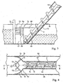
- Figs. 3 and 4 show yet a further embodiment of the present invention in which a second screening portions or devices 74 are provided between the first screening device 40 and the walls of the channel on both sides of said screening device 40.
- the second screening devices 71, 71' are placed vertically in a manner corresponding to that previously disclosed for the embodiment according to Figs. 1 and 2.
- the screening portions or devices 71,71' are vertically oriented and having a cross section which constitutes a portion of a circle periphery.
- the screening devices 71, 71' thus form partly cylindrical screening surfaces 75 75'.
- a scraper device 71 is disposed on an arm 72 rotatably about a vertical shaft 73. While this embodiment is shown with two second screening devices 71, 71', it will be ovious to a person skilled in the art that, in other embodiments, only one second screening device is included which is placed corresponding to that shown in Fig. 1 or 2.
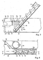
- Figs. 5 and 6 show still a further embodiment of the second screening device 70'.
- Fig. 6 which shows the second screening device from above, this is disposed between a second side wall 66 of the channel, and a first screening device 40 which is placed adjacent to an opposed side wall 65.
- the second screening device 70' includes a cylinder rotary about its centre axis and whose circumferential surface is provided with perforations or apertures 15a so as to form a screening surface 77 through which liquid flowing in the channel may pass.
- the centre axis of the cylinder is substantially vertically oriented.
- the cylinder 70 is disposed to rotate in such a direction that material entrapped on its front side (the side facing towards the liquid flow) is displaced on rotation of the cylinder substantially horizontally in a direction towards the inclining first screening device 40.
- a scraper device 76 oriented in the axial direction of the cylinder 70'. is disposed adjacent the circumferential surface of the cylinder and is placed such that material scraped off falls down upstream or towards the screening surface which is formed by the wall 17a of the first screening device 40.
- a "box" 79 which is impenetrable for liquid and whose upper surface 69 is in conjunction with the bottom periphery 78 of the rotating cylinder 70.
- the box 79 has, as a rule, a wall 68a which faces counter-currently and which corresponds to the above described lower portion of the vertical wall 68 which is impenetrable for liquid.
- the wall 68a of the box is of an orientation which entails that there is formed, between the wall 66 of the channel and the wall of the box, an obtuse angle corresponding to the angle ⁇ previoiusly defined in this description.
- the design of the box entails that, in a manner corresponding to that disclosed above, there is formed upstream of the first screening device a flow path tapering towards the first screening device 40 for the flowing liquid. This design of the box entails the advantage that the flow rate is maintained even in small flow volumes and that the risk of sedimentation is reduced during those periods when the liquid flows are slight.
- the design with the rotary screening cylinder in accordance with the foregoing entails that liquid passes through the circumferential surface of the cylinder in both directions, i.e. also from inside and out, which gives the possibility of auto-cleaning-of the apertures 15a in the circumferential surface.
- Extra cleaning of the apertures of the cylinder when they are located on that side of the cylinder which is downstream, is provided in certain embodiments by means of vertically fixed nozzles 43 which spray liquid against the inside of the circumferential surface of the cylinder.
- cleaning devices not shown in the Figures
- such as brushes or scrapers remove residual matter from the outside of the cylinder when its circumferential surface passes the cleaning devices.
- the incling first screening device 40 is placed centrally in the channel with one second screening cylinder 70 on both sides of said first screening device, the screening cylinders forming said second screening portions in the apparatus.
- the purpose of the casing is to ensure efficient inward transport of screenings floating on the liquid surface and, at the same time, to render the upward transport operation more efficient.
- the plug Even when the hatch has been opened and the helix exercises pressure on the plug, the plug will generally remain substantially intact in its end located most proximal the helix, while matter in the opposite end of the plug will be broken loose from the plug in connection with the discharge through the discharge aperture 14 .
- the degree of compression determines the size of the reduction of the liquid content of the matters or bodies, and thereby the total solids of the material passing through the discharge opening 14.
- the degree of compression is controlled by the force which is required to open the hatch.
- the apparatus is provided with control means for adjusting the requisite force.
- the increasing compression of the screenings entails that a steadily increasing torque is required to rotate the helix 3 fixedly connected to the drive shaft 18 and the discharge device 51.
- An automatically operating regulation of the opening and closing of the hatch, and thereby of the liquid content of the screenings or the compression will be obtained in that the hatch of the discharge opening 14 is pretensioned, for example mechanically or pneumatically.
- the degree of compression of the material is adjusted by setting (e.g. by modifying the pretensioning of the spring) of the total force which the matter is to apply against the hatch in order for this to be opened or closed.
- the degree of compression is adjusted in that a device (e.g. a hydraulic piston, a pneumatic piston, an electro-mechanical operating device, etc.) opens or closes the hatch when the driving power for rotating the helix passes a pre-set value (as a rule the current strength is measured).
- a device e.g. a hydraulic piston, a pneumatic piston, an electro-mechanical operating device, etc.
- the total force which is required to displace the plug towards the discharge device determines the total solids of the matter which is discharged out of the apparatus.
- the degree of compression increases and thereby the total solids of the material which is discharged out of the apparatus.
- the apparatus includes an intermediate portion 12.
- this constitutes merely a conveyor portion whose length is adapted in response to the level at which the discharge of the matter out of the apparatus is to take place. Since the technical effect of the apparatus is only dependent upon the lower portion 10 of the apparatus and the upper portion 11 of the apparatus, certain embodiments lack the intermediate portion 12.
- first screening device 40 and second screening portions 70,74 makes it possible to dimension the size of the total screening surface in view of the largest and smallest liquid flow and regardless of this factor, to dimension the transport capacity of the first screening device 40, the intermediate portion 12, and the upper portion 11 in accordance with the expected quantity of screenings per unit of time.
- the size of the flow area in minimum flow will remain unchanged.
- the described embodiments with said second screening device offer efficient screening combined with horizontally directed advancement of entrapped screenings to the inclined first screening device 40.
- Figs. 1 and 2 show one embodiment in which, for example the dimensioning of the apparatus, the second screening device 70 and thereby the permitted maximum liquid flow may readily be increased by altering the angle ⁇ between the second screening device and the wall or walls 65,66 of the channel.
- the reduced flow areas of the screening surfaces is compensated for by an increase of the obtuse angle ⁇ between the second screening device 70 and the channel walls 65,66.
- problems often occur in the accumulation of sedimented matter ahead of the screen grid in channels at, for example, water treatment plants .
- the accumulation is because the channels are dimensioned to handle flows of greatly varying sizes.
- the channels are dimensioned to permit large maximum flows, at the same time as, during long periods of time, the flows may be very small. In the event of very small flows, the flow rate is extremely low, for which reason matters or bodies sediment ahead of the screen grid of the channels.
- the problem inherent in sedimented matter is eliminated in that the flow rate ahead of the grid is maintained even in the event of small flows in the channel, because the tight wall portion 67 beneath the second screening surface 70 concentrates the flow such that liquid only passes through the passages 15 the first screening device 40.
Landscapes
- Chemical Kinetics & Catalysis (AREA)
- Chemical & Material Sciences (AREA)
- Health & Medical Sciences (AREA)
- Life Sciences & Earth Sciences (AREA)
- Engineering & Computer Science (AREA)
- Hydrology & Water Resources (AREA)
- Public Health (AREA)
- Water Supply & Treatment (AREA)
- Separation Of Solids By Using Liquids Or Pneumatic Power (AREA)
- Combined Means For Separation Of Solids (AREA)
- Sewage (AREA)
- Screw Conveyors (AREA)
- Sampling And Sample Adjustment (AREA)
- Investigating Or Analysing Biological Materials (AREA)
- Treatment Of Fiber Materials (AREA)
- Electrical Discharge Machining, Electrochemical Machining, And Combined Machining (AREA)
- Filtration Of Liquid (AREA)
- Centrifugal Separators (AREA)
Applications Claiming Priority (3)
| Application Number | Priority Date | Filing Date | Title |
|---|---|---|---|
| SE9603689 | 1996-10-07 | ||
| SE9603689A SE507499C2 (sv) | 1996-10-07 | 1996-10-07 | Separationsanordning försedd med transportspiral och silorgan |
| PCT/SE1997/001681 WO1998015335A1 (en) | 1996-10-07 | 1997-10-07 | Apparatus for separation |
Publications (2)
| Publication Number | Publication Date |
|---|---|
| EP0958022A1 EP0958022A1 (en) | 1999-11-24 |
| EP0958022B1 true EP0958022B1 (en) | 2006-04-26 |
Family
ID=20404185
Family Applications (1)
| Application Number | Title | Priority Date | Filing Date |
|---|---|---|---|
| EP97944271A Expired - Lifetime EP0958022B1 (en) | 1996-10-07 | 1997-10-07 | Apparatus for separation |
Country Status (9)
| Country | Link |
|---|---|
| US (1) | US6096201A (enExample) |
| EP (1) | EP0958022B1 (enExample) |
| JP (1) | JP4117908B2 (enExample) |
| AT (1) | ATE324166T1 (enExample) |
| AU (1) | AU4580597A (enExample) |
| CA (1) | CA2268002A1 (enExample) |
| DE (1) | DE69735774T2 (enExample) |
| SE (1) | SE507499C2 (enExample) |
| WO (1) | WO1998015335A1 (enExample) |
Families Citing this family (26)
| Publication number | Priority date | Publication date | Assignee | Title |
|---|---|---|---|---|
| US6523727B2 (en) | 2000-04-26 | 2003-02-25 | Peerless Machinery Corp. | Dough feeding unit |
| SE0003698D0 (sv) * | 2000-05-09 | 2000-10-13 | Dunbriar Invest Ltd | Avskiljningsanordning med separationstratt |
| US6953524B2 (en) * | 2000-08-29 | 2005-10-11 | Hydro International Plc | Screen assembly for combined sewer overflow weir |
| DE10302494B3 (de) * | 2003-01-23 | 2004-09-16 | Hans Huber Ag Maschinen- Und Anlagenbau | Vorrichtung zum Entfernen von Siebgut aus in einem Gerinne strömender Flüssigkeit |
| US7073433B2 (en) * | 2003-03-11 | 2006-07-11 | Jwc Environmental | Auger dewatering system |
| DE10316173B4 (de) * | 2003-04-04 | 2006-03-16 | Hans Huber Ag Maschinen- Und Anlagenbau | Vorrichtung zum Entfernen von feinem Siebgut aus einer Flüssigkeit |
| US20080116151A1 (en) * | 2006-11-17 | 2008-05-22 | Clifford James Suthard | Methods of removing solids from liquids |
| US8449779B2 (en) * | 2009-01-09 | 2013-05-28 | Granbury Thompson Group, Llc | Backflow collection receptacle and method for reclaiming the same |
| US9597614B2 (en) | 2009-01-09 | 2017-03-21 | Granbury Thompson Group, Llc | Backflow collection system and method for reclaiming the same |
| US8470183B2 (en) | 2009-11-05 | 2013-06-25 | Daritech, Inc. | Systems and methods for extracting sand from raw slurry material |
| US8926846B2 (en) | 2009-11-05 | 2015-01-06 | Daritech, Inc. | Systems and methods for extracting particulate from raw slurry material |
| CA2764679C (en) * | 2011-01-20 | 2019-01-15 | Daritech, Inc. | Systems and methods for extracting particulate from raw slurry material |
| AT511982B1 (de) * | 2011-10-11 | 2013-10-15 | Andritz Ag Maschf | Schneckenpresse |
| CA2892505A1 (en) | 2014-05-27 | 2015-11-27 | Daritech, Inc. | Feed systems and methods for rotary screen separators |
| CA2893311A1 (en) | 2014-05-30 | 2015-11-30 | Daritech, Inc. | Cleaning systems and methods for rotary screen separators |
| US10603675B2 (en) | 2014-11-02 | 2020-03-31 | Dari-Tech, Inc. | Systems and methods for extracting particulate from raw slurry material |
| CN106719109B (zh) * | 2017-01-11 | 2023-04-25 | 江西农业大学 | 一种蜂王浆自动取浆装置 |
| US10967300B2 (en) * | 2017-08-29 | 2021-04-06 | Green Flow Industries, LLC | Transportable separation and monitoring apparatus with auger |
| IT201900007305A1 (it) * | 2019-05-27 | 2020-11-27 | Aqseptence Group Carpi S R L | Dispositivo per il trasporto di solidi |
| US10968617B2 (en) * | 2019-06-04 | 2021-04-06 | Terry Duperon | Lift station maintenance device |
| CN110525896B (zh) * | 2019-08-02 | 2020-12-11 | 淮南市恒发新型建材有限公司 | 一种烧结砖原料滤式输送器 |
| US20230339690A1 (en) * | 2020-09-08 | 2023-10-26 | Alan Lewis Fitzmaurice | Improvements in or in relation to sugarcane processing |
| US20220219101A1 (en) * | 2021-01-08 | 2022-07-14 | Sulzer Management Ag | Vertical screw screen with optimized transport features |
| DE102021118079A1 (de) | 2021-07-13 | 2023-01-19 | Apa Abwassertechnik Gmbh | Wasseranlage sowie Siebrechenanordnung hierfür |
| CN114183612B (zh) * | 2021-12-06 | 2023-11-28 | 临沂三威精密铸造有限公司 | 一种大流量低局部水头损失的u型三通结构 |
| WO2024220580A2 (en) * | 2023-04-18 | 2024-10-24 | Cryogenic Processors, Llc | Cryogenic auger assembly |
Family Cites Families (16)
| Publication number | Priority date | Publication date | Assignee | Title |
|---|---|---|---|---|
| DE3122131C2 (de) * | 1981-06-04 | 1986-09-25 | Günther 7913 Senden Abel | Vorrichtung zur Entnahme und Entwässerung von Feststoffen aus Flüssigkeiten, insbesondere aus Gerinnen von Kläranlagen |
| DE3138674A1 (de) * | 1980-09-29 | 1982-06-16 | Passavant-Werke AG & Co KG, 6209 Aarbergen | Sieb- oder rechenvorrichtung zur mechanischen rinigung von schmutzwasser |
| SE457637B (sv) * | 1983-10-12 | 1989-01-16 | Gilmar Daagarsson | Anordning vid reningsverk och liknande |
| DE3910389C1 (enExample) * | 1989-03-31 | 1990-08-30 | Hans-Georg Dipl.-Ing. 8434 Berching De Huber | |
| DE8905963U1 (de) * | 1989-05-12 | 1989-08-10 | Noggerath & Co, 3061 Ahnsen | Vorrichtung zum Entfernen von Rechen- und/oder Siebgut aus einem Gerinne strömender Flüssigkeit |
| DE3920196A1 (de) * | 1989-06-21 | 1991-01-10 | Huber Hans Georg Dipl Ing | Vorrichtung zum entfernen von rechen- und/oder siebgut aus in einem gerinne stroemender fluessigkeit |
| GB2235392A (en) * | 1989-08-25 | 1991-03-06 | Mono Pumps Ltd | Screening device |
| US5034122A (en) * | 1990-07-20 | 1991-07-23 | Wiesemann Enterprises, Inc. | Self cleaning static bar grid |
| DE4143376C2 (de) * | 1991-06-28 | 1994-12-15 | Hans Georg Huber | Kompaktanlage zum Abscheiden und Entfernen von Rechengut und Sand aus Zulaufgerinnen |
| ATE137987T1 (de) * | 1992-02-04 | 1996-06-15 | Fuchs Maschinenbau | Vorrichtung zum entfernen von feststoffen aus einer strömenden flüssigkeit, verfahren zu deren betrieb sowie verwendung der vorrichtung |
| DE4211606C1 (enExample) * | 1992-04-07 | 1993-04-22 | Hans Georg 8434 Berching De Huber | |
| DE4211659C2 (de) * | 1992-04-07 | 1996-03-28 | Hans Georg Huber | Vorrichtung zum Entfernen von Abscheidegut aus einerFlüssigkeit mit einer zylindermantelförmigen, flüssigkeitsdurchlässigen Abscheidefläche |
| DE4328476C2 (de) * | 1993-08-24 | 1997-10-30 | Rudolf Bischof Gmbh Tech Hande | Vorrichtung zum Austragen von festen Bestandteilen aus einem Fluid |
| DE4401181A1 (de) * | 1994-01-13 | 1995-07-20 | Noggerath Holding Gmbh Co Kg | Vorrichtung zur Reinigung von in Abwassern enthaltenen Feststoffen |
| DE19524276C2 (de) * | 1995-07-04 | 1999-06-17 | Huber Hans Georg | Vorrichtung zum Entfernen von Abscheidegut aus in einem Gerinne strömender Flüssigkeit |
| US5840180A (en) * | 1997-06-02 | 1998-11-24 | John Meunier Inc. | Water flow segregating unit with endless screw |
-
1996
- 1996-10-07 SE SE9603689A patent/SE507499C2/sv unknown
-
1997
- 1997-10-07 AT AT97944271T patent/ATE324166T1/de not_active IP Right Cessation
- 1997-10-07 AU AU45805/97A patent/AU4580597A/en not_active Abandoned
- 1997-10-07 US US09/269,625 patent/US6096201A/en not_active Expired - Lifetime
- 1997-10-07 WO PCT/SE1997/001681 patent/WO1998015335A1/en not_active Ceased
- 1997-10-07 DE DE69735774T patent/DE69735774T2/de not_active Expired - Lifetime
- 1997-10-07 JP JP51745898A patent/JP4117908B2/ja not_active Expired - Fee Related
- 1997-10-07 EP EP97944271A patent/EP0958022B1/en not_active Expired - Lifetime
- 1997-10-07 CA CA002268002A patent/CA2268002A1/en not_active Abandoned
Also Published As
| Publication number | Publication date |
|---|---|
| SE507499C2 (sv) | 1998-06-15 |
| DE69735774T2 (de) | 2007-05-10 |
| ATE324166T1 (de) | 2006-05-15 |
| AU4580597A (en) | 1998-05-05 |
| CA2268002A1 (en) | 1998-04-16 |
| EP0958022A1 (en) | 1999-11-24 |
| SE9603689D0 (sv) | 1996-10-07 |
| JP4117908B2 (ja) | 2008-07-16 |
| WO1998015335A1 (en) | 1998-04-16 |
| US6096201A (en) | 2000-08-01 |
| JP2001503316A (ja) | 2001-03-13 |
| DE69735774D1 (de) | 2006-06-01 |
| SE9603689L (sv) | 1998-04-08 |
Similar Documents
| Publication | Publication Date | Title |
|---|---|---|
| EP0958022B1 (en) | Apparatus for separation | |
| DE69109889T2 (de) | Abfallbeseitiger. | |
| US7081171B1 (en) | Screenings washer | |
| US6187180B1 (en) | Apparatus for screening | |
| CA2669775A1 (en) | Fluid recovery apparatus and method | |
| US4397230A (en) | Screw press improvements | |
| SE460399B (sv) | Saett och anordning foer rening av ett vaetskefloede medelst ett silgaller med rengoeringsanordning | |
| DE102009001054A1 (de) | Vollmantel-Schneckenzentrifuge mit Grobstoff-Auslass | |
| CN211564014U (zh) | 一种易腐垃圾预处理装置 | |
| ZA200307004B (en) | A method and device for separating fractions in a material. | |
| US7383842B1 (en) | Screenings washer apparatus | |
| WO1998015334A1 (en) | Apparatus for separation including means for controlled output | |
| US5732618A (en) | Apparatus for separating liquid from a material | |
| KR102238448B1 (ko) | 제진장치, 수처리설비, 제진장치의 설치방법 | |
| JP2004533325A (ja) | 物質を2つの相に分離するための装置 | |
| CN109701699B (zh) | 一种过滤机构和厨余垃圾处理设备 | |
| KR100343113B1 (ko) | 폐수협잡물의 복합제거장치 및 그 방법 | |
| JP2001293500A (ja) | 糞尿分離方法及びその装置 | |
| JP2020032392A (ja) | 廃棄物処理装置 | |
| KR20120018968A (ko) | 브러쉬 타입 수로 미세 협잡물처리시스템 | |
| CN109758825B (zh) | 一种厨余垃圾处理设备及其方法 | |
| EP0668108A1 (de) | Fliehkraftabscheider | |
| EP0817667A1 (en) | Dewatering device | |
| US7080650B1 (en) | Screenings washer | |
| CN109675364B (zh) | 一种厨余垃圾处理设备 |
Legal Events
| Date | Code | Title | Description |
|---|---|---|---|
| PUAI | Public reference made under article 153(3) epc to a published international application that has entered the european phase |
Free format text: ORIGINAL CODE: 0009012 |
|
| 17P | Request for examination filed |
Effective date: 19990407 |
|
| AK | Designated contracting states |
Kind code of ref document: A1 Designated state(s): AT BE CH DE ES FR GB LI NL |
|
| RAP1 | Party data changed (applicant data changed or rights of an application transferred) |
Owner name: SPIRENDUS AB |
|
| 17Q | First examination report despatched |
Effective date: 20040204 |
|
| RAP1 | Party data changed (applicant data changed or rights of an application transferred) |
Owner name: SPIRAC ENGINEERING AB |
|
| GRAP | Despatch of communication of intention to grant a patent |
Free format text: ORIGINAL CODE: EPIDOSNIGR1 |
|
| GRAS | Grant fee paid |
Free format text: ORIGINAL CODE: EPIDOSNIGR3 |
|
| GRAA | (expected) grant |
Free format text: ORIGINAL CODE: 0009210 |
|
| AK | Designated contracting states |
Kind code of ref document: B1 Designated state(s): AT BE CH DE ES FR GB LI NL |
|
| PG25 | Lapsed in a contracting state [announced via postgrant information from national office to epo] |
Ref country code: NL Free format text: LAPSE BECAUSE OF FAILURE TO SUBMIT A TRANSLATION OF THE DESCRIPTION OR TO PAY THE FEE WITHIN THE PRESCRIBED TIME-LIMIT Effective date: 20060426 Ref country code: LI Free format text: LAPSE BECAUSE OF FAILURE TO SUBMIT A TRANSLATION OF THE DESCRIPTION OR TO PAY THE FEE WITHIN THE PRESCRIBED TIME-LIMIT Effective date: 20060426 Ref country code: CH Free format text: LAPSE BECAUSE OF FAILURE TO SUBMIT A TRANSLATION OF THE DESCRIPTION OR TO PAY THE FEE WITHIN THE PRESCRIBED TIME-LIMIT Effective date: 20060426 Ref country code: BE Free format text: LAPSE BECAUSE OF FAILURE TO SUBMIT A TRANSLATION OF THE DESCRIPTION OR TO PAY THE FEE WITHIN THE PRESCRIBED TIME-LIMIT Effective date: 20060426 Ref country code: AT Free format text: LAPSE BECAUSE OF FAILURE TO SUBMIT A TRANSLATION OF THE DESCRIPTION OR TO PAY THE FEE WITHIN THE PRESCRIBED TIME-LIMIT Effective date: 20060426 |
|
| REG | Reference to a national code |
Ref country code: GB Ref legal event code: FG4D |
|
| REF | Corresponds to: |
Ref document number: 69735774 Country of ref document: DE Date of ref document: 20060601 Kind code of ref document: P |
|
| PG25 | Lapsed in a contracting state [announced via postgrant information from national office to epo] |
Ref country code: ES Free format text: LAPSE BECAUSE OF FAILURE TO SUBMIT A TRANSLATION OF THE DESCRIPTION OR TO PAY THE FEE WITHIN THE PRESCRIBED TIME-LIMIT Effective date: 20060806 |
|
| REG | Reference to a national code |
Ref country code: CH Ref legal event code: PL |
|
| NLV1 | Nl: lapsed or annulled due to failure to fulfill the requirements of art. 29p and 29m of the patents act | ||
| PLBE | No opposition filed within time limit |
Free format text: ORIGINAL CODE: 0009261 |
|
| STAA | Information on the status of an ep patent application or granted ep patent |
Free format text: STATUS: NO OPPOSITION FILED WITHIN TIME LIMIT |
|
| 26N | No opposition filed |
Effective date: 20070129 |
|
| EN | Fr: translation not filed | ||
| PG25 | Lapsed in a contracting state [announced via postgrant information from national office to epo] |
Ref country code: FR Free format text: LAPSE BECAUSE OF FAILURE TO SUBMIT A TRANSLATION OF THE DESCRIPTION OR TO PAY THE FEE WITHIN THE PRESCRIBED TIME-LIMIT Effective date: 20070309 |
|
| PG25 | Lapsed in a contracting state [announced via postgrant information from national office to epo] |
Ref country code: FR Free format text: LAPSE BECAUSE OF FAILURE TO SUBMIT A TRANSLATION OF THE DESCRIPTION OR TO PAY THE FEE WITHIN THE PRESCRIBED TIME-LIMIT Effective date: 20060426 |
|
| PGFP | Annual fee paid to national office [announced via postgrant information from national office to epo] |
Ref country code: DE Payment date: 20101019 Year of fee payment: 14 |
|
| PGFP | Annual fee paid to national office [announced via postgrant information from national office to epo] |
Ref country code: GB Payment date: 20101028 Year of fee payment: 14 |
|
| GBPC | Gb: european patent ceased through non-payment of renewal fee |
Effective date: 20121007 |
|
| PG25 | Lapsed in a contracting state [announced via postgrant information from national office to epo] |
Ref country code: GB Free format text: LAPSE BECAUSE OF NON-PAYMENT OF DUE FEES Effective date: 20121007 Ref country code: DE Free format text: LAPSE BECAUSE OF NON-PAYMENT OF DUE FEES Effective date: 20130501 |
|
| REG | Reference to a national code |
Ref country code: DE Ref legal event code: R119 Ref document number: 69735774 Country of ref document: DE Effective date: 20130501 |