EP0956406B1 - Antiseismic spiral stirrups for reinforcement of load bearing structural elements - Google Patents
Antiseismic spiral stirrups for reinforcement of load bearing structural elements Download PDFInfo
- Publication number
- EP0956406B1 EP0956406B1 EP97949074A EP97949074A EP0956406B1 EP 0956406 B1 EP0956406 B1 EP 0956406B1 EP 97949074 A EP97949074 A EP 97949074A EP 97949074 A EP97949074 A EP 97949074A EP 0956406 B1 EP0956406 B1 EP 0956406B1
- Authority
- EP
- European Patent Office
- Prior art keywords
- stirrup
- elements
- windings
- load bearing
- stirrups
- Prior art date
- Legal status (The legal status is an assumption and is not a legal conclusion. Google has not performed a legal analysis and makes no representation as to the accuracy of the status listed.)
- Expired - Lifetime
Links
- 230000002787 reinforcement Effects 0.000 title claims abstract description 40
- 238000004804 winding Methods 0.000 claims abstract description 45
- 230000003014 reinforcing effect Effects 0.000 claims abstract description 19
- 238000000034 method Methods 0.000 claims abstract description 12
- 229910000831 Steel Inorganic materials 0.000 claims description 6
- 239000010959 steel Substances 0.000 claims description 6
- 239000002131 composite material Substances 0.000 claims description 2
- 238000004519 manufacturing process Methods 0.000 description 15
- 238000004873 anchoring Methods 0.000 description 2
- 150000001875 compounds Chemical class 0.000 description 2
- 230000000694 effects Effects 0.000 description 2
- 230000001419 dependent effect Effects 0.000 description 1
- 238000010586 diagram Methods 0.000 description 1
- 239000003365 glass fiber Substances 0.000 description 1
- 239000000463 material Substances 0.000 description 1
- 238000004901 spalling Methods 0.000 description 1
Images


Classifications
-
- E—FIXED CONSTRUCTIONS
- E04—BUILDING
- E04H—BUILDINGS OR LIKE STRUCTURES FOR PARTICULAR PURPOSES; SWIMMING OR SPLASH BATHS OR POOLS; MASTS; FENCING; TENTS OR CANOPIES, IN GENERAL
- E04H9/00—Buildings, groups of buildings or shelters adapted to withstand or provide protection against abnormal external influences, e.g. war-like action, earthquake or extreme climate
- E04H9/02—Buildings, groups of buildings or shelters adapted to withstand or provide protection against abnormal external influences, e.g. war-like action, earthquake or extreme climate withstanding earthquake or sinking of ground
-
- E—FIXED CONSTRUCTIONS
- E04—BUILDING
- E04C—STRUCTURAL ELEMENTS; BUILDING MATERIALS
- E04C5/00—Reinforcing elements, e.g. for concrete; Auxiliary elements therefor
- E04C5/01—Reinforcing elements of metal, e.g. with non-structural coatings
- E04C5/02—Reinforcing elements of metal, e.g. with non-structural coatings of low bending resistance
-
- E—FIXED CONSTRUCTIONS
- E04—BUILDING
- E04C—STRUCTURAL ELEMENTS; BUILDING MATERIALS
- E04C5/00—Reinforcing elements, e.g. for concrete; Auxiliary elements therefor
- E04C5/01—Reinforcing elements of metal, e.g. with non-structural coatings
- E04C5/06—Reinforcing elements of metal, e.g. with non-structural coatings of high bending resistance, i.e. of essentially three-dimensional extent, e.g. lattice girders
- E04C5/0604—Prismatic or cylindrical reinforcement cages composed of longitudinal bars and open or closed stirrup rods
- E04C5/0609—Closed cages composed of two or more coacting cage parts, e.g. transversally hinged or nested parts
-
- E—FIXED CONSTRUCTIONS
- E04—BUILDING
- E04C—STRUCTURAL ELEMENTS; BUILDING MATERIALS
- E04C5/00—Reinforcing elements, e.g. for concrete; Auxiliary elements therefor
- E04C5/01—Reinforcing elements of metal, e.g. with non-structural coatings
- E04C5/06—Reinforcing elements of metal, e.g. with non-structural coatings of high bending resistance, i.e. of essentially three-dimensional extent, e.g. lattice girders
- E04C5/0604—Prismatic or cylindrical reinforcement cages composed of longitudinal bars and open or closed stirrup rods
- E04C5/0618—Closed cages with spiral- or coil-shaped stirrup rod
Definitions
- the present invention refers to stirrups for reinforcement of load bearing structural elements, and in particular for reinforcing concrete load bearing building elements, such as columns, shear walls, beams, slabs, footings, lintels, piles.
- the invention refers also to a method for reinforcing structural elements as well as to these elements.
- Stirrups and ties constitute one of the most critical factors. of quality and antiseismic strength of buildings.
- Essential factors for the liability of stirrups are the proper hooks at their ends and the bend diameter at corners.
- the hooks at the end of the conventional stirrups are absolutely necessary for ensuring the proper functioning of the stirrup or tie in case of a very strong earthquake, when the spalling of the concrete occurs and when the hooks is the only remaining anchorage mechanism.
- An object of the present invention is a stirrup overcoming the problems of the known stirrups.
- a further object of the invention is a stirrup which may be used for reinforcing load bearing elements of various cross-sections such as columns, shear walls, beams, slabs, footings, lintels, piles.
- An object of the invention is also a method for reinforcing the load bearing elements of a structure as well as such an element.
- An object of the invention is also a method for reinforcing the load bearing elements of a structure as well as such an element.
- a stirrup for reinforcing load bearing elements consists of a plurality of consecutive windings disposed along the longitudinal direction of the stirrup and having a continuous cross section, so that the stirrup has a spiral form, whereby the windings of the stirrup form a plurality of discrete cages to house the main reinforcement bars of the load bearing element.
- the principle bar elements of the reinforcement are housed within the windings of a spiral shaped stirrup whereby the stirrup comprises a plurality of cages, with each cage tightening a different set of principal bar elements.
- a load bearing element comprises principle bar elements housed within the windings of a spiral shaped stirrup, whereby the stirrup comprises a plurality of cages, with each cage tightening a different set of principal bar elements.
- Stirrups in accordance with the invention have a spiral form, so that the axial load carried by the stirrup may continuously transmitted with no interruption along its length.
- the windings of the stirrups of the invention form more than one cages for the principal reinforcement rods, so that they may be used for the reinforcement of load bearing elements of various cross sections such as orthogonal, T-shaped, L-shaped, Z-shaped etc.
- the stirrup may be brought in site compressed, and stretched during its positioning around the principle reinforcement rods. Its attachment to the reinforcement rods requires a relatively low number of fastenings - it is enough to fasten each winding to four or even three principle reinforcement rods - and involves relatively a low cost.
- the use of the stirrups of the invention allows the manufacture of the transverse reinforcement, which is essential for antiseismic and other reasons, to become an industrial process with low manufacturing cost and high quality of the product.
- Stirrups according to the invention may be manufactured from a steel grade with very high strength, for example S1200 (1200MPa), because there is no need to use hooks for anchoring, which are usually the weak points of the known stirrups.
- a further advantage of the stirrups of the invention is that their production and the stirrups themselves, may be standardised so that they may be of high quality and they could be used for reinforcing standard types of load bearing elements.
- the windings of the stirrup are periodically arranged, so that each cage is formed by every n-th winding where n is the number of cages.
- the stirrup of claim 3 has exactly two cages. With such an arrangement it is possible to cover the reinforcements of a large number of load bearing elements.
- the stirrup of claim 4 has at least four cages. Such a stirrup is adequate for load bearing elements having a relatively large number of principal reinforcement rods and/or relatively complicated cross-section.
- stirrups are defined in claims 5, 6, 7.
- the stirrup has a cross section similar to the cross section of a load bearing element having at least on web and at least one flange.
- Such a cross section may be T, Z, double T or other.
- Claims 8, 9 define preferable materials to be used for the production of the stirrups of the invention.
- Claim 11 defines that the distance between consecutive windings is uniform, while according to claim 12 the pitch may vary. Thus more economically effective solutions are possible.
- Claims 13 to 15 define stirrups according to the invention comprising two spiral elements.
- Claim 16 defines a prefabricated load bearing element comprising a stirrup according to the invention, and claim 17 defines a method to use the stirrups for the reinforcement of walls.
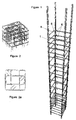
- Figures 1, 2, 2a present the known stirrups.
- FIG. 3 shows a stirrup according to the invention fastened to the principal reinforcement rods of a column and figures 3a shows schematically this stirrup.
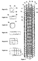
- Figures 4a, 4b, 4c, 4d, 4e show schematically stirrups according to the invention for the reinforcement of columns.
- Figures 8, 8a, 9 present spiral stirrups, adequate for footings or beams.
- Figures 10, 10a present a spiral stirrup, adequate for a load-bearing wall.
- Figures 11a, 11b, 11c, 11d, 11e, 11f show stirrups according to the invention for the reinforcement of load bearing elements having a Z-shaped cross section.
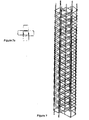
- Figures 12 present a side view of a spiral stirrup according to figure 3 with variable pitch.
- Figure 13 shows a stirrup according to the invention consisting of two spiral elemets shown in figures 13a and 13b.
- Figures 14a, 15a, 16a, 17a present a method of reinforcing load-bearing elements in accordance to the invention applied to the elements shown in figures 14, 15, 16, and 17 .
- FIG. 3 shows a stirrup according to the invention.
- the spiral stirrup of this figure has consecutive alternating windings 7a and 7b.
- the set of windings 7a forms a cage 5a to house the principal rods 1a of the reinforcement.
- the windings 7a are tightened around the rods 1a and it could be enough to fasten each winding even to three rods.
- the set of windings 7b form a cage 5b to house the principal rods 1b of the reinforcement.
- the stirrup includes two cages 5a, 5b, whereby each one of the cages 5a, 5b is formed by the alternating windings 7a, 7b respectively.
- Figure 3a shows schematically a cross sectional view of the stirrup shown in figure 3
- figures 4a, 4b, 4c, 4d, 4e show cross sectional views of other stirrups to be used for the reinforcement of columns
- the stirrup of figure 4a has two cages 5a, 5b with overlapping cross sections
- figure 4b shows a stirrup with an almost rectangular cage 5b within a polygonal cage 5a.
- Such a stirrup may be formed with a circular or elliptical outer cage.
- Further stirrups for columns with rectangular cross-sections are shown in figures 4c, 4d and 4e .
- Figures 5, 5a, 5b, 5c present spiral stirrups having L-shaped cross-sections comprising two (see figure 5a), three (see figure 5b) or four (see figure 5c, cages 5a, 5b, 5c, 5d) cages.
- Figures 6, 6a, 6b, 6c, 6d, 6e present spiral stirrups with T-shaped cross sections, and figures 7, 7a a stirrup with a crosshead cross-section.
- T-shaped spiral stirrups, which are also used for the reinforcement of footings, have an excellent performance when they carry simultaneously shear, torsional and flexural loads.
- FIG 8, 8a show a spiral stirrup to be used for the reinforcement of a beam or footing, with two overlapping cages 5a, 5b, according the invention With this arrangement a single spiral may be used for each footing or beam.
- Figure 9 shows a spiral stirrup with three cages 5a, 5b, 5c to be used for the reinforcement of a beam of a bridge.
- Figure 10 shows the axonometric representation and plan view of a concrete shear wall with a spiral stirrup shown schematically in figure 10a.
- Figures 11a, 11b, 11c, 11d, 11e, 11f show indicative representation of spirals for Z-shaped columns, which are often used at the corners of buildings.
- the pitch of the windings may be uniform or variable, as shown in figure 12 .
- the variation in pitch may be effected either during production or during the reinforcing of the load-bearing element.
- Figure 12 shows the spiral stirrup of figure 3. divided in parts with constant pitch. For example for a distance of 0.5 m in the base and 0,5 m in the top of the member the pitch equals to 10cm and 12 cm respectively, whereas along the middle portion of the stirrup, which extends along a length of 2 meters, the pitch is 20 cm.
- the stirrup of figure 12 may be used for the reinforcement of a column, beam or other structural elements.
- the stirrup of the invention may be manufactured by a continuous extruded steel rod or by parts. With this arrangement the spiral is constructed by a number of spiral elements manufactured individually.
- the spiral elements may be constructed by rod with the same or different cross-section and may have the same or different pitch.
- the spiral elements are placed side by side along their longitudinal direction and their ends are joint, so that one spiral element extends on one side of the joint and the other on the other side thereof.
- each end of the spiral elements is provided with a winding having a very small or even zero pitch which are welded together to effect the joint.
- Joint of the spiral elements may be also effected by the combination of the two previous arrangements.
- Figure 13 shows a stirrup made of the two spiral elements 3' , 3" , shown schematically in figures 13a, 13b, which is to be used for the reinforcement of beams, columns or other structural elements.
- the joint of spiral elements to produce a spiral with the features of the invention may be effected in site or it may be prefabricated
- Figures 14a, 15a, 16a, 17a show the application of spiral strirrups in accordance with the invention, for the reinforcement of the shear wall elements shown in figures 14, 15, 16, and 17 respectively.
- the walls may be of large sizes and in general they may have a rectangular, angular, lift type etc. cross sections.
- the combination of regular size spiral stirrups with longitudinal rods 4 which may have hooks 6' - 90° or 135° or other angle - at their ends effects the reinforcement of the walls.
- Other ways of attachment of the rods to the stirrups are also possible.
- Spiral stirrups are placed at shear walls ends and they tied or welded to the longitudinal rods, which in the case of te examples shown in the figures, are normal or almost normal to the longitudinal direction of the stirrups.
- stirrups of the invention may be used for the reinforcemnet of prefabricated load bearing structural elements.
Landscapes
- Engineering & Computer Science (AREA)
- Architecture (AREA)
- Civil Engineering (AREA)
- Structural Engineering (AREA)
- Business, Economics & Management (AREA)
- Emergency Management (AREA)
- Environmental & Geological Engineering (AREA)
- Reinforcement Elements For Buildings (AREA)
- Rod-Shaped Construction Members (AREA)
- Clamps And Clips (AREA)
- Supports For Pipes And Cables (AREA)
- Working Measures On Existing Buildindgs (AREA)
Applications Claiming Priority (3)
| Application Number | Priority Date | Filing Date | Title |
|---|---|---|---|
| GR97100003 | 1997-01-03 | ||
| GR97100003 | 1997-01-03 | ||
| PCT/GR1997/000043 WO1998029618A1 (en) | 1997-01-03 | 1997-12-31 | Antiseismic spiral stirrups for reinforcement of load bearing structural elements |
Publications (2)
| Publication Number | Publication Date |
|---|---|
| EP0956406A1 EP0956406A1 (en) | 1999-11-17 |
| EP0956406B1 true EP0956406B1 (en) | 2001-05-02 |
Family
ID=10942857
Family Applications (1)
| Application Number | Title | Priority Date | Filing Date |
|---|---|---|---|
| EP97949074A Expired - Lifetime EP0956406B1 (en) | 1997-01-03 | 1997-12-31 | Antiseismic spiral stirrups for reinforcement of load bearing structural elements |
Country Status (12)
| Country | Link |
|---|---|
| US (1) | US6293071B1 (pt) |
| EP (1) | EP0956406B1 (pt) |
| AT (1) | ATE200921T1 (pt) |
| AU (1) | AU757707B2 (pt) |
| CA (1) | CA2276443C (pt) |
| DE (1) | DE69704720T2 (pt) |
| DK (1) | DK0956406T3 (pt) |
| ES (1) | ES2158602T3 (pt) |
| GR (1) | GR1002860B (pt) |
| NZ (1) | NZ336986A (pt) |
| PT (1) | PT956406E (pt) |
| WO (1) | WO1998029618A1 (pt) |
Cited By (1)
| Publication number | Priority date | Publication date | Assignee | Title |
|---|---|---|---|---|
| DE102005030409B4 (de) * | 2005-06-30 | 2009-12-31 | Technische Universität München | Wendelförmiges Bewehrungselement |
Families Citing this family (43)
| Publication number | Priority date | Publication date | Assignee | Title |
|---|---|---|---|---|
| GR1003706B (el) * | 1997-11-05 | 2001-10-24 | Κυψελοειδεις συνδετηρες δομικων εργων | |
| US6820111B1 (en) * | 1999-12-07 | 2004-11-16 | Microsoft Corporation | Computer user interface architecture that saves a user's non-linear navigation history and intelligently maintains that history |
| GR1003584B (el) * | 2000-05-29 | 2001-05-22 | Αν. Γεωργιος Κασταναρας | Στοιχεια απο βεργα μπετοσιδηρου για την κατασκευη οπλισμου σκυροδεματος. |
| KR20030018728A (ko) * | 2001-08-31 | 2003-03-06 | 한국도로공사 | 철근콘크리트 기둥의 횡방향 보강구조 |
| AU2002362315C1 (en) * | 2001-09-19 | 2005-11-17 | Alexee A. Gulikov | Spiral ties for reinforced columns |
| AUPR772201A0 (en) * | 2001-09-19 | 2001-10-11 | Gulikov, Alexee Anatolievich | Spiralnet |
| US20050257482A1 (en) * | 2003-04-14 | 2005-11-24 | Galluccio Anton M | Broken-spiral stirrup and method for implementing the reinforcement of concrete structures |
| ITAR20030018A1 (it) * | 2003-04-14 | 2003-07-14 | Anton Massimo Galluccio | Staffatura ad elica spezzata e metodo per la realizzazione della armatura di strutture in calcestruzzo |
| DE10324291A1 (de) * | 2003-05-21 | 2004-12-16 | Weiske, Rainer, Dipl.-Ing. | Bewehrungselement |
| ATE364754T1 (de) * | 2003-06-02 | 2007-07-15 | Yurkevich Engineering Bureau L | Stahlbetonstütze in erdaushebungen und verfahren zum bauen dieser stütze |
| DE10337539A1 (de) * | 2003-08-06 | 2005-02-24 | Alfredo Jimenez Anguita | Spiralförmige Körper, die i.d.R. Gefüllt, in der Geotechnik, im Garten- und Landschaftsbau und/oder im Gebäudebau eingesetzt werden |
| BRPI0403995A (pt) * | 2004-07-12 | 2006-02-21 | Bmp Siderurgia S A | vergalhão com núcleo octogonal destinado à construção civil |
| EP1848867B1 (en) * | 2005-01-25 | 2017-01-04 | Sidenor SA | Strengthening structure |
| US7856778B2 (en) * | 2005-05-25 | 2010-12-28 | University Of Utah Foundation | FRP composite wall panels and methods of manufacture |
| GR1005481B (el) * | 2005-07-28 | 2007-04-02 | Συστημα και μεθοδος για την εκπονηση και διαχειριση μελετων εφαρμογης για την οπλιση κτιριακων εργων. | |
| US20070039276A1 (en) * | 2005-08-19 | 2007-02-22 | R2M2 Rebar And Stressing, Inc. | Concrete reinforcer and method |
| CA2574722C (en) * | 2007-01-22 | 2009-12-01 | Ideas Without Borders Inc. | System for reinforcing a building structural component |
| US20090178356A1 (en) * | 2008-01-15 | 2009-07-16 | Baumann Hanns U | Pre-cast concrete column and method of fabrication |
| ES2368048B1 (es) * | 2008-11-18 | 2012-04-30 | Prensoland, S.A | Placa alveolar antis�?smica. |
| CH699932B1 (de) * | 2008-11-28 | 2012-11-30 | Markus Ausderau | Bewehrungsvorrichtung. |
| US8381479B1 (en) | 2009-09-28 | 2013-02-26 | Felix E. Ferrer | Pre-fabricated modular reinforcement cages for concrete structures |
| IT1400333B1 (it) * | 2009-11-13 | 2013-05-24 | A W M Spa | Metodo e macchina per l'assemblaggio automatico di gabbie complesse formate da reti metalliche elettrosaldate. |
| EP2588677B1 (en) * | 2010-07-01 | 2016-03-16 | Sidenor S.A. | Structure for strengthening concrete and method for producing a structure for strengthening concrete |
| AU2012339603B2 (en) * | 2011-11-20 | 2016-04-14 | Alexee GULIKOV | Steel reinforcing structure for concrete |
| NZ610739A (en) | 2012-05-18 | 2014-04-30 | Neturen Co Ltd | Rebar structure and reinforced concrete member |
| KR101253255B1 (ko) * | 2012-09-13 | 2013-04-10 | (주)목양엔지니어링건축사사무소 | 횡구속 및 하이브리드 섬유혼입을 통한 고강도 콘크리트의 내화성능 향상공법 |
| US8973322B2 (en) * | 2013-01-16 | 2015-03-10 | Rupert Heron | Masonry units and structures formed therefrom |
| KR20150051434A (ko) * | 2013-11-04 | 2015-05-13 | 삼성물산 주식회사 | 삼각 철근망 배근에 의한 내진 중실 철근콘크리트 기둥 및 이의 시공방법 |
| US9267287B1 (en) * | 2014-01-22 | 2016-02-23 | Steven James Bongiorno | Pre-fabricated threaded bar assemblies |
| CN104295002B (zh) * | 2014-09-17 | 2016-06-29 | 华南理工大学 | 内设局部约束的高强化再生混合钢管砼轴压柱及施工工艺 |
| US9909693B2 (en) * | 2015-02-26 | 2018-03-06 | Engineered Wire Products, Inc. | Concrete reinforcement elements and structures |
| US9890545B1 (en) * | 2016-11-14 | 2018-02-13 | Steven James Bongiorno | Erection system |
| TWI674345B (zh) * | 2018-01-23 | 2019-10-11 | 潤弘精密工程事業股份有限公司 | 梁柱接頭結構及其施工方法 |
| CN108265744B (zh) * | 2018-03-13 | 2024-07-12 | 国家电网公司 | 一种架空输电线路phc管桩基础基桩与承台的连接结构 |
| TWM565222U (zh) * | 2018-03-26 | 2018-08-11 | 潤弘精密工程事業股份有限公司 | 梁柱接頭結構 |
| CN111636562A (zh) * | 2020-05-27 | 2020-09-08 | 安徽富煌钢构股份有限公司 | 一种装配式高层钢结构住宅双钢板混凝土组合剪力墙框架结构 |
| TWI758834B (zh) * | 2020-08-24 | 2022-03-21 | 江文財 | 柱中柱組合型圍束之結合構造 |
| CN112376785B (zh) * | 2020-11-13 | 2022-02-18 | 中国有色金属工业第六冶金建设有限公司 | 装配式轻钢混凝土组合墙 |
| CN112854605A (zh) * | 2021-01-12 | 2021-05-28 | 吉林建筑大学 | 一种混凝土柱的复合螺旋箍筋及其绕制方法 |
| CN113338542B (zh) * | 2021-06-15 | 2023-08-18 | 三一筑工科技股份有限公司 | 一种钢筋笼及其成型方法 |
| TWI772197B (zh) * | 2021-10-08 | 2022-07-21 | 建國工程股份有限公司 | 用於樑鋼筋系統的箍筋模組及樑鋼筋系統的製造方法 |
| TWI780946B (zh) * | 2021-10-12 | 2022-10-11 | 建國工程股份有限公司 | 用於樑鋼筋系統的箍筋模組及樑鋼筋系統的製造方法 |
| US20240254769A1 (en) * | 2022-03-25 | 2024-08-01 | Shahn Christian Andersen | Modular Prefabricated Rebar Component |
Family Cites Families (6)
| Publication number | Priority date | Publication date | Assignee | Title |
|---|---|---|---|---|
| AU5867469A (en) * | 1969-07-28 | 1971-02-04 | Leslie Bernhard Kanzler Graham | Improved reinforcement for concrete forms |
| US3882905A (en) * | 1973-03-12 | 1975-05-13 | Stressed Pipe Research Inc | Reinforcing cage |
| DE2646272A1 (de) * | 1976-10-14 | 1978-04-20 | Dyckerhoff & Widmann Ag | Verwendung einer zylindermantelfoermigen bewehrungseinheit zur herstellung eines rohrfoermigen hohlkoerpers aus spannbeton |
| US4119764A (en) * | 1976-11-23 | 1978-10-10 | Neturen Company Ltd. | Helical reinforcing bar for steel cage in concrete structure |
| SE415992B (sv) * | 1977-02-07 | 1980-11-17 | A Betong Ab | Sett att tillverka en armeringsbur till betongstoplr jemte fixtur for utforande av settet |
| FI69179C (fi) * | 1984-01-24 | 1985-12-10 | Rakennusvalmiste Oy | Foerfarande foer tillverkning av spiralarmeringar och av dessabestaoende kombinerad spiralmeringsanordning |
-
1997
- 1997-01-03 GR GR970100003A patent/GR1002860B/el not_active IP Right Cessation
- 1997-12-31 AT AT97949074T patent/ATE200921T1/de not_active IP Right Cessation
- 1997-12-31 US US09/331,805 patent/US6293071B1/en not_active Expired - Fee Related
- 1997-12-31 CA CA002276443A patent/CA2276443C/en not_active Expired - Fee Related
- 1997-12-31 EP EP97949074A patent/EP0956406B1/en not_active Expired - Lifetime
- 1997-12-31 WO PCT/GR1997/000043 patent/WO1998029618A1/en active IP Right Grant
- 1997-12-31 DK DK97949074T patent/DK0956406T3/da active
- 1997-12-31 PT PT97949074T patent/PT956406E/pt unknown
- 1997-12-31 DE DE69704720T patent/DE69704720T2/de not_active Ceased
- 1997-12-31 AU AU78919/98A patent/AU757707B2/en not_active Ceased
- 1997-12-31 ES ES97949074T patent/ES2158602T3/es not_active Expired - Lifetime
- 1997-12-31 NZ NZ336986A patent/NZ336986A/xx unknown
Cited By (1)
| Publication number | Priority date | Publication date | Assignee | Title |
|---|---|---|---|---|
| DE102005030409B4 (de) * | 2005-06-30 | 2009-12-31 | Technische Universität München | Wendelförmiges Bewehrungselement |
Also Published As
| Publication number | Publication date |
|---|---|
| DE69704720T2 (de) | 2001-12-06 |
| GR1002860B (el) | 1998-02-12 |
| ES2158602T3 (es) | 2001-09-01 |
| PT956406E (pt) | 2001-10-31 |
| NZ336986A (en) | 2000-12-22 |
| ATE200921T1 (de) | 2001-05-15 |
| DE69704720D1 (de) | 2001-06-07 |
| WO1998029618A1 (en) | 1998-07-09 |
| CA2276443A1 (en) | 1998-07-09 |
| AU7891998A (en) | 1998-07-31 |
| US6293071B1 (en) | 2001-09-25 |
| CA2276443C (en) | 2006-02-14 |
| AU757707B2 (en) | 2003-03-06 |
| DK0956406T3 (da) | 2001-08-20 |
| EP0956406A1 (en) | 1999-11-17 |
Similar Documents
| Publication | Publication Date | Title |
|---|---|---|
| EP0956406B1 (en) | Antiseismic spiral stirrups for reinforcement of load bearing structural elements | |
| EP0823954B1 (en) | Improvements in or relating to reinforced concrete structural elements | |
| US7493735B2 (en) | Spiral stirrup and steel element combination structure system | |
| US8769906B2 (en) | Reinforcement system for concrete structures and a method for reinforcing an elongate concrete structure | |
| US4586307A (en) | Prefabricated ceiling element for ceilings in buildings | |
| KR102459913B1 (ko) | 철근콘크리트 기둥의 내진 보강 구조 및 이의 시공 방법 | |
| KR101177316B1 (ko) | 기둥?슬래브 접합부의 수직걸림형 전단보강체 | |
| KR101188367B1 (ko) | 무량판 슬래브 펀칭 전단보강체 | |
| WO1992012303A1 (en) | Arrangement of building element | |
| HUT50913A (en) | Lattice girder for producing partly prefabricated reinforced concrete floors | |
| JP3433440B2 (ja) | コンクリート構造物の構造部材の施工法 | |
| KR200200417Y1 (ko) | 철근콘크리트 슬래브의 데크 거더 | |
| JPH08338104A (ja) | 強化したコンクリート柱と、その強化方法 | |
| JPS603844Y2 (ja) | 補強コンクリ−ト構造 | |
| JPH0344881Y2 (pt) | ||
| KR101858557B1 (ko) | 다중 x형 보강철근체가 구비된 철근콘크리트 기둥 | |
| JPH0478771B2 (pt) | ||
| JPH06146472A (ja) | プレキャスト鉄筋コンクリート梁 | |
| JP2000248510A (ja) | 箱形主桁の配筋構造 | |
| KR930003882Y1 (ko) | 철근 트러스판 | |
| KR100376930B1 (ko) | 철근 콘크리트 슬래브의 데크 패널 | |
| RU2045633C1 (ru) | Сборное железобетонное перекрытие | |
| JPH0534464B2 (pt) | ||
| JP2003138684A (ja) | プレキャストコンクリートスラブ | |
| KR930006957B1 (ko) | 콘크리트 구조물용 절곡 메탈라스 |
Legal Events
| Date | Code | Title | Description |
|---|---|---|---|
| PUAI | Public reference made under article 153(3) epc to a published international application that has entered the european phase |
Free format text: ORIGINAL CODE: 0009012 |
|
| 17P | Request for examination filed |
Effective date: 19990601 |
|
| AK | Designated contracting states |
Kind code of ref document: A1 Designated state(s): AT BE CH DE DK ES FI FR GB GR IE IT LI NL PT SE |
|
| AX | Request for extension of the european patent |
Free format text: AL PAYMENT 19990527;MK PAYMENT 19990527;RO PAYMENT 19990527 |
|
| 17Q | First examination report despatched |
Effective date: 19991202 |
|
| GRAG | Despatch of communication of intention to grant |
Free format text: ORIGINAL CODE: EPIDOS AGRA |
|
| GRAG | Despatch of communication of intention to grant |
Free format text: ORIGINAL CODE: EPIDOS AGRA |
|
| GRAG | Despatch of communication of intention to grant |
Free format text: ORIGINAL CODE: EPIDOS AGRA |
|
| GRAH | Despatch of communication of intention to grant a patent |
Free format text: ORIGINAL CODE: EPIDOS IGRA |
|
| GRAH | Despatch of communication of intention to grant a patent |
Free format text: ORIGINAL CODE: EPIDOS IGRA |
|
| GRAA | (expected) grant |
Free format text: ORIGINAL CODE: 0009210 |
|
| AK | Designated contracting states |
Kind code of ref document: B1 Designated state(s): AT BE CH DE DK ES FI FR GB GR IE IT LI NL PT SE |
|
| AX | Request for extension of the european patent |
Free format text: AL PAYMENT 19990527;MK PAYMENT 19990527;RO PAYMENT 19990527 |
|
| REF | Corresponds to: |
Ref document number: 200921 Country of ref document: AT Date of ref document: 20010515 Kind code of ref document: T |
|
| REG | Reference to a national code |
Ref country code: CH Ref legal event code: EP |
|
| REF | Corresponds to: |
Ref document number: 69704720 Country of ref document: DE Date of ref document: 20010607 |
|
| REG | Reference to a national code |
Ref country code: IE Ref legal event code: FG4D |
|
| ET | Fr: translation filed | ||
| REG | Reference to a national code |
Ref country code: CH Ref legal event code: NV Representative=s name: ISLER & PEDRAZZINI AG |
|
| ITF | It: translation for a ep patent filed | ||
| PG25 | Lapsed in a contracting state [announced via postgrant information from national office to epo] |
Ref country code: GR Free format text: LAPSE BECAUSE OF FAILURE TO SUBMIT A TRANSLATION OF THE DESCRIPTION OR TO PAY THE FEE WITHIN THE PRESCRIBED TIME-LIMIT Effective date: 20010803 |
|
| REG | Reference to a national code |
Ref country code: DK Ref legal event code: T3 |
|
| REG | Reference to a national code |
Ref country code: ES Ref legal event code: FG2A Ref document number: 2158602 Country of ref document: ES Kind code of ref document: T3 |
|
| REG | Reference to a national code |
Ref country code: PT Ref legal event code: SC4A Free format text: AVAILABILITY OF NATIONAL TRANSLATION Effective date: 20010802 |
|
| REG | Reference to a national code |
Ref country code: GB Ref legal event code: IF02 |
|
| PLBE | No opposition filed within time limit |
Free format text: ORIGINAL CODE: 0009261 |
|
| STAA | Information on the status of an ep patent application or granted ep patent |
Free format text: STATUS: NO OPPOSITION FILED WITHIN TIME LIMIT |
|
| 26N | No opposition filed | ||
| PGFP | Annual fee paid to national office [announced via postgrant information from national office to epo] |
Ref country code: PT Payment date: 20051103 Year of fee payment: 9 Ref country code: IE Payment date: 20051103 Year of fee payment: 9 |
|
| PGFP | Annual fee paid to national office [announced via postgrant information from national office to epo] |
Ref country code: FR Payment date: 20051114 Year of fee payment: 9 |
|
| PGFP | Annual fee paid to national office [announced via postgrant information from national office to epo] |
Ref country code: NL Payment date: 20051130 Year of fee payment: 9 |
|
| PGFP | Annual fee paid to national office [announced via postgrant information from national office to epo] |
Ref country code: GB Payment date: 20051202 Year of fee payment: 9 |
|
| PGFP | Annual fee paid to national office [announced via postgrant information from national office to epo] |
Ref country code: SE Payment date: 20051206 Year of fee payment: 9 |
|
| PGFP | Annual fee paid to national office [announced via postgrant information from national office to epo] |
Ref country code: FI Payment date: 20051207 Year of fee payment: 9 |
|
| PGFP | Annual fee paid to national office [announced via postgrant information from national office to epo] |
Ref country code: CH Payment date: 20051221 Year of fee payment: 9 |
|
| PGFP | Annual fee paid to national office [announced via postgrant information from national office to epo] |
Ref country code: BE Payment date: 20051223 Year of fee payment: 9 Ref country code: AT Payment date: 20051223 Year of fee payment: 9 Ref country code: ES Payment date: 20051223 Year of fee payment: 9 Ref country code: DK Payment date: 20051223 Year of fee payment: 9 |
|
| PG25 | Lapsed in a contracting state [announced via postgrant information from national office to epo] |
Ref country code: IT Free format text: LAPSE BECAUSE OF NON-PAYMENT OF DUE FEES Effective date: 20051231 |
|
| PGFP | Annual fee paid to national office [announced via postgrant information from national office to epo] |
Ref country code: DE Payment date: 20060216 Year of fee payment: 9 |
|
| PG25 | Lapsed in a contracting state [announced via postgrant information from national office to epo] |
Ref country code: DE Free format text: THE PATENT HAS BEEN ANNULLED BY A DECISION OF A NATIONAL AUTHORITY Effective date: 20060803 |
|
| PG25 | Lapsed in a contracting state [announced via postgrant information from national office to epo] |
Ref country code: LI Free format text: LAPSE BECAUSE OF NON-PAYMENT OF DUE FEES Effective date: 20061231 Ref country code: FI Free format text: LAPSE BECAUSE OF NON-PAYMENT OF DUE FEES Effective date: 20061231 Ref country code: CH Free format text: LAPSE BECAUSE OF NON-PAYMENT OF DUE FEES Effective date: 20061231 Ref country code: BE Free format text: LAPSE BECAUSE OF NON-PAYMENT OF DUE FEES Effective date: 20061231 |
|
| PG25 | Lapsed in a contracting state [announced via postgrant information from national office to epo] |
Ref country code: SE Free format text: LAPSE BECAUSE OF NON-PAYMENT OF DUE FEES Effective date: 20070101 Ref country code: IE Free format text: LAPSE BECAUSE OF NON-PAYMENT OF DUE FEES Effective date: 20070101 |
|
| PG25 | Lapsed in a contracting state [announced via postgrant information from national office to epo] |
Ref country code: NL Free format text: LAPSE BECAUSE OF NON-PAYMENT OF DUE FEES Effective date: 20070701 |
|
| PG25 | Lapsed in a contracting state [announced via postgrant information from national office to epo] |
Ref country code: PT Free format text: LAPSE BECAUSE OF NON-PAYMENT OF DUE FEES Effective date: 20070702 |
|
| REG | Reference to a national code |
Ref country code: PT Ref legal event code: MM4A Free format text: LAPSE DUE TO NON-PAYMENT OF FEES Effective date: 20070702 |
|
| REG | Reference to a national code |
Ref country code: DK Ref legal event code: EBP |
|
| REG | Reference to a national code |
Ref country code: CH Ref legal event code: PL |
|
| GBPC | Gb: european patent ceased through non-payment of renewal fee |
Effective date: 20061231 |
|
| NLV4 | Nl: lapsed or anulled due to non-payment of the annual fee |
Effective date: 20070701 |
|
| EUG | Se: european patent has lapsed | ||
| REG | Reference to a national code |
Ref country code: FR Ref legal event code: ST Effective date: 20070831 |
|
| REG | Reference to a national code |
Ref country code: IE Ref legal event code: MM4A |
|
| PG25 | Lapsed in a contracting state [announced via postgrant information from national office to epo] |
Ref country code: GB Free format text: LAPSE BECAUSE OF NON-PAYMENT OF DUE FEES Effective date: 20061231 Ref country code: AT Free format text: LAPSE BECAUSE OF NON-PAYMENT OF DUE FEES Effective date: 20061231 |
|
| BERE | Be: lapsed |
Owner name: *KONSTANTINIDIS APOSTOLOS Effective date: 20061231 |
|
| PG25 | Lapsed in a contracting state [announced via postgrant information from national office to epo] |
Ref country code: DK Free format text: LAPSE BECAUSE OF NON-PAYMENT OF DUE FEES Effective date: 20070102 |
|
| REG | Reference to a national code |
Ref country code: ES Ref legal event code: FD2A Effective date: 20070102 |
|
| PG25 | Lapsed in a contracting state [announced via postgrant information from national office to epo] |
Ref country code: FR Free format text: LAPSE BECAUSE OF NON-PAYMENT OF DUE FEES Effective date: 20070102 Ref country code: ES Free format text: LAPSE BECAUSE OF NON-PAYMENT OF DUE FEES Effective date: 20070102 |