EP0956406B1 - Antiseismic spiral stirrups for reinforcement of load bearing structural elements - Google Patents
Antiseismic spiral stirrups for reinforcement of load bearing structural elements Download PDFInfo
- Publication number
- EP0956406B1 EP0956406B1 EP97949074A EP97949074A EP0956406B1 EP 0956406 B1 EP0956406 B1 EP 0956406B1 EP 97949074 A EP97949074 A EP 97949074A EP 97949074 A EP97949074 A EP 97949074A EP 0956406 B1 EP0956406 B1 EP 0956406B1
- Authority
- EP
- European Patent Office
- Prior art keywords
- stirrup
- elements
- windings
- load bearing
- stirrups
- Prior art date
- Legal status (The legal status is an assumption and is not a legal conclusion. Google has not performed a legal analysis and makes no representation as to the accuracy of the status listed.)
- Expired - Lifetime
Links
Images


Classifications
-
- E—FIXED CONSTRUCTIONS
- E04—BUILDING
- E04H—BUILDINGS OR LIKE STRUCTURES FOR PARTICULAR PURPOSES; SWIMMING OR SPLASH BATHS OR POOLS; MASTS; FENCING; TENTS OR CANOPIES, IN GENERAL
- E04H9/00—Buildings, groups of buildings or shelters adapted to withstand or provide protection against abnormal external influences, e.g. war-like action, earthquake or extreme climate
- E04H9/02—Buildings, groups of buildings or shelters adapted to withstand or provide protection against abnormal external influences, e.g. war-like action, earthquake or extreme climate withstanding earthquake or sinking of ground
-
- E—FIXED CONSTRUCTIONS
- E04—BUILDING
- E04C—STRUCTURAL ELEMENTS; BUILDING MATERIALS
- E04C5/00—Reinforcing elements, e.g. for concrete; Auxiliary elements therefor
- E04C5/01—Reinforcing elements of metal, e.g. with non-structural coatings
- E04C5/02—Reinforcing elements of metal, e.g. with non-structural coatings of low bending resistance
-
- E—FIXED CONSTRUCTIONS
- E04—BUILDING
- E04C—STRUCTURAL ELEMENTS; BUILDING MATERIALS
- E04C5/00—Reinforcing elements, e.g. for concrete; Auxiliary elements therefor
- E04C5/01—Reinforcing elements of metal, e.g. with non-structural coatings
- E04C5/06—Reinforcing elements of metal, e.g. with non-structural coatings of high bending resistance, i.e. of essentially three-dimensional extent, e.g. lattice girders
- E04C5/0604—Prismatic or cylindrical reinforcement cages composed of longitudinal bars and open or closed stirrup rods
- E04C5/0609—Closed cages composed of two or more coacting cage parts, e.g. transversally hinged or nested parts
-
- E—FIXED CONSTRUCTIONS
- E04—BUILDING
- E04C—STRUCTURAL ELEMENTS; BUILDING MATERIALS
- E04C5/00—Reinforcing elements, e.g. for concrete; Auxiliary elements therefor
- E04C5/01—Reinforcing elements of metal, e.g. with non-structural coatings
- E04C5/06—Reinforcing elements of metal, e.g. with non-structural coatings of high bending resistance, i.e. of essentially three-dimensional extent, e.g. lattice girders
- E04C5/0604—Prismatic or cylindrical reinforcement cages composed of longitudinal bars and open or closed stirrup rods
- E04C5/0618—Closed cages with spiral- or coil-shaped stirrup rod
Abstract
Description
Claims (19)
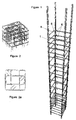
- Stirrup for reinforcing load bearing elements consisting of a plurality of consecutive windings (7a, 7b) disposed along the longitudinal direction of the stirrup and having a continuous cross section, so that the stirrup has a spiral form, characterized in that the windings of the stirrup form a plurality of discrete cages (5a, 5b) to house the main reinforcement rods (1a, 1b) of the load bearing element.
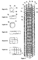
- Stirrup according to claim 1, whereby the stirrup comprises n cylindrically- or approximately cylindrically-shaped cages, wherein is an integer greater or equal to 2, and whereby the projections of each n-th winding provided along a portion at least of the length of the stirrup, on a transverse plane coincide.
- Stirrup according to claim 1 or 2, whereby the stirrup comprises two and only two cages to house the main reinforcement rods of the load bearing element.
- Stirrup according to claim 1 or 2, whereby the stirrup comprises at least four cages (5a, 5b, 5c, 5d) to house the main reinforcement rods of the load bearing element.
- Stirrup according to any of the preceding claims, whereby the projection of the stirrup on a transverse plane coincides to the cross section of a load bearing element comprising at least one web and at least one flange.
- Stirrup according to any of the claims 1, 2, 3, 5 whereby the shape of the windings on a transverse plane is orthogonal and adjacent windings are so disposed, that the long dimension of each winding is normal to the long dimension of its adjacent windings, so that the projection of the stirrup on the transverse plane is T like.
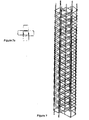
- Stirrup according to claim 1 or 2, whereby the stirrup comprises an outer cage which houses all other cages of the stirrup.
- Stirrup according to any of the preceding claims, whereby the stirrup is made of a continuous extruded steel rod.
- Stirrup according to any of the claims 1 to 7, whereby the stirrups are made from composite material.
- Stirrup according to any of preceding claims, whereby the windings are disposed on substantially transverse planes and consecutive windings are joined by substantially longitudinal elements.
- Stirrup according to any of preceding claims, whereby the distance between consecutive windings is uniform.
- Stirrup according to any of the claims 1 to 10, whereby the distance between consecutive windings is variable.
- Stirrup according to any of preceding claims, whereby the stirrup comprises two spiral elements (3', 3") disposed longitudinally and joined at their ends, so that the one of the two elements extends towards one side of the said joined ends and the other of the two elements extends towards the other side of the said joined ends.
- Stirrup according to claim 13, whereby the two spiral elements is welded together.
- Stirrup according to claim 13 or 14, whereby the first and/or the second of said elements are stirrups according to any of the claims 1 to 12.
- A prefabricated load bearing element comprising a stirrup in accordance with any of the claims 1 to 15.
- Method of reinforcing of shear wall elements using the stirrups of any of the claims 1 to 15, whereby the reinforcement of the wall is effected by joining at least two of the said stirrups with reinforcement rods (4).
- Method of reinforcing a load bearing element whereby the principal rod elements of the reinforcement are housed within the windings of a spiral shaped stirrup with a plurality of consecutive windings having a continuous cross section, characterized in that the stirrup comprises a plurality of cages (5a, 5b), with each cage (5a, 5b) tightening a different set of principal rod elements.
- A load bearing element whereby the principal bar elements of the reinforcement are housed within the windings of a spiral shaped stirrup with a plurality of consecutive windings having a continuous cross section, characterized in that the stirrup comprises a plurality of cages (5a, 5b), with each cage (5a, 5b) tightening a different set of principal rod elements.
Applications Claiming Priority (3)
| Application Number | Priority Date | Filing Date | Title |
|---|---|---|---|
| GR97100003 | 1997-01-03 | ||
| GR97100003 | 1997-01-03 | ||
| PCT/GR1997/000043 WO1998029618A1 (en) | 1997-01-03 | 1997-12-31 | Antiseismic spiral stirrups for reinforcement of load bearing structural elements |
Publications (2)
| Publication Number | Publication Date |
|---|---|
| EP0956406A1 EP0956406A1 (en) | 1999-11-17 |
| EP0956406B1 true EP0956406B1 (en) | 2001-05-02 |
Family
ID=10942857
Family Applications (1)
| Application Number | Title | Priority Date | Filing Date |
|---|---|---|---|
| EP97949074A Expired - Lifetime EP0956406B1 (en) | 1997-01-03 | 1997-12-31 | Antiseismic spiral stirrups for reinforcement of load bearing structural elements |
Country Status (12)
| Country | Link |
|---|---|
| US (1) | US6293071B1 (en) |
| EP (1) | EP0956406B1 (en) |
| AT (1) | ATE200921T1 (en) |
| AU (1) | AU757707B2 (en) |
| CA (1) | CA2276443C (en) |
| DE (1) | DE69704720T2 (en) |
| DK (1) | DK0956406T3 (en) |
| ES (1) | ES2158602T3 (en) |
| GR (1) | GR1002860B (en) |
| NZ (1) | NZ336986A (en) |
| PT (1) | PT956406E (en) |
| WO (1) | WO1998029618A1 (en) |
Cited By (1)
| Publication number | Priority date | Publication date | Assignee | Title |
|---|---|---|---|---|
| DE102005030409B4 (en) * | 2005-06-30 | 2009-12-31 | Technische Universität München | Spiral reinforcing element |
Families Citing this family (40)
| Publication number | Priority date | Publication date | Assignee | Title |
|---|---|---|---|---|
| GR1003706B (en) * | 1997-11-05 | 2001-10-24 | Cellular stirrups and ties for structures | |
| US6820111B1 (en) * | 1999-12-07 | 2004-11-16 | Microsoft Corporation | Computer user interface architecture that saves a user's non-linear navigation history and intelligently maintains that history |
| GR1003584B (en) * | 2000-05-29 | 2001-05-22 | Αν. Γεωργιος Κασταναρας | Elements from concrete iron bar for the construction of concrete reinforcement |
| KR20030018728A (en) * | 2001-08-31 | 2003-03-06 | 한국도로공사 | Lateral reinforcement structure of reinforced concrete pillar |
| AU2002362315C1 (en) * | 2001-09-19 | 2005-11-17 | Alexee A. Gulikov | Spiral ties for reinforced columns |
| AUPR772201A0 (en) * | 2001-09-19 | 2001-10-11 | Gulikov, Alexee Anatolievich | Spiralnet |
| US20050257482A1 (en) * | 2003-04-14 | 2005-11-24 | Galluccio Anton M | Broken-spiral stirrup and method for implementing the reinforcement of concrete structures |
| ITAR20030018A1 (en) * | 2003-04-14 | 2003-07-14 | Anton Massimo Galluccio | BROKEN PROPELLER BRACKET AND METHOD FOR REALIZING THE REINFORCEMENT OF CONCRETE STRUCTURES |
| DE10324291A1 (en) * | 2003-05-21 | 2004-12-16 | Weiske, Rainer, Dipl.-Ing. | Reinforcement component for roof slabs to enhance their load bearing capacity comprises vertical steel rods arranged parallel to each other at equal distances by clamps, whereby longitudinal axes of rods lie in direction of load |
| EP1634999B1 (en) * | 2003-06-02 | 2007-06-13 | Yurkevich Engineering Bureau LTD | Reinforced concrete column in a ground excavation and method for building said column |
| DE10337539A1 (en) * | 2003-08-06 | 2005-02-24 | Alfredo Jimenez Anguita | Spiral-shaped bodies, the i.d.R. Filled, used in geotechnics, gardening and landscaping and / or building construction |
| BRPI0403995A (en) * | 2004-07-12 | 2006-02-21 | Bmp Siderurgia S A | octagonal rebar with construction core |
| PL1848867T3 (en) * | 2005-01-25 | 2017-09-29 | Sidenor Sa | Strengthening structure |
| US7856778B2 (en) * | 2005-05-25 | 2010-12-28 | University Of Utah Foundation | FRP composite wall panels and methods of manufacture |
| GR1005481B (en) * | 2005-07-28 | 2007-04-02 | System and method for the elaboration and management of applications studies for the reinforcement of building works | |
| US20070039276A1 (en) * | 2005-08-19 | 2007-02-22 | R2M2 Rebar And Stressing, Inc. | Concrete reinforcer and method |
| CA2574722C (en) * | 2007-01-22 | 2009-12-01 | Ideas Without Borders Inc. | System for reinforcing a building structural component |
| US20090178356A1 (en) * | 2008-01-15 | 2009-07-16 | Baumann Hanns U | Pre-cast concrete column and method of fabrication |
| ES2368048B1 (en) * | 2008-11-18 | 2012-04-30 | Prensoland, S.A | ANTIS�? SMICA ALVEOLAR PLATE. |
| CH699932B1 (en) * | 2008-11-28 | 2012-11-30 | Markus Ausderau | Reinforcement device. |
| US8381479B1 (en) | 2009-09-28 | 2013-02-26 | Felix E. Ferrer | Pre-fabricated modular reinforcement cages for concrete structures |
| IT1400333B1 (en) * | 2009-11-13 | 2013-05-24 | A W M Spa | METHOD AND MACHINE FOR AUTOMATIC ASSEMBLY OF COMPLEX CAGES FORMED BY ELECTROSALDATE METALLIC NETWORKS. |
| WO2012000559A1 (en) * | 2010-07-01 | 2012-01-05 | Sidenor Sa | Structure for strengthening concrete and method for producing a structure for strengthening concrete |
| ES2660195T3 (en) * | 2011-11-20 | 2018-03-21 | Alexee A. Gulikov | Steel reinforcing structure for concrete |
| NZ610739A (en) | 2012-05-18 | 2014-04-30 | Neturen Co Ltd | Rebar structure and reinforced concrete member |
| KR101253255B1 (en) * | 2012-09-13 | 2013-04-10 | (주)목양엔지니어링건축사사무소 | Fire-resistance enhancing method for the high strength concrete structure |
| US8973322B2 (en) * | 2013-01-16 | 2015-03-10 | Rupert Heron | Masonry units and structures formed therefrom |
| KR20150051434A (en) * | 2013-11-04 | 2015-05-13 | 삼성물산 주식회사 | RC Solid Section Column by Triangular Reinforcing Bar Details and Construction Method Thereof |
| US9267287B1 (en) * | 2014-01-22 | 2016-02-23 | Steven James Bongiorno | Pre-fabricated threaded bar assemblies |
| CN104295002B (en) * | 2014-09-17 | 2016-06-29 | 华南理工大学 | Inside set height strengthening regenerative mixed steel pipe concrete Column under Axial Load and the construction technology of local restriction |
| US9909693B2 (en) * | 2015-02-26 | 2018-03-06 | Engineered Wire Products, Inc. | Concrete reinforcement elements and structures |
| US9890545B1 (en) * | 2016-11-14 | 2018-02-13 | Steven James Bongiorno | Erection system |
| TWI674345B (en) * | 2018-01-23 | 2019-10-11 | 潤弘精密工程事業股份有限公司 | Beam-column connection structure and method of making the same |
| CN108265744A (en) * | 2018-03-13 | 2018-07-10 | 国家电网公司 | A kind of connection structure of overhead transmission line PHC pipe pile foundations foundation pile and cushion cap |
| TWM565222U (en) * | 2018-03-26 | 2018-08-11 | 潤弘精密工程事業股份有限公司 | Beam-column connection structure |
| CN111636562A (en) * | 2020-05-27 | 2020-09-08 | 安徽富煌钢构股份有限公司 | Assembled high-rise steel structure house double steel plate concrete combined shear wall frame structure |
| TWI758834B (en) * | 2020-08-24 | 2022-03-21 | 江文財 | Combined structure of the combined bundle of columns in the column |
| CN112376785B (en) * | 2020-11-13 | 2022-02-18 | 中国有色金属工业第六冶金建设有限公司 | Assembled light steel concrete composite wall |
| CN112854605A (en) * | 2021-01-12 | 2021-05-28 | 吉林建筑大学 | Composite spiral stirrup of concrete column and winding method thereof |
| CN113338542B (en) * | 2021-06-15 | 2023-08-18 | 三一筑工科技股份有限公司 | Reinforcement cage and forming method thereof |
Family Cites Families (6)
| Publication number | Priority date | Publication date | Assignee | Title |
|---|---|---|---|---|
| AU5867469A (en) * | 1969-07-28 | 1971-02-04 | Leslie Bernhard Kanzler Graham | Improved reinforcement for concrete forms |
| US3882905A (en) * | 1973-03-12 | 1975-05-13 | Stressed Pipe Research Inc | Reinforcing cage |
| DE2646272A1 (en) * | 1976-10-14 | 1978-04-20 | Dyckerhoff & Widmann Ag | Prestressed concrete pipe reinforcing unit - has counter running steel wire spiral coils changing direction at ends |
| US4119764A (en) * | 1976-11-23 | 1978-10-10 | Neturen Company Ltd. | Helical reinforcing bar for steel cage in concrete structure |
| SE415992B (en) * | 1977-02-07 | 1980-11-17 | A Betong Ab | SET TO MANUFACTURE A REAR CAGE TO CONCRETE STOPLES JEM FIXTURE FOR EXECUTION OF THE SET |
| FI69179C (en) * | 1984-01-24 | 1985-12-10 | Rakennusvalmiste Oy | FOERFARANDE FOER TILLVERKNING AV SPIRALARMERINGAR OCH AV DESSABESTAOENDE KOMBINERAD SPIRALMERINGSANORDNING |
-
1997
- 1997-01-03 GR GR970100003A patent/GR1002860B/en not_active IP Right Cessation
- 1997-12-31 US US09/331,805 patent/US6293071B1/en not_active Expired - Fee Related
- 1997-12-31 EP EP97949074A patent/EP0956406B1/en not_active Expired - Lifetime
- 1997-12-31 PT PT97949074T patent/PT956406E/en unknown
- 1997-12-31 DK DK97949074T patent/DK0956406T3/en active
- 1997-12-31 AT AT97949074T patent/ATE200921T1/en not_active IP Right Cessation
- 1997-12-31 ES ES97949074T patent/ES2158602T3/en not_active Expired - Lifetime
- 1997-12-31 WO PCT/GR1997/000043 patent/WO1998029618A1/en active IP Right Grant
- 1997-12-31 CA CA002276443A patent/CA2276443C/en not_active Expired - Fee Related
- 1997-12-31 NZ NZ336986A patent/NZ336986A/en unknown
- 1997-12-31 DE DE69704720T patent/DE69704720T2/en not_active Ceased
- 1997-12-31 AU AU78919/98A patent/AU757707B2/en not_active Ceased
Cited By (1)
| Publication number | Priority date | Publication date | Assignee | Title |
|---|---|---|---|---|
| DE102005030409B4 (en) * | 2005-06-30 | 2009-12-31 | Technische Universität München | Spiral reinforcing element |
Also Published As
| Publication number | Publication date |
|---|---|
| CA2276443C (en) | 2006-02-14 |
| EP0956406A1 (en) | 1999-11-17 |
| ATE200921T1 (en) | 2001-05-15 |
| NZ336986A (en) | 2000-12-22 |
| AU757707B2 (en) | 2003-03-06 |
| DK0956406T3 (en) | 2001-08-20 |
| AU7891998A (en) | 1998-07-31 |
| US6293071B1 (en) | 2001-09-25 |
| WO1998029618A1 (en) | 1998-07-09 |
| GR1002860B (en) | 1998-02-12 |
| CA2276443A1 (en) | 1998-07-09 |
| DE69704720T2 (en) | 2001-12-06 |
| PT956406E (en) | 2001-10-31 |
| DE69704720D1 (en) | 2001-06-07 |
| ES2158602T3 (en) | 2001-09-01 |
Similar Documents
| Publication | Publication Date | Title |
|---|---|---|
| EP0956406B1 (en) | Antiseismic spiral stirrups for reinforcement of load bearing structural elements | |
| EP0823954B1 (en) | Improvements in or relating to reinforced concrete structural elements | |
| JP2006328631A (en) | Building floor structure system | |
| US8769906B2 (en) | Reinforcement system for concrete structures and a method for reinforcing an elongate concrete structure | |
| JP2006144535A (en) | Joint structure of column and beam | |
| US4586307A (en) | Prefabricated ceiling element for ceilings in buildings | |
| KR101177316B1 (en) | Shear reinforcement device for junctional region of column-slab | |
| WO1992012303A1 (en) | Arrangement of building element | |
| HUT50913A (en) | Lattice girder for producing partly prefabricated reinforced concrete floors | |
| JP3433440B2 (en) | Construction method of structural members of concrete structure | |
| KR102459913B1 (en) | Seismic retrofit structure of RC column and construction method thereof | |
| KR200200417Y1 (en) | Deck girder of reinforced concrete slab | |
| KR101188367B1 (en) | Punching shear reinforcement for reinforcing flat-plate slab | |
| JPH08338104A (en) | Reinforced concrete pillar and its reinforcing method | |
| JPS603844Y2 (en) | reinforced concrete structure | |
| JPH0344881Y2 (en) | ||
| KR101858557B1 (en) | Reinforced concrete columns with multiple x-type reinforcing bars | |
| JPH0478771B2 (en) | ||
| JPH06146472A (en) | Precast ferro-concrete beam | |
| JP2000248510A (en) | Bar arrangement structure of box-shaped main girder | |
| KR930003882Y1 (en) | Steel truss plate | |
| RU2045633C1 (en) | Sectional reinforced-concrete ceiling | |
| JPH0534464B2 (en) | ||
| JP2003138684A (en) | Precast concrete slab | |
| KR930006957B1 (en) | Bending metal lath for concrete construction |
Legal Events
| Date | Code | Title | Description |
|---|---|---|---|
| PUAI | Public reference made under article 153(3) epc to a published international application that has entered the european phase |
Free format text: ORIGINAL CODE: 0009012 |
|
| 17P | Request for examination filed |
Effective date: 19990601 |
|
| AK | Designated contracting states |
Kind code of ref document: A1 Designated state(s): AT BE CH DE DK ES FI FR GB GR IE IT LI NL PT SE |
|
| AX | Request for extension of the european patent |
Free format text: AL PAYMENT 19990527;MK PAYMENT 19990527;RO PAYMENT 19990527 |
|
| 17Q | First examination report despatched |
Effective date: 19991202 |
|
| GRAG | Despatch of communication of intention to grant |
Free format text: ORIGINAL CODE: EPIDOS AGRA |
|
| GRAG | Despatch of communication of intention to grant |
Free format text: ORIGINAL CODE: EPIDOS AGRA |
|
| GRAG | Despatch of communication of intention to grant |
Free format text: ORIGINAL CODE: EPIDOS AGRA |
|
| GRAH | Despatch of communication of intention to grant a patent |
Free format text: ORIGINAL CODE: EPIDOS IGRA |
|
| GRAH | Despatch of communication of intention to grant a patent |
Free format text: ORIGINAL CODE: EPIDOS IGRA |
|
| GRAA | (expected) grant |
Free format text: ORIGINAL CODE: 0009210 |
|
| AK | Designated contracting states |
Kind code of ref document: B1 Designated state(s): AT BE CH DE DK ES FI FR GB GR IE IT LI NL PT SE |
|
| AX | Request for extension of the european patent |
Free format text: AL PAYMENT 19990527;MK PAYMENT 19990527;RO PAYMENT 19990527 |
|
| REF | Corresponds to: |
Ref document number: 200921 Country of ref document: AT Date of ref document: 20010515 Kind code of ref document: T |
|
| REG | Reference to a national code |
Ref country code: CH Ref legal event code: EP |
|
| REF | Corresponds to: |
Ref document number: 69704720 Country of ref document: DE Date of ref document: 20010607 |
|
| REG | Reference to a national code |
Ref country code: IE Ref legal event code: FG4D |
|
| ET | Fr: translation filed | ||
| REG | Reference to a national code |
Ref country code: CH Ref legal event code: NV Representative=s name: ISLER & PEDRAZZINI AG |
|
| ITF | It: translation for a ep patent filed |
Owner name: BIANCHETTI - BRACCO - MINOJA S.R.L. |
|
| PG25 | Lapsed in a contracting state [announced via postgrant information from national office to epo] |
Ref country code: GR Free format text: LAPSE BECAUSE OF FAILURE TO SUBMIT A TRANSLATION OF THE DESCRIPTION OR TO PAY THE FEE WITHIN THE PRESCRIBED TIME-LIMIT Effective date: 20010803 |
|
| REG | Reference to a national code |
Ref country code: DK Ref legal event code: T3 |
|
| REG | Reference to a national code |
Ref country code: ES Ref legal event code: FG2A Ref document number: 2158602 Country of ref document: ES Kind code of ref document: T3 |
|
| REG | Reference to a national code |
Ref country code: PT Ref legal event code: SC4A Free format text: AVAILABILITY OF NATIONAL TRANSLATION Effective date: 20010802 |
|
| REG | Reference to a national code |
Ref country code: GB Ref legal event code: IF02 |
|
| PLBE | No opposition filed within time limit |
Free format text: ORIGINAL CODE: 0009261 |
|
| STAA | Information on the status of an ep patent application or granted ep patent |
Free format text: STATUS: NO OPPOSITION FILED WITHIN TIME LIMIT |
|
| 26N | No opposition filed | ||
| PGFP | Annual fee paid to national office [announced via postgrant information from national office to epo] |
Ref country code: PT Payment date: 20051103 Year of fee payment: 9 Ref country code: IE Payment date: 20051103 Year of fee payment: 9 |
|
| PGFP | Annual fee paid to national office [announced via postgrant information from national office to epo] |
Ref country code: FR Payment date: 20051114 Year of fee payment: 9 |
|
| PGFP | Annual fee paid to national office [announced via postgrant information from national office to epo] |
Ref country code: NL Payment date: 20051130 Year of fee payment: 9 |
|
| PGFP | Annual fee paid to national office [announced via postgrant information from national office to epo] |
Ref country code: GB Payment date: 20051202 Year of fee payment: 9 |
|
| PGFP | Annual fee paid to national office [announced via postgrant information from national office to epo] |
Ref country code: SE Payment date: 20051206 Year of fee payment: 9 |
|
| PGFP | Annual fee paid to national office [announced via postgrant information from national office to epo] |
Ref country code: FI Payment date: 20051207 Year of fee payment: 9 |
|
| PGFP | Annual fee paid to national office [announced via postgrant information from national office to epo] |
Ref country code: CH Payment date: 20051221 Year of fee payment: 9 |
|
| PGFP | Annual fee paid to national office [announced via postgrant information from national office to epo] |
Ref country code: BE Payment date: 20051223 Year of fee payment: 9 Ref country code: AT Payment date: 20051223 Year of fee payment: 9 Ref country code: ES Payment date: 20051223 Year of fee payment: 9 Ref country code: DK Payment date: 20051223 Year of fee payment: 9 |
|
| PG25 | Lapsed in a contracting state [announced via postgrant information from national office to epo] |
Ref country code: IT Free format text: LAPSE BECAUSE OF NON-PAYMENT OF DUE FEES Effective date: 20051231 |
|
| PGFP | Annual fee paid to national office [announced via postgrant information from national office to epo] |
Ref country code: DE Payment date: 20060216 Year of fee payment: 9 |
|
| PG25 | Lapsed in a contracting state [announced via postgrant information from national office to epo] |
Ref country code: DE Free format text: THE PATENT HAS BEEN ANNULLED BY A DECISION OF A NATIONAL AUTHORITY Effective date: 20060803 |
|
| PG25 | Lapsed in a contracting state [announced via postgrant information from national office to epo] |
Ref country code: LI Free format text: LAPSE BECAUSE OF NON-PAYMENT OF DUE FEES Effective date: 20061231 Ref country code: FI Free format text: LAPSE BECAUSE OF NON-PAYMENT OF DUE FEES Effective date: 20061231 Ref country code: CH Free format text: LAPSE BECAUSE OF NON-PAYMENT OF DUE FEES Effective date: 20061231 Ref country code: BE Free format text: LAPSE BECAUSE OF NON-PAYMENT OF DUE FEES Effective date: 20061231 |
|
| PG25 | Lapsed in a contracting state [announced via postgrant information from national office to epo] |
Ref country code: SE Free format text: LAPSE BECAUSE OF NON-PAYMENT OF DUE FEES Effective date: 20070101 Ref country code: IE Free format text: LAPSE BECAUSE OF NON-PAYMENT OF DUE FEES Effective date: 20070101 |
|
| PG25 | Lapsed in a contracting state [announced via postgrant information from national office to epo] |
Ref country code: NL Free format text: LAPSE BECAUSE OF NON-PAYMENT OF DUE FEES Effective date: 20070701 |
|
| PG25 | Lapsed in a contracting state [announced via postgrant information from national office to epo] |
Ref country code: PT Free format text: LAPSE BECAUSE OF NON-PAYMENT OF DUE FEES Effective date: 20070702 |
|
| REG | Reference to a national code |
Ref country code: PT Ref legal event code: MM4A Free format text: LAPSE DUE TO NON-PAYMENT OF FEES Effective date: 20070702 |
|
| REG | Reference to a national code |
Ref country code: DK Ref legal event code: EBP |
|
| REG | Reference to a national code |
Ref country code: CH Ref legal event code: PL |
|
| GBPC | Gb: european patent ceased through non-payment of renewal fee |
Effective date: 20061231 |
|
| NLV4 | Nl: lapsed or anulled due to non-payment of the annual fee |
Effective date: 20070701 |
|
| EUG | Se: european patent has lapsed | ||
| REG | Reference to a national code |
Ref country code: FR Ref legal event code: ST Effective date: 20070831 |
|
| REG | Reference to a national code |
Ref country code: IE Ref legal event code: MM4A |
|
| PG25 | Lapsed in a contracting state [announced via postgrant information from national office to epo] |
Ref country code: GB Free format text: LAPSE BECAUSE OF NON-PAYMENT OF DUE FEES Effective date: 20061231 Ref country code: AT Free format text: LAPSE BECAUSE OF NON-PAYMENT OF DUE FEES Effective date: 20061231 |
|
| BERE | Be: lapsed |
Owner name: *KONSTANTINIDIS APOSTOLOS Effective date: 20061231 |
|
| PG25 | Lapsed in a contracting state [announced via postgrant information from national office to epo] |
Ref country code: DK Free format text: LAPSE BECAUSE OF NON-PAYMENT OF DUE FEES Effective date: 20070102 |
|
| REG | Reference to a national code |
Ref country code: ES Ref legal event code: FD2A Effective date: 20070102 |
|
| PG25 | Lapsed in a contracting state [announced via postgrant information from national office to epo] |
Ref country code: FR Free format text: LAPSE BECAUSE OF NON-PAYMENT OF DUE FEES Effective date: 20070102 Ref country code: ES Free format text: LAPSE BECAUSE OF NON-PAYMENT OF DUE FEES Effective date: 20070102 |