EP0956212B1 - Dispositif de roulage a plat pour vehicule automobile et son procede de montage - Google Patents
Dispositif de roulage a plat pour vehicule automobile et son procede de montage Download PDFInfo
- Publication number
- EP0956212B1 EP0956212B1 EP98952826A EP98952826A EP0956212B1 EP 0956212 B1 EP0956212 B1 EP 0956212B1 EP 98952826 A EP98952826 A EP 98952826A EP 98952826 A EP98952826 A EP 98952826A EP 0956212 B1 EP0956212 B1 EP 0956212B1
- Authority
- EP
- European Patent Office
- Prior art keywords
- radially
- piece
- annular piece
- annular
- rim
- Prior art date
- Legal status (The legal status is an assumption and is not a legal conclusion. Google has not performed a legal analysis and makes no representation as to the accuracy of the status listed.)
- Expired - Lifetime
Links
- 238000000034 method Methods 0.000 title claims description 20
- 239000000463 material Substances 0.000 claims description 33
- 230000002093 peripheral effect Effects 0.000 claims description 33
- 229920001971 elastomer Polymers 0.000 claims description 16
- 239000005060 rubber Substances 0.000 claims description 12
- 230000000295 complement effect Effects 0.000 claims description 9
- 239000011324 bead Substances 0.000 claims description 7
- 239000004033 plastic Substances 0.000 claims description 7
- 229920003023 plastic Polymers 0.000 claims description 7
- 235000019589 hardness Nutrition 0.000 claims description 6
- 239000000806 elastomer Substances 0.000 claims description 4
- 230000002441 reversible effect Effects 0.000 claims description 4
- 238000013519 translation Methods 0.000 claims description 3
- 238000004519 manufacturing process Methods 0.000 description 13
- 238000005096 rolling process Methods 0.000 description 5
- 230000035939 shock Effects 0.000 description 4
- 239000004952 Polyamide Substances 0.000 description 3
- 230000005540 biological transmission Effects 0.000 description 3
- 230000000903 blocking effect Effects 0.000 description 3
- 230000006835 compression Effects 0.000 description 3
- 238000007906 compression Methods 0.000 description 3
- 230000006378 damage Effects 0.000 description 3
- 229920002647 polyamide Polymers 0.000 description 3
- 230000008569 process Effects 0.000 description 3
- 230000008901 benefit Effects 0.000 description 2
- 230000000694 effects Effects 0.000 description 2
- 239000000835 fiber Substances 0.000 description 2
- 238000009434 installation Methods 0.000 description 2
- 241001415961 Gaviidae Species 0.000 description 1
- 229920000271 Kevlar® Polymers 0.000 description 1
- 239000004744 fabric Substances 0.000 description 1
- 239000011152 fibreglass Substances 0.000 description 1
- 239000004761 kevlar Substances 0.000 description 1
- 238000012423 maintenance Methods 0.000 description 1
- 230000014759 maintenance of location Effects 0.000 description 1
- 239000002184 metal Substances 0.000 description 1
- 230000007935 neutral effect Effects 0.000 description 1
- 229920000728 polyester Polymers 0.000 description 1
- 230000002028 premature Effects 0.000 description 1
- 238000003825 pressing Methods 0.000 description 1
- 230000009467 reduction Effects 0.000 description 1
- 230000008439 repair process Effects 0.000 description 1
- 230000035945 sensitivity Effects 0.000 description 1
- 238000000926 separation method Methods 0.000 description 1
- 238000003892 spreading Methods 0.000 description 1
- 230000007480 spreading Effects 0.000 description 1
- 238000012360 testing method Methods 0.000 description 1
- 238000012549 training Methods 0.000 description 1
Images






Classifications
-
- B—PERFORMING OPERATIONS; TRANSPORTING
- B60—VEHICLES IN GENERAL
- B60C—VEHICLE TYRES; TYRE INFLATION; TYRE CHANGING; CONNECTING VALVES TO INFLATABLE ELASTIC BODIES IN GENERAL; DEVICES OR ARRANGEMENTS RELATED TO TYRES
- B60C17/00—Tyres characterised by means enabling restricted operation in damaged or deflated condition; Accessories therefor
- B60C17/04—Tyres characterised by means enabling restricted operation in damaged or deflated condition; Accessories therefor utilising additional non-inflatable supports which become load-supporting in emergency
- B60C17/06—Tyres characterised by means enabling restricted operation in damaged or deflated condition; Accessories therefor utilising additional non-inflatable supports which become load-supporting in emergency resilient
-
- B—PERFORMING OPERATIONS; TRANSPORTING
- B60—VEHICLES IN GENERAL
- B60C—VEHICLE TYRES; TYRE INFLATION; TYRE CHANGING; CONNECTING VALVES TO INFLATABLE ELASTIC BODIES IN GENERAL; DEVICES OR ARRANGEMENTS RELATED TO TYRES
- B60C17/00—Tyres characterised by means enabling restricted operation in damaged or deflated condition; Accessories therefor
- B60C17/04—Tyres characterised by means enabling restricted operation in damaged or deflated condition; Accessories therefor utilising additional non-inflatable supports which become load-supporting in emergency
-
- B—PERFORMING OPERATIONS; TRANSPORTING
- B60—VEHICLES IN GENERAL
- B60C—VEHICLE TYRES; TYRE INFLATION; TYRE CHANGING; CONNECTING VALVES TO INFLATABLE ELASTIC BODIES IN GENERAL; DEVICES OR ARRANGEMENTS RELATED TO TYRES
- B60C17/00—Tyres characterised by means enabling restricted operation in damaged or deflated condition; Accessories therefor
- B60C17/04—Tyres characterised by means enabling restricted operation in damaged or deflated condition; Accessories therefor utilising additional non-inflatable supports which become load-supporting in emergency
- B60C17/06—Tyres characterised by means enabling restricted operation in damaged or deflated condition; Accessories therefor utilising additional non-inflatable supports which become load-supporting in emergency resilient
- B60C2017/068—Tyres characterised by means enabling restricted operation in damaged or deflated condition; Accessories therefor utilising additional non-inflatable supports which become load-supporting in emergency resilient comprising springs, e.g. helical springs
Definitions
- the invention relates to a device for flat running for a motor vehicle, enabling cover a significant distance (at least 100 km) at relatively high speed (at least 80 km / h) with a partially or fully deflated tire, as well that a method of mounting this device.
- Known devices of this type can have a relatively simple structure when they are intended for removable rims or rims but, when they must be mounted on standard rims (in one piece) with side flanges fixed heels of a tire, they are necessarily in several parts each having the shape of a circular arc, which are connected end to end by mechanical means of screw connection, to eccentric, etc ... to form a rolling ring that can be tightened on the rim and can be removed and remove from the rim despite the side edges of it.
- a run-flat device comprising the characteristics of the preamble of the Claim 1 is known from EP-A-0 679 544.
- connecting and clamping means are the cause significant disadvantages because their handling is inconvenient and sometimes long (you have to pass the hands and / or tools between the rim and the tire) and it can be critical because a bad tightening of the rolling ring on the rim can cause its rapid destruction in the event of running flat.
- the connecting means are sensitive to shocks and are subjected in use to significant efforts which vary over time, causing fatigue that can quickly cause them to rupture and therefore the destruction of the run-flat device.
- run-flat devices To equip mass production vehicles, run-flat devices must be capable of being mounted on standard rims, i.e. rims monoblocks with side edges.
- the object of the present invention is in particular to avoid these disadvantages.
- the present invention also aims offer a run-flat device of the aforementioned type, which can be easily mounted, without specific tools, on a standard rim.
- a system for run flat for a motor vehicle intended to be fitted tight on a standard rim with lateral flanges of heel retention of a tire, characterized in that it consists of at least two annular parts coaxial nested one on the other, the first part annular, radially internal being of material relatively rigid and forming an open ring around the rim, and the second annular piece radially external being based on elastically deformable material and comprising a continuous ring in one piece surrounding the first part and having an internal diameter substantially equal to or greater than the outside diameter of a side rim rim.
- the device according to the invention therefore has the essential advantage of being totally devoid of aforementioned connecting and clamping means of the technique anterior and to be nevertheless mountable on rims standard with fixed side edges, the assembly of the device being produced by fitting a ring continuous outside on an open inner ring.
- the second annular part has a diameter inside slightly smaller than the outside diameter of the first part and is forced into it, which ensures a clamping of the first part on the rim.
- the second room includes substantially inextensible annular means, which are for example drowned in the material of this second piece, so that the nesting of the second piece on the first one results in a compression of the material of this second part between the first part and the inextensible annular means of the second part and by a significant tightening of the first piece on the rim.
- the contact surfaces between the first and second pieces are, at least in part, truncated.
- this device is further characterized by means of axial holding of the second part on the first one.
- these axial holding means can be annular or similar grooves and ribs which are formed at the interface between the first and second room.
- the means axial support include an annular element forming a corner between the first and the second part and which is held in position between these two parts by fixing or blocking means.
- the device comprises an annular part intermediate in relatively rigid material, which forms an open ring and is interposed between the first annular piece and the second.
- the contact surfaces between the first part and the intermediate part are, at the less partly, frustoconical and holding means axial of the intermediate piece on the first are provided, such as grooves and ribs annulars or the like formed at the interface between the first piece and the middle piece.
- the device according to the invention is particularly intended to equip the passenger vehicle wheels but can also equip the wheels of larger vehicles and proves to be extremely efficient, tests having shown that this device allows running flat in extreme driving conditions.
- this device is extremely little sensitive to shocks.
- the invention also provides a method of mounting of a run-flat device on a wheel motor vehicle, this device comprising at least a first radially internal annular part and a second intermediate annular piece in material relatively rigid, open at at least one point of their periphery and intended to be mounted one on the other around the rim of the wheel, and one piece radially external annular continuous and coaxial to previous two, this radially outer part being substantially inextensible and having an internal diameter greater than the outer diameter of the rim flange, characterized in that it consists in mounting the part radially open inner ring on the rim of the wheel, this radially internal part being locked on the rim in axial translation, to insert the part intermediate ring inside the tire and place it around the rim near the part radially internal annular, to insert the part radially outer ring inside the pneumatic and to mount it on the annular part then push the assembly formed by the intermediate piece and the radially outer piece on the radially internal annular part up to snap-fastening
- the assembly according to the invention of a device running flat therefore includes an operation force fitting of an annular part opened in relatively rigid material on another annular part open in relatively rigid material, which is much easier to achieve than push-fit of a continuous piece of elastically deformable material on a piece of relatively rigid material.
- the material parts relatively rigid such as plastic polyamide type, can be made with relatively very low manufacturing tolerances, so it is possible to size them to ensure their adjustment and allow their nesting one on the other by applying a relatively small effort to them.
- the radially outer annular part has a inner diameter smaller than the outer diameter of the part intermediate ring in the free state, and the method then consists in tightening the annular part intermediate by bringing its ends together one of the other, before mounting the annular piece radially external on the second around the rim of the wheel.
- This bringing together of the ends of the part intermediate ring can be made so simple, using a suitable tool such as pliers, the intermediate annular part being dimensioned for have an outside diameter smaller than the diameter interior of the radially outer annular part when its ends are brought closer to each other, which allows quick and easy assembly of the annular part radially external to the intermediate piece.
- the invention also relates to a method of disassembly of a run-flat device of the type mentioned above mounted on a wheel rim as indicated above, this process being characterized in that it consists to push on the intermediate annular part in a direction opposite to the direction of thrust during assembly, to clear the radially internal annular part the assembly formed by the second and the annular part radially external and then to tighten on itself the intermediate annular part, to release the part radially outer of the intermediate piece and out of the rim, then out successively of the rim the intermediate piece and the annular piece radially internal.
- the side of the intermediate annular part forms a rigid surface on which one can exert a enough thrust to clear the annular part radially internal part. It is safer and easier to do as well as exercising first a push on the annular piece radially external (which is deformable) to release it from the part intermediate ring.
- the invention also provides a device for run flat for motor vehicle, susceptible to be mounted on a wheel or disassembled by performing the method described above, and comprising at least one radially internal part and an intermediate part annular open in relatively rigid material and intended to be mounted one on top of the other around the wheel rim, and an annular piece radially continuous and substantially inextensible external intended for be mounted on the intermediate annular part, characterized in that the outer peripheral surface of the intermediate annular part is formed with a groove or circumferential groove for receiving the radially outer annular part, this groove or groove being of substantially U-shaped cross section.
- This configuration of the annular part intermediate facilitates the axial positioning of the radially outer annular part on the part intermediate, this positioning being defined so positive by the side walls of the groove or groove supra.
- the radially internal part of the part radially outer has a shape adapted to that of this groove or groove, i.e. a section substantially U-shaped, and can be made with tighter manufacturing tolerances than in the prior art.
- the radially outer annular part is substantially rectangular section.
- Such a part can be produced in using known techniques for manufacturing transmission belts, with good accuracy dimensional.
- this annular piece radially outer includes two layers of rubber or the like of different hardness, the layer radially internal of this radially external annular part being for example less hard than the radially layer which compensates and absorbs more easily dimensional deviations due to tolerances of manufacturing.
- this radially outer annular piece is reversible, the inextensible elements that it contains a neutral fiber.
- the invention facilitates a lot the assembly and disassembly of the devices running flat for a motor vehicle and, by improving the precision of the positioning and positioning of these devices on the wheel rims, increases notably their reliability.
- FIG. 1 shows a tire 10 of a standard type for passenger vehicle, which is mounted on a rim 12 also of a standard type, that is to say a monobloc rim comprising a groove of rim 14 and fixed lateral flanges 16 for holding the heels 18 of the tire, the lateral edges 16 extending radially outside the surface of the rim 12 and rim groove 14.
- a monobloc rim comprising a groove of rim 14 and fixed lateral flanges 16 for holding the heels 18 of the tire, the lateral edges 16 extending radially outside the surface of the rim 12 and rim groove 14.
- the present invention provides a solution simple, economical and particularly reliable and performing this problem.
- a 20 run flat ring includes two pieces coaxial annulars 22, 24 of which the first, radially internal 22 is applied to the outer surface of the rim 12 and includes a lateral flange 26 extending to inside the rim groove 14 and of which the second radially external 24 is fitted on the first and surrounds it externally, the first annular part radially internal 22 forming an open ring at minus one point on its periphery, while the second forms a continuous ring.
- the first radially annular piece internal 22 is made of a relatively rigid material, such for example that a polyamide marketed under the NYRIM name as already indicated in patents of the plaintiff, and has an internal diameter which corresponds substantially to that of the surface outer rim 12, and an outer diameter which is substantially equal to or greater than the outside diameter of lateral flanges 16 of the rim.
- the second annular piece 24 radially external is made of an elastically deformable material such than a rubber or an elastomer and has a diameter internal substantially equal to or greater than the diameter outer of the side flanges 16 of the rim and slightly less than the outer diameter of the first part annular 22 so that when the second piece 24 is fitted on the first radially internal part 22, it closes and tightens it on the surface rim 12.
- the second radially external part 24 includes at least one substantially annular element inextensible such as a metallic strip or material plastic, a strip of inextensible fabric or cables 28 as shown in Figure 1, these cable layers being of the same type as those provided in power transmission belts and being embedded in the rubber or elastomer of the second radially external part 24, extending around the rim axis.
- substantially annular element inextensible such as a metallic strip or material plastic, a strip of inextensible fabric or cables 28 as shown in Figure 1, these cable layers being of the same type as those provided in power transmission belts and being embedded in the rubber or elastomer of the second radially external part 24, extending around the rim axis.
- the first radially annular piece internal 22 and the second annular piece radially external 24 have external and internal surfaces respectively of frustoconical shape to facilitate the centering and mounting the second piece radially external 24 on the first radially internal part 22, as will be seen below.
- grooves and ribs annulars 30, 32 of complementary shapes are formed in the outer surface of the first room radially internal 22 and in the inner surface of the second radially external part 24 to ensure the holding and axial locking of the second part radially external 24 on the first radially internal.
- the external dimensions of the second radially outer part 24 are determined as a function characteristics of the rim on which the run-flat device must be fitted, tire and vehicle characteristics automotive matching and performance sought.
- the second radially outer part 24 includes a side rim 34 oriented towards the side exterior of the tire 10 to oppose the planing when cornering when driving flat, and to limit the understeer for a flat front wheel and oversteer for a flat rear wheel.
- FIGS. 2 and 3 The main stages of assembling the device according to the invention of Figure 1 on the rim 12 are shown diagrammatically in FIGS. 2 and 3.
- the outer frustoconical surfaces and interior respectively of the first room radially internal 22 and the second piece radially external 24 allow to center the second radially outer piece 24 and engage it partially on the first as shown schematically in Figure 3, which leaves enough of room to enter the outer heel 18 of the pneumatic inside the rim. Then, by means a garage press or any other means equivalent, pressure is exerted on the outer flank of the tire as indicated by the arrows 38 for force fit the second radially external part 24 on the first radially internal, which has the effect tighten the first piece fairly radially internal 22 on the rim 12 and compress the radially internal part of the second part radially external 24, due to the increase in its internal diameter.
- the second room is correctly fitted on the first annular part radially internal 22 as shown in Figure 1, it is automatically held in place by the ribs 32 of its inner surface which are engaged in the grooves 30 on the outer surface of the first part radially internal 22.
- the device can be dismantled at using the same press by applying pressure on the second radially external part 24 from the inner side of the tire.
- the inclination on the axis of the rim of the external frustoconical surface of the first part radially internal 22 and of the frustoconical surface internal of the second radially external part 24 is determined, in the embodiment which has just been described, to allow the nesting of the second part radially external 24 on the first under the effect of a thrust exerted on the outer side of the tire, as already indicated.
- mounting the device according to the invention on the rim 12 is to place the second piece first radially external 24 of the device around the rim 12 in the position shown in dotted lines, then to set up the first piece radially internal 22 on the rim 12 and push the second piece radially external 24 in the direction indicated by the arrows, from the inner side of the tire, to fitting it onto the first radially internal part 22.
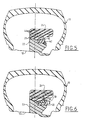
- the means for holding or blocking the second part radially outer 24 on the first piece radially internal 22 no longer include grooves and ribs complementary to their frustoconical surfaces, but a annular element 40 forming a corner, which is engaged to force between an external surface of the first part radially internal 22 and a frustoconical surface inside of the second radially outer part 24, the annular element 40 being maintained in an axial position on the first radially internal part 22 by a removable stop 42 such as an engaged split washer in a groove in the outer surface of the first radially internal part 22.
- the surface interior of the second radially outer part 24 is biconical in shape, its diameter increasing from the middle of this room inwards and towards outside of the tire, a first conical part of this interior surface cooperating with a surface conical complementary to the annular element 40, the other conical part of this inner surface cooperating with a conical surface complementary to the first part radially internal 22.
- the second radially external annular part 24 comprises, in addition as soon as covered with inextensible cords 28, strips 44 of inextensible material which are radially outside of the cable plies 28, so to avoid any risk of deformation of the part radially external 24 in use.
- the annular element 40 can form a ring continuous or be open at at least one point in its periphery. In the first case, it must be mounted on a frustoconical surface of the first piece radially internal 22 to tighten it on the rim when it is pushed between the two pieces. In the second case, it can be mounted on a cylindrical surface of the first radially internal part, as shown in FIG. 5.
- the fitting of the second radially external part 24 on the first and its locking in position are ensured by an open annular element 46 forming a corner, carried by an annular ring 48 split radially and having a threaded internal cylindrical surface for able to be screwed onto an external cylindrical surface corresponding thread of the first annular part radially internal 22.
- Pawns 50 are provided on the crown 48 to facilitate its rotation training around its axis and its screwing on the first part radially internal 22.
- Interlocking and maintaining or blocking the second radially external part 24 on the first radially internal part 22 are therefore provided by screwing the crown 48 onto the first annular part radially internal 22.
- the socket and the holding the second annular piece radially external 24 on the first annular piece radially internal 22 are provided by means of an annular element 40 similar to that shown in FIG. 5, but which has holes 52 parallel to its axis for the receiving bolts 54 screwed into nuts 56 mounted in corresponding holes in the first room radially internal 22 or embedded in the material constituting it.
- the inner surface of the second radially outer part 24 is biconical as already described and cooperates with an external surface conical of the annular element 40 and a surface conical exterior of opposite inclination formed on the first radially internal annular part 22. In these conditions, screwing the bolts 54 into the nuts 56 ensures the force fit and maintenance of the second radially external annular part 24 on the first radially internal annular part 22.
- the first radially annular piece internal 22 can be made in two semi-circular parts 22a and 22b as shown schematically in Figure 8, which facilitates their mounting on the rim 12, these two semi-circular parts 22a, 22b being able be easily maintained applied to the rim 12, until the bolts 54 are screwed in, using an O-ring 58 rubber mounted in a surface groove outer peripheral of these semicircular parts 22a, 22b.
- the annular element 40 or 48 can be locked by snap-fastening on the peripheral surface outside of the first radially internal part 22.
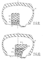
- Figures 9 and 10 show two alternative embodiments of the device according to the invention, in which a shaped intermediate piece 60 open ring, in relatively rigid material, by example the same as that of the first annular part radially internal 22, is interposed between this first radially internal part 22 and the second radially external annular part 24, which allows by example of halving the radial height of the first radially internal annular part 22 and therefore to facilitate its installation on the rim 12.
- the outer surface of the first part 22, the surfaces inside and outside of the intermediate piece 60 and the inner surface of the second annular part radially external 24 are frustoconical and are formed with grooves and ribs of the aforementioned type ensuring the holding in place, after fitting, of the part intermediate ring 60 on the first part radially internal annular 22 and of the second part radially external annular 24 on the annular part intermediate 60.
- the second radially annular piece external 24 ensures the clamping of the intermediate piece 60 on the first radially internal part 22, as well as tightening the first radially internal part 22 on rim 12.
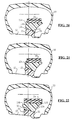
- FIG. 10 differs from that of figure 9 by the number and the form circumferential holding grooves and ribs of the three annular parts one on the other and in this that the second radially outer annular part 24 comprises, as already described, a lateral flange 34 oriented towards the outer side of the tire 10.
- the first radially internal annular part 22, thus that the intermediate annular part 60 can be made in two or more arcuate curved parts of circle, to facilitate their mounting around the rim, these parts being easily held in place one after the other by means of an O-ring or analog housed in a groove in their peripheral surface exterior, as already described for the embodiment Figures 7 and 8.
- the first radially annular piece internal 22 and intermediate piece 60 can also be made in several parts connected end to end by elements clipped to be held on the rim until the second piece is mounted radially external 24. They can also be formed of a ring continuous open at a point on its periphery but comprising several deformable zones (2, 3 or more) allowing their arrangement around the rim. This allows in particular to produce parts ribbed, lighter, of plastic material having a high modulus of elasticity. In this case, the second radially outer annular piece 24 of rubber can have a large internal diameter and a thickness relatively weak radial.
- a layer of rubber or the like between the rim and the internal surface of the first part, in order to catch up or compensate for manufacturing tolerances, compensate any irregularities in the rim surface (e.g. veil weld points) and increase the coefficient of friction between the rim and the run-flat device.
- Figures 11 to 15 schematically represent a preferred mode of production of a run-flat device according to the invention, intended to be mounted on a wheel standard type motor vehicle, including rim 12 is non-removable one-piece and has edges side 16 for supporting and holding the heels 18 of a pneumatic 10 of the tubeless type.
- the rim 12 of the wheel is formed with an annular recess or rim groove 14 and with two circumferential ribs 120 of retaining the beads 18 of the tire, the rib 120 located on the outside of the wheel (the right side on Figures 11 to 15) protruding further inside the tire than the other rib 120 located on the inner side of the wheel, the outer side of the tire being subjected to greater forces in bend as the inner side of the tire.
- the improved variant of the run flat according to the invention comprises a part radially internal 22 made of relatively rigid material, such as plastic, an annular piece intermediate 124 in relatively rigid material such as than a plastic, and an annular piece radially external 24 substantially inextensible, the first two annular parts 22, 124 being open at least one point on their periphery, while the radially external annular part 24 is continuous.
- the radially internal annular part 22 is placed on rim 12, partly inside of the rim groove 14 and has a shape combined with that of the rim 12 to be immobilized in translation in a direction parallel to the wheel axis and to stop in the outside-inside direction of the wheel.
- the room intermediate ring 124 is mounted on the workpiece radially internal annular 22, the annular surfaces opposite parts 22 and 124 having shapes frustoconical conjugates and comprising one at least one annular groove 30 and the other at least one rib annular 32 having corresponding shapes, allowing to mount the intermediate annular part 124 on the radially internal part by interlocking and snap-fit, the rib 32 of the intermediate piece 124 being housed in the groove 30 of the piece radially internal 22 and ensuring axial positioning and holding the intermediate piece 124 in the axial position on the radially internal part 22.
- the outer peripheral surface of the room intermediate 124 is formed with a groove or groove 132 in U in which the annular part is housed radially external 24, this groove or groove 132 having a side face of the inner side of the wheel which is higher than its side on the outside of the wheel, which facilitates the assembly and disassembly of the radially outer annular part on the part intermediate annular 124 as will be seen below, and which also improves the axial support of the radially external part 24 on the part intermediate 124 in the event of efforts applied to the run-flat device from outside to inside the tire.
- the bottom of the throat 132 is substantially parallel to the axis of the part 124.
- the radially outer annular part 24 is of substantially rectangular section and comprises at least a layer of cords 28 which are substantially inextensible, made for example of polyester, fiberglass, "KEVLAR TM" fibers, of metal, etc ... which form neighboring or substantially contiguous turns inside a mass of rubber or any suitable material having a relatively low modulus of elasticity, a annular part 24 such as that shown in figure 11 which can be carried out by implementing methods conventional transmission belt manufacturing power, with fairly good dimensional accuracy.
- the device run flat is offset from the median plane equatorial 136 of the wheel and is more on the side from the outer side of the tire 10, the annular part intermediate 124 also having a lateral rim 34 oriented towards the outer side of the tire and forming stop for this sidewall when running flat or with a partially deflated tire, to avoid the tire.
- the annular parts 22, 124 are advantageously made of a plastic material polyamide type such as "NYRIM". Exhibits 22, 124 can be massive or ribbed to reduce their weight.
- the radial thickness of the part 24 is for example of the order of 20 mm.
- the wheel is placed at flat with its outer side on top, the piece radially internal annular 22 being in place around the rim, the intermediate annular part 124 being partially engaged on the radially internal part and the radially outer annular part 24 being in place on the intermediate piece 124.
- the outer heel 18 of the pneumatic is pushed into the inside of the throat rim 14 and, at a point on the periphery of the wheel, we introduces a tire lever 144 inside the rim groove, so that the end of this lever is inside the rim groove and that a intermediate part of the lever is supported on the side outside of the tire, at the side rim 34 of the intermediate piece 124.
- the angle at the top of the frustoconical surfaces conjugates of the radially internal part 22 and the intermediate piece 124 is relatively small, for example from 30 to 50 ° approximately, so that the effort for fitting the intermediate piece 124 onto the piece radially internal 22 is not very important.
- the effort that must be applied to the intermediate piece 124 to disengage from the radially internal part 22 is not very important, thanks to the rounded shapes cooperating external lateral faces of the groove 30 and rib 32 above, but is clearly sufficient for the individual parts to remain held in place during use.
- the internal diameter of the annular part radially external 24 is determined to maintain the parts 22 and 124 clamped one on the other and on the rim 12 respectively by resisting the forces of rolling, when this radially external part 24 is in place on the intermediate piece 124.
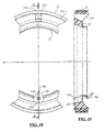
- the radially internal annular part 22 can be immobilized in rotation on the rim 12 by the valve 146 for inflating the tire (FIGS. 18 and 19) when this valve is metallic, the radially internal part 22 being placed on the rim so that the valve inflation 146 extends between its ends 148.
- the opening formed between the ends 150 of the intermediate annular part 124 is diametrically opposite the inflation valve 146.
- the annular part intermediate 124 includes a local rib 152 in protruding from its internal surface, this rib being diametrically opposite the ends 150 of the part intermediate 124 so as to be engaged between the ends 148 of the radially internal part 22 and at immobilize in rotation the intermediate piece 124 on the radially internal part 22.
- the ends 150 of the intermediate piece 124 are separated from each other in the free state of one. distance which is at least equal to or greater than the difference between the external peripheral dimension of the intermediate piece 124 and the peripheral dimension internal of the radially external part 24 so that that when these ends 150 are brought together one of the other, the external peripheral dimension of the part intermediate 124 becomes equal or slightly lower to the internal peripheral dimension of the part radially external 24.
- the distance between the ends 148 of the radially internal annular part 22 is determined to allow a good balance in rotation of the run-flat device when the openings of the annular parts 22 and 124 are diametrically opposed to each other as shown schematically in Figures 18 and 19.
- the run-flat device differs from that of the preceding figures by the configuration of the frustoconical conjugate surfaces of the part radially internal 22 and intermediate piece 124.
- the frustoconical peripheral surface of the radially internal part 22 is formed with a groove 30 with rounded section on the side of its outer flank and with a radial rim 154 on its inner flank, the internal peripheral surface of the intermediate piece 124 being of complementary shape and therefore comprising a rib 32 with curved section in the vicinity of its side outside, and a recess 156 on its side inside.
- This configuration reduces the effort for fitting the intermediate piece 124 onto the piece radially internal 22.
- the frustoconical surfaces of parts 22 and 124 are each formed with a groove and a rib, the groove formed in the outer peripheral surface of the radially internal part 22 receiving the rib formed on the inner peripheral surface of the part intermediate 124, while the rib formed on the outer peripheral surface of the part radially internal 22 engages in the groove formed in the inner peripheral surface of the intermediate piece 124.
- the groove 30 formed in the surface radially internal external peripheral of the part 22 and the rib 32 formed in the peripheral surface interior of intermediate piece 124 are more closer to the inner sides of these parts than in the embodiment of FIGS. 11 to 15, and the side interior of the intermediate piece 124 is formed with a annular boss 158 forming a bearing surface on which one will come to exert a push as represented schematically by the arrows 142 in FIG. 15, for the disassembly of the run-flat device according to the invention.
- the groove 132 formed in the surface outer peripheral of the intermediate piece 124 a side walls which diverge from each other towards the outside, the inner peripheral surface of the radially outer part 24 being shaped which makes it easier to catch up manufacturing tolerances when mounting the part radially outer 24 on the workpiece intermediate 124.
- the outer peripheral surface of the part radially internal 22 is formed, in the vicinity of its. inner flank, with a rounded section rib which engages in a groove of complementary shape to the inner peripheral surface of the intermediate piece 124, and includes on its outer flank a recess annular in which engages a peripheral rim radial of the inner flank of the intermediate piece 124.
- annular piece radially outer 24 is formed by two layers of material having different hardnesses, an outer layer 160 of greater hardness containing inextensible cords 38 and an inner layer 162 of lower hardness, which is engaged in the groove of the peripheral surface outside of the intermediate piece 124 and the lower hardness better compensates for manufacturing tolerances.
- the run-flat device differs from precedent basically in that the annular piece radially external 24 is no longer section rectangular, but has a peripheral surface internal of frustoconical shape which is housed in a groove in the outer peripheral surface of the part intermediate 124, the bottom of this groove forming also a frustoconical surface relative to the axis of the intermediate piece 124, the frustoconical surfaces mentioned above widening from the outside towards inside the wheel.
- This configuration facilitates the mounting of the radially external part 24 on the intermediate part 124, but increases the volume and mass of the room radially outer annular 24.
- locking and unlocking of the intermediate annular part on the first can be done with any tool or any machine for applying localized pressure or circumferential on the sidewall of the tire.
Landscapes
- Engineering & Computer Science (AREA)
- Mechanical Engineering (AREA)
- Tires In General (AREA)
- Support Of The Bearing (AREA)
Description
- la figure 1 est une demi-vue schématique en coupe axiale représentant un dispositif selon l'invention monté sur une jante à l'intérieur d'un pneumatique ;
- les figures 2 et 3 sont des vues semblables à la figure 1 et illustrent des phases de montage du dispositif selon l'invention ;
- les figures 4 à 7 représentent schématiquement des variantes de réalisation ;
- la figure 8 est une vue schématique en coupe partielle selon la ligne VIII de la figure 7 ;
- les figures 9 et 10 représentent schématiquement d'autres variantes de réalisation de l'invention ;
- la figure 11 est une vue schématique partielle en coupe axiale d'une roue de véhicule automobile, équipée d'une variante perfectionnée préférée d'un dispositif de roulage à plat selon l'invention ;
- les figures 12 à 15 sont des vues schématiques illustrant le montage d'une variante perfectionnée et le démontage de ce dispositif ;
- les figures 16 et 17 illustrent schématiquement un mode de montage d'une variante perfectionnée d'un dispositif selon l'invention sur une jante de roue ;
- la figure 18 est une vue schématique partielle de face d'un dispositif de roulage à plat selon l'invention ;
- la figure 19 est une vue schématique en coupe axiale selon la ligne A-A de la figure 18 ;
- les figures 20 à 24 sont des vues correspondant à la figure 10 et représentent diverses variantes de réalisation de l'invention ;
- la figure 25 est une vue schématique partielle en coupe axiale d'une variante de réalisation de la pièce intermédiaire annulaire du dispositif selon l'invention.
Claims (35)
- Dispositif de roulage à plat pour véhicule automobile, destiné à être monté serré sur une jante standard (12) à rebords latéraux (16) de maintien des talons (18) d'un pneumatique, caractérisé en ce qu'il est constitué d'au moins deux pièces annulaires coaxiales (22, 24) emboítées l'une sur l'autre, la pièce radialement interne étant en matière relativement rigide et formant un anneau ouvert autour de la jante, la pièce radialement externe étant à base de matière élastiquement déformable et comprenant un anneau continu d'une seule pièce entourant la pièce annulaire radialement interne (22) et ayant un diamètre interne sensiblement égal ou supérieur au diamètre extérieur d'un rebord latéral (16) de la jante.
- Dispositif selon la revendication 1, caractérisé en ce que la pièce radialement externe (24) a un diamètre interne légèrement inférieur au diamètre externe de la pièce annulaire radialement interne (22) et est emboítée à force sur celle-ci.
- Dispositif selon la revendication 1 ou 2, caractérisé en ce que la pièce annulaire radialement externe (24) comprend des moyens annulaires (28, 44) sensiblement inextensibles, par exemple noyés dans la matière constitutive de la pièce radialement externe.
- Dispositif selon l'une des revendications précédentes, caractérisé en ce que les surfaces de contact entre les deux pièces coaxiales (22, 24) sont, au moins en partie, tronconiques.
- Dispositif selon l'une des revendications précédentes, caractérisé en ce qu'il comprend des moyens de maintien axial de la pièce radialement externe (24) sur la pièce radialement interne.
- Dispositif selon la revendication 5, caractérisé en ce que les moyens de maintien axial comprennent un élément annulaire (40, 46, 48) formant coin entre la pièce radialement interne et la pièce radialement externe et maintenu en position entre ces deux pièces par des moyens de fixation ou de blocage.
- Dispositif selon la revendication 6, caractérisé en ce que les moyens de fixation comprennent des vis (54) parallèles à l'axe de la jante et engagées dans des trous correspondants de l'élément annulaire (40) et de la pièce radialement interne (22).
- Dispositif selon la revendication 7, caractérisé en ce que les vis sont vissées dans des écrous (56) logés dans les trous précités de la pièce radialement interne ou noyés dans la matière constitutive de celle-ci.
- Dispositif selon la revendication 6, caractérisé en ce que l'élément annulaire (48) comprend une surface interne cylindrique filetée et est vissé sur une portée cylindrique filetée correspondante de la pièce radialement interne (22).
- Dispositif selon la revendication 6, caractérisé en ce que l'élément annulaire (40) est maintenu en position sur la pièce.radialement interne par encliquetage ou au moyen d'une rondelle fendue (42) logée dans une gorge d'une surface périphérique de la pièce radialement interne (22).
- Dispositif selon la revendication 5, caractérisé en ce que les moyens de maintien axial de la pièce radialement externe (24) sur la pièce radialement interne comprennent des rainures et nervures circonférentielles (30, 32) formées dans des surfaces de contact entre la pièce radialement interne et la pièce annulaire radialement externe.
- Dispositif selon l'une des revendications précédentes, caractérisé en ce qu'il comporte une pièce annulaire intermédiaire coaxiale ouverte (60, 124) emboítée entre lesdites pièces radialement interne (22) et radialement externe (24).
- Dispositif selon la revendication 12, caractérisé en ce que les surfaces de contact les pièces radialement interne (22) et la pièce annulaire intermédiaire sont, au moins en partie, tronconiques.
- Dispositif selon la revendication 12 ou 13, caractérisé en ce qu'il comprend des moyens de maincien axial l'une sur l'autre des pièces (22, 60) radialement interne et intermédiaire, ces moyens étant tels par exemple que des rainures et nervures circonférentielles formées dans les surfaces de contact entre ces deux pièces.
- Dispositif selon l'une des revendications précédentes, caractérisé en ce que la pièce annulaire radialement interne et/ou la pièce intermédiaire (22, 60) sont en matière plastique rigide et la pièce annulaire radialement externe (24) est à base de caoutchouc ou d'élastomère.
- Dispositif selon l'une des revendications précédentes, caractérisé en ce que la pièce annulaire radialement interne (22) est formée d'au moins deux parties (22a, 22b) incurvées en arc de cercle, placées bout à bout autour de la jante (12).
- Dispositif selon la revendication 16,
caractérisé en ce que les parties précitées (22a, 22b) de la pièce annulaire radialement interne sont maintenues sur la jante par un joint torique (58) ou analogue, logé dans une gorge de la surface extérieure desdites parties (22a, 22b). - Dispositif selon l'une des revendications précédentes, caractérisé en ce qu'une couche de caoutchouc ou analogue est interposée entre la jante (12) et la pièce annulaire radialement interne (22).
- Dispositif de roulage à plat pour véhicule automobile, selon l'une des revendications 12 à 18 et comprenant au moins une pièce annulaire ouverte radialement interne (22) et une pièce annulaire ouverte intermédiaire (124) en matière relativement rigide et destinées à être montées l'un sur l'autre autour de la jante de la roue, et une pièce annulaire radialement externe continue (24) sensiblement inextensible et destinée à être montée sur la pièce annulaire ouverte intermédiaire (124), caractérisé en ce que la surface périphérique externe de la pièce annulaire intermédiaire (124) est formée avec une gorge ou rainure circonférentielle (132) de réception de la pièce annulaire radialement externe (24), cette gorge ou rainure (132) étant à section transversale sensiblement en U.
- Dispositif selon une quelconque des revendications 12 à 19 et comprenant au moins une pièce annulaire ouverte intermédiaire (24), caractérisé en ce que la surface périphérique radialement externe de la pièce annulaire intermédiaire (124) est sensiblement parallèle à l'axe de cette pièce.
- Dispositif selon l'une quelconque des revendications 1 à 20, caractérisé en ce que la pièce annulaire radialement externe (24) est à section sensiblement rectangulaire.
- Dispositif selon l'une quelconque des des revendications 1 à 21, caractérisé en ce que la pièce annulaire radialement externe (24) comprend des éléments inextensibles tels que des spires de câblés (28), noyés dans une matière du type caoutchouc.
- Dispositif selon la revendication 22, caractérisé en ce que la pièce annulaire radialement externe (24) comprend deux couches (160, 162) de caoutchouc de duretés différentes.
- Dispositif selon l'une quelconque des des revendications 1 à 23, caractérisé en ce que la pièce annulaire radialement externe (24) est réversible.
- Dispositif selon l'une des revendications 12 à 24 et comprenant au moins une pièce annulaire ouverte intermédiaire (24), caractérisé en ce que les surfaces en contact de la pièce annulaire radialement interne (22) et de la pièce annulaire intermédiaire (124) sont sensiblement tronconiques, avec un angle au sommet de l'ordre de 30 à 50°.
- Dispositif selon la revendication 25, caractérisé en ce que les surfaces en contact de la pièce annulaire radialement interne (22) et de la pièce annulaire intermédiaire (124) sont formées, l'une avec au moins une rainure circonférentielle (30) et l'autre avec au moins une nervure circonférentielle (32) ayant des formes conjuguées et destinées à s'emboíter l'une dans l'autre, cette rainure (30) et cette nervure (32) ayant en section transversale une forme dissymétrique avec un côté extérieur oblique ou arrondi permettant de réduire les efforts de montage et de démontage de ces deux pièces l'une sur l'autre.
- Dispositif selon l'une quelconque des des revendications 12 à 26 et comprenant au moins une pièce annulaire ouverte intermédiaire (24), caractérisé en ce que la distance entre des extrémités (150) de la pièce annulaire intermédiaire (124) à l'état libre est au moins égale à la différence entre la dimension périphérique externe de cette pièce annulaire intermédiaire (124) à l'état libre et la dimension périphérique interne de la pièce annulaire radialement externe (24).
- Dispositif selon l'une quelconque des des revendications 12 à 27 et comprenant au moins une pièce annulaire ouverte intermédiaire (24), caractérisé en ce que la pièce annulaire radialement interne (22) et la pièce annulaire. intermédiaire (124) sont disposées angulairement l'une par rapport à l'autre de telle sorte que leurs ouvertures sont diamétralement opposées et que la valve de gonflage (146) montée sur la jante (12) passe dans l'ouverture de la pièce annulaire radialement interne (22).
- Dispositif selon l'une quelconque des des revendications 12 à 28 et comprenant au moins un pièce annulaire ouverte intermédiaire (24), caractérisé en ce que la surface périphérique interne de la pièce intermédiaire (124) comporte une nervure ou saillie locale (152) destinée à être logée dans l'ouverture de la pièce annulaire radialement interne (22) pour immobiliser en rotation la pièce annulaire intermédiaire (124) sur la pièce annulaire radialement interne (22).
- Dispositif selon l'une quelconque des des revendications 12 à 29 et comprenant au moins une pièce annulaire ouverte intermédiaire (24), caractérisé en ce qu'un flanc de la pièce annulaire intermédiaire (124) comprend un bossage annulaire (158) en saillie, formant surface d'appui pour le démontage du dispositif.
- Dispositif selon l'une quelconque des des revendications 12 à 30 et comprenant au moins un pièce annulaire ouverte intermédiaire (24), caractérisé en ce que le fond de la gorge (132) formée dans la surface périphérique radialement externe de la pièce annulaire intermédiaire (124) pour la réception de la pièce annulaire radialement externe (24) est ondulé.
- Procédé de montage d'un dispositif de roulage à plat sur une roue de véhicule automobile, caractérisé en ce que ce dispositif comprend au moins une pièce annulaire radialement interne (22) et une pièce annulaire intermédiaire (124) en matière relativement rigide, ouvertes en au moins un point de leur périphérie et destinées à être montées l'une sur l'autre autour de la jante (12) de la roue, et une pièce annulaire radialement externe (24) continue et coaxiale aux deux précédentes, cette pièce radialement externe étant sensiblement inextensible et ayant un diamètre intérieur supérieur au diamètre extérieur du rebord (16) de la jante, et en ce qu'il consiste à monter la pièce annulaire ouverte radialement interne (22) sur la jante (12), cette pièce radialement interne étant bloquée sur la jante (12) en translation axiale, à introduire la pièce annulaire intermédiaire (124) à l'intérieur du pneumatique (10) et à la placer autour de la jante (12) au voisinage de la pièce annulaire radialement interne (22), à introduire la pièce annulaire radialement externe (24) à l'intérieur du pneumatique et à la monter sur la pièce annulaire intermédiaire (124), puis à pousser l'ensemble formé par les pièces annulaires intermédiaire et radialement externe (124, 24) sur la pièce annulaire radialement interne (22) jusqu'à encliquetage, les surfaces annulaires en regard des pièces annulaires radialement interne et intermédiaire (22, 124) ayant des formes conjuguées, notamment sensiblement tronconiques, avec des moyens tels que des nervures (32) et des rainures (28) de formes conjuguées, ces surfaces annulaires coopérant entre elles pour assurer à la fois le serrage de la pièce radialement interne (22) sur la jante (12) et le positionnement axial et le blocage en position de la pièce annulaire intermédiaire (124) sur la pièce radialement interne (22).
- Procédé selon la revendication 32, caractérisé en ce que la pièce annulaire radialement externe (24) ayant un diamètre interne inférieur au diamètre externe de la pièce annulaire intermédiaire (124) à l'état libre, il consiste à resserrer la pièce annulaire intermédiaire (124) en rapprochant ses extrémités l'une de l'autre avant de monter la pièce annulaire radialement externe (24) sur la pièce intermédiaire, autour de la jante (12).
- Procédé de démontage d'un dispositif de roulage à plat monté sur une roue par exécution du procédé selon la revendication 32 ou 33, caractérisé en ce qu'il consiste à pousser sur la pièce annulaire intermédiaire (124) dans une direction opposée à la direction de poussée au montage, pour dégager de la pièce annulaire radialement interne (22) l'ensemble formé par les pièces annulaires intermédiaire et radialement externe (124, 24), puis à resserrer sur elle-même la pièce annulaire intermédiaire (124), à dégager la pièce annulaire radialement externe (24) de la pièce intermédiaire (124) et à la sortir de la jante (12), puis à sortir successivement de la jante la pièce annulaire intermédiaire et la pièce annulaire radialement interne (124, 22).
- Procédé selon l'une des revendications 32 à 34, caractérisé en ce que pour le montage et le démontage du dispositif de roulage à plat, le talon extérieur (18) du pneumatique (10) est dégagé du rebord (16) de la jante, pour permettre l'introduction des trois pièces annulaires (22, 124, 24) à l'intérieur du pneumatique et leur disposition autour de la jante (12).
Applications Claiming Priority (5)
| Application Number | Priority Date | Filing Date | Title |
|---|---|---|---|
| FR9713618 | 1997-10-30 | ||
| FR9713618A FR2770459B1 (fr) | 1997-10-30 | 1997-10-30 | Dispositif de roulage a plat pour vehicule automobile |
| FR9804225A FR2776963B1 (fr) | 1998-04-06 | 1998-04-06 | Dispositif de roulage a plat pour vehicule automobile et son procede de montage |
| FR9804225 | 1998-04-06 | ||
| PCT/FR1998/002330 WO1999022953A1 (fr) | 1997-10-30 | 1998-10-30 | Dispositif de roulage a plat pour vehicule automobile et son procede de montage |
Publications (2)
| Publication Number | Publication Date |
|---|---|
| EP0956212A1 EP0956212A1 (fr) | 1999-11-17 |
| EP0956212B1 true EP0956212B1 (fr) | 2002-05-08 |
Family
ID=26233906
Family Applications (1)
| Application Number | Title | Priority Date | Filing Date |
|---|---|---|---|
| EP98952826A Expired - Lifetime EP0956212B1 (fr) | 1997-10-30 | 1998-10-30 | Dispositif de roulage a plat pour vehicule automobile et son procede de montage |
Country Status (6)
| Country | Link |
|---|---|
| US (1) | US6286574B1 (fr) |
| EP (1) | EP0956212B1 (fr) |
| CA (1) | CA2276710A1 (fr) |
| DE (1) | DE69805277T2 (fr) |
| ES (1) | ES2177077T3 (fr) |
| WO (1) | WO1999022953A1 (fr) |
Families Citing this family (16)
| Publication number | Priority date | Publication date | Assignee | Title |
|---|---|---|---|---|
| DE10001269B4 (de) * | 2000-01-14 | 2006-08-31 | Daimlerchrysler Ag | Fahrzeugrad für einen schlauchlosen Luftreifen |
| DE10011673C2 (de) * | 2000-03-10 | 2003-02-20 | Continental Ag | Fahrzeugrad mit Felge und schlauchlosem Luftreifen und mit ringförmigen Notlaufstützkörper |
| DE10011647C2 (de) * | 2000-03-10 | 2003-02-20 | Continental Ag | Fahrzeugrad mit Felge und schlauchlosem Luftreifen und mit ringförmigen Notlaufstützkörper |
| US6360800B1 (en) * | 2000-06-05 | 2002-03-26 | Hutchinson Sa | Runflat wheel for tubeless tire |
| IT1319474B1 (it) * | 2000-06-23 | 2003-10-10 | Corghi Spa | Dispositivo per operare su pneumatici del tipo system pax e simili |
| KR100835873B1 (ko) * | 2000-09-11 | 2008-06-09 | 다우 글로벌 테크놀로지스 인크. | 무공압 주행 타이어 지지부 및 그를 위한 착색제 |
| FR2814118B1 (fr) * | 2000-09-21 | 2003-01-24 | Michelin Soc Tech | Appui de soutien de bande de roulement |
| FR2841825B1 (fr) * | 2002-07-08 | 2004-08-27 | Michelin Soc Tech | Jante de roue constituee de deux structures assemblees |
| US7400469B2 (en) * | 2003-09-16 | 2008-07-15 | Spectra Logic Corporation | Magazine-based library |
| US20050051249A1 (en) * | 2003-09-05 | 2005-03-10 | Lee Gul Nam | Run-flat tire |
| JP4382562B2 (ja) * | 2004-04-12 | 2009-12-16 | 株式会社ブリヂストン | ランフラットタイヤのランフラット走行寿命末期を判定する方法及び装置 |
| US20080307691A1 (en) * | 2004-07-26 | 2008-12-18 | Halldor Egill Guonason | High Speed, Increased Hydrodynamic Efficiency, Light-Weight Molded Trawl Door and Methods for Use and Manufacture |
| US20060162834A1 (en) * | 2005-01-25 | 2006-07-27 | Chen Yueh N | Vehicle wheel rim assembly |
| CN101982324A (zh) * | 2010-10-21 | 2011-03-02 | 黄强 | 带化险减损环的汽车车轮 |
| CA3071943A1 (fr) * | 2017-08-03 | 2019-02-07 | Hutchinson Industries, Inc. | Systeme de roulage a plat comprenant un element de capuchon elastomere continu |
| IT202200026691A1 (it) * | 2022-12-23 | 2024-06-23 | Giuliano Group Spa | Macchina per l’inserimento/estrazione di toroidi in/da ruote di veicoli speciali |
Family Cites Families (18)
| Publication number | Priority date | Publication date | Assignee | Title |
|---|---|---|---|---|
| US1343685A (en) * | 1919-02-01 | 1920-06-15 | Arthur L Runyan | Resilient tire-filler |
| US2040645A (en) * | 1934-07-27 | 1936-05-12 | Fredrick S Dickinson | Noncollapsible tire |
| DE2319501A1 (de) * | 1973-04-17 | 1974-11-07 | Hans Wimmer | Fahrzeugluftreifen mit notlaufvorrichtung |
| US4374535A (en) * | 1975-09-30 | 1983-02-22 | The Goodyear Tire & Rubber Company | Wheel well filler |
| DE2658049A1 (de) * | 1976-12-22 | 1978-07-06 | Continental Gummi Werke Ag | Fahrzeugrad |
| JPS54122501A (en) * | 1978-03-14 | 1979-09-22 | Ohtsu Tire & Rubber Co Ltd | Safe wheel |
| US4183388A (en) * | 1978-07-24 | 1980-01-15 | General Motors Corporation | Run-flat tire having internal support means |
| FR2516868A1 (fr) * | 1981-11-20 | 1983-05-27 | Michelin & Cie | Support interne pour s'opposer a l'aplatissement d'un pneumatique |
| US4393911A (en) * | 1982-07-26 | 1983-07-19 | Astronics Corporation | Safety liner for tires |
| FR2555944B1 (fr) * | 1983-12-01 | 1986-07-18 | Michelin & Cie | Dispositif de blocage des bourrelets d'une enveloppe de pneumatique |
| US4722377A (en) * | 1984-06-11 | 1988-02-02 | The Goodyear Tire & Rubber Company | Tire safety support system |
| CA1237050A (fr) * | 1984-09-10 | 1988-05-24 | Bernard J. O'coin | Pneu increvable a carcasse reutilisable, et son montage |
| US4854356A (en) * | 1985-07-26 | 1989-08-08 | Theodore Koutsoupidis | Safety apparatus for tire |
| US4662419A (en) * | 1986-02-06 | 1987-05-05 | Astronics Corporation | Beadlock for tubeless tires |
| US5435363A (en) * | 1993-02-19 | 1995-07-25 | Pender; David R. | Run-flat pneumatic tires including plural separate inserts |
| FR2719258B1 (fr) * | 1994-04-27 | 1996-07-19 | Hutchinson | Dispositif de roulage à plat pour véhicule automobile. |
| US5479976A (en) * | 1994-12-20 | 1996-01-02 | Cho; Woon-Je | Three-chamber tire |
| FR2729105A1 (fr) * | 1995-01-05 | 1996-07-12 | Hutchinson | Dispositif de roulage a plat pour vehicule automobile et son procede de fabrication |
-
1998
- 1998-10-30 DE DE69805277T patent/DE69805277T2/de not_active Expired - Fee Related
- 1998-10-30 US US09/331,192 patent/US6286574B1/en not_active Expired - Fee Related
- 1998-10-30 ES ES98952826T patent/ES2177077T3/es not_active Expired - Lifetime
- 1998-10-30 WO PCT/FR1998/002330 patent/WO1999022953A1/fr not_active Ceased
- 1998-10-30 CA CA002276710A patent/CA2276710A1/fr not_active Abandoned
- 1998-10-30 EP EP98952826A patent/EP0956212B1/fr not_active Expired - Lifetime
Also Published As
| Publication number | Publication date |
|---|---|
| WO1999022953A1 (fr) | 1999-05-14 |
| CA2276710A1 (fr) | 1999-05-14 |
| EP0956212A1 (fr) | 1999-11-17 |
| DE69805277T2 (de) | 2003-02-06 |
| ES2177077T3 (es) | 2002-12-01 |
| DE69805277D1 (de) | 2002-06-13 |
| US6286574B1 (en) | 2001-09-11 |
Similar Documents
| Publication | Publication Date | Title |
|---|---|---|
| CA2276710A1 (fr) | Dispositif de roulage a plat pour vehicule automobile et son procede de montage | |
| EP0796747B1 (fr) | Appui de sécurité en matériau élastomérique souple pour pneumatique | |
| EP2316663B1 (fr) | Jante de roue à rayons, ensemble monté l'incorporant et son procédé d'assemblage | |
| CA2781829A1 (fr) | Roue composite, notamment pour un cycle, et procede de fabrication d'une telle roue | |
| EP0679544B1 (fr) | Dispositif de roulage à plat pour véhicule automobile | |
| CH626836A5 (en) | Assembly comprising a tread strip and a wheel rim | |
| EP0878328B1 (fr) | Pneumatique du type semi-creux et rouleau équipé de tels pneumatiques | |
| EP2139705A1 (fr) | Dispositif de roulage a plat pour vehicule automobile et ensemble monte l'incorporant | |
| EP0430743A1 (fr) | Dispositif d'anneau pour roulage à plat | |
| EP1420966B1 (fr) | Ensemble monte tubeless pour cycle | |
| FR2776963A1 (fr) | Dispositif de roulage a plat pour vehicule automobile et son procede de montage | |
| EP1868823B1 (fr) | Anneau de verrouillage dans un ensemble de montage d'un pneumatique sur un moyeu de vehicule | |
| EP1868824B1 (fr) | Systeme de verrouillage d'un anneau de montage sur un moyeu de vehicule | |
| EP0798141A1 (fr) | Dispositif de roulage à plat pour véhicule automobile et son procédé de montage | |
| CA2475417A1 (fr) | Methode pour alleger un dispositif de roulage a plat de roue de vehicule automobile et dispositif ainsi obtenu | |
| EP3727883A1 (fr) | Assemblage pour bandage | |
| FR2770459A1 (fr) | Dispositif de roulage a plat pour vehicule automobile | |
| FR2844479A1 (fr) | Roue de vehicule | |
| EP1538007B1 (fr) | Dispositif de roulage à plat pour véhicule automobile et ensemble monté l'incorporant | |
| FR2842140A1 (fr) | Ensemble monte tubeless pour cycle, jante et pneumatique tubeless | |
| EP1901928B1 (fr) | Jante de vehicule avec des sieges de diametres inegaux | |
| EP1190873A1 (fr) | Systeme de roulage a plat pour vehicule automobile | |
| EP1612063B1 (fr) | Dispositif de démontage d'un pneumatique sur jante à sièges inclines vers l'extérieur | |
| FR2843335A1 (fr) | Dispositif de securite pour les pneumatiques montes sur des jantes monobloc a gorge de montage. | |
| CA3252835A1 (fr) | Dispositif de roulement à plat |
Legal Events
| Date | Code | Title | Description |
|---|---|---|---|
| PUAI | Public reference made under article 153(3) epc to a published international application that has entered the european phase |
Free format text: ORIGINAL CODE: 0009012 |
|
| 17P | Request for examination filed |
Effective date: 19990629 |
|
| AK | Designated contracting states |
Kind code of ref document: A1 Designated state(s): DE ES FR GB IT NL SE |
|
| GRAG | Despatch of communication of intention to grant |
Free format text: ORIGINAL CODE: EPIDOS AGRA |
|
| 17Q | First examination report despatched |
Effective date: 20010827 |
|
| GRAG | Despatch of communication of intention to grant |
Free format text: ORIGINAL CODE: EPIDOS AGRA |
|
| GRAH | Despatch of communication of intention to grant a patent |
Free format text: ORIGINAL CODE: EPIDOS IGRA |
|
| REG | Reference to a national code |
Ref country code: GB Ref legal event code: IF02 |
|
| GRAH | Despatch of communication of intention to grant a patent |
Free format text: ORIGINAL CODE: EPIDOS IGRA |
|
| GRAA | (expected) grant |
Free format text: ORIGINAL CODE: 0009210 |
|
| AK | Designated contracting states |
Kind code of ref document: B1 Designated state(s): DE ES FR GB IT NL SE |
|
| REF | Corresponds to: |
Ref document number: 69805277 Country of ref document: DE Date of ref document: 20020613 |
|
| GBT | Gb: translation of ep patent filed (gb section 77(6)(a)/1977) |
Effective date: 20020812 |
|
| REG | Reference to a national code |
Ref country code: ES Ref legal event code: FG2A Ref document number: 2177077 Country of ref document: ES Kind code of ref document: T3 |
|
| PLBE | No opposition filed within time limit |
Free format text: ORIGINAL CODE: 0009261 |
|
| STAA | Information on the status of an ep patent application or granted ep patent |
Free format text: STATUS: NO OPPOSITION FILED WITHIN TIME LIMIT |
|
| 26N | No opposition filed |
Effective date: 20030211 |
|
| PGFP | Annual fee paid to national office [announced via postgrant information from national office to epo] |
Ref country code: FR Payment date: 20050830 Year of fee payment: 8 |
|
| PGFP | Annual fee paid to national office [announced via postgrant information from national office to epo] |
Ref country code: ES Payment date: 20050914 Year of fee payment: 8 |
|
| PGFP | Annual fee paid to national office [announced via postgrant information from national office to epo] |
Ref country code: GB Payment date: 20051004 Year of fee payment: 8 |
|
| PGFP | Annual fee paid to national office [announced via postgrant information from national office to epo] |
Ref country code: SE Payment date: 20051005 Year of fee payment: 8 |
|
| PGFP | Annual fee paid to national office [announced via postgrant information from national office to epo] |
Ref country code: NL Payment date: 20051028 Year of fee payment: 8 |
|
| PGFP | Annual fee paid to national office [announced via postgrant information from national office to epo] |
Ref country code: DE Payment date: 20051222 Year of fee payment: 8 |
|
| PG25 | Lapsed in a contracting state [announced via postgrant information from national office to epo] |
Ref country code: SE Free format text: LAPSE BECAUSE OF NON-PAYMENT OF DUE FEES Effective date: 20061031 |
|
| PGFP | Annual fee paid to national office [announced via postgrant information from national office to epo] |
Ref country code: IT Payment date: 20061031 Year of fee payment: 9 |
|
| PG25 | Lapsed in a contracting state [announced via postgrant information from national office to epo] |
Ref country code: NL Free format text: LAPSE BECAUSE OF NON-PAYMENT OF DUE FEES Effective date: 20070501 Ref country code: DE Free format text: LAPSE BECAUSE OF NON-PAYMENT OF DUE FEES Effective date: 20070501 |
|
| EUG | Se: european patent has lapsed | ||
| GBPC | Gb: european patent ceased through non-payment of renewal fee |
Effective date: 20061030 |
|
| NLV4 | Nl: lapsed or anulled due to non-payment of the annual fee |
Effective date: 20070501 |
|
| REG | Reference to a national code |
Ref country code: FR Ref legal event code: ST Effective date: 20070629 |
|
| PG25 | Lapsed in a contracting state [announced via postgrant information from national office to epo] |
Ref country code: GB Free format text: LAPSE BECAUSE OF NON-PAYMENT OF DUE FEES Effective date: 20061030 |
|
| REG | Reference to a national code |
Ref country code: ES Ref legal event code: FD2A Effective date: 20061031 |
|
| PG25 | Lapsed in a contracting state [announced via postgrant information from national office to epo] |
Ref country code: FR Free format text: LAPSE BECAUSE OF NON-PAYMENT OF DUE FEES Effective date: 20061031 Ref country code: ES Free format text: LAPSE BECAUSE OF NON-PAYMENT OF DUE FEES Effective date: 20061031 |
|
| PG25 | Lapsed in a contracting state [announced via postgrant information from national office to epo] |
Ref country code: IT Free format text: LAPSE BECAUSE OF NON-PAYMENT OF DUE FEES Effective date: 20071030 |