EP0956212B1 - Notlaufvorrichtung für auto und verfahren zu seiner montage - Google Patents
Notlaufvorrichtung für auto und verfahren zu seiner montage Download PDFInfo
- Publication number
- EP0956212B1 EP0956212B1 EP98952826A EP98952826A EP0956212B1 EP 0956212 B1 EP0956212 B1 EP 0956212B1 EP 98952826 A EP98952826 A EP 98952826A EP 98952826 A EP98952826 A EP 98952826A EP 0956212 B1 EP0956212 B1 EP 0956212B1
- Authority
- EP
- European Patent Office
- Prior art keywords
- radially
- piece
- annular piece
- annular
- rim
- Prior art date
- Legal status (The legal status is an assumption and is not a legal conclusion. Google has not performed a legal analysis and makes no representation as to the accuracy of the status listed.)
- Expired - Lifetime
Links
Images


Classifications
-
- B—PERFORMING OPERATIONS; TRANSPORTING
- B60—VEHICLES IN GENERAL
- B60C—VEHICLE TYRES; TYRE INFLATION; TYRE CHANGING; CONNECTING VALVES TO INFLATABLE ELASTIC BODIES IN GENERAL; DEVICES OR ARRANGEMENTS RELATED TO TYRES
- B60C17/00—Tyres characterised by means enabling restricted operation in damaged or deflated condition; Accessories therefor
- B60C17/04—Tyres characterised by means enabling restricted operation in damaged or deflated condition; Accessories therefor utilising additional non-inflatable supports which become load-supporting in emergency
- B60C17/06—Tyres characterised by means enabling restricted operation in damaged or deflated condition; Accessories therefor utilising additional non-inflatable supports which become load-supporting in emergency resilient
-
- B—PERFORMING OPERATIONS; TRANSPORTING
- B60—VEHICLES IN GENERAL
- B60C—VEHICLE TYRES; TYRE INFLATION; TYRE CHANGING; CONNECTING VALVES TO INFLATABLE ELASTIC BODIES IN GENERAL; DEVICES OR ARRANGEMENTS RELATED TO TYRES
- B60C17/00—Tyres characterised by means enabling restricted operation in damaged or deflated condition; Accessories therefor
- B60C17/04—Tyres characterised by means enabling restricted operation in damaged or deflated condition; Accessories therefor utilising additional non-inflatable supports which become load-supporting in emergency
- B60C17/06—Tyres characterised by means enabling restricted operation in damaged or deflated condition; Accessories therefor utilising additional non-inflatable supports which become load-supporting in emergency resilient
- B60C2017/068—Tyres characterised by means enabling restricted operation in damaged or deflated condition; Accessories therefor utilising additional non-inflatable supports which become load-supporting in emergency resilient comprising springs, e.g. helical springs
Definitions
- the invention relates to a device for flat running for a motor vehicle, enabling cover a significant distance (at least 100 km) at relatively high speed (at least 80 km / h) with a partially or fully deflated tire, as well that a method of mounting this device.
- Known devices of this type can have a relatively simple structure when they are intended for removable rims or rims but, when they must be mounted on standard rims (in one piece) with side flanges fixed heels of a tire, they are necessarily in several parts each having the shape of a circular arc, which are connected end to end by mechanical means of screw connection, to eccentric, etc ... to form a rolling ring that can be tightened on the rim and can be removed and remove from the rim despite the side edges of it.
- a run-flat device comprising the characteristics of the preamble of the Claim 1 is known from EP-A-0 679 544.
- connecting and clamping means are the cause significant disadvantages because their handling is inconvenient and sometimes long (you have to pass the hands and / or tools between the rim and the tire) and it can be critical because a bad tightening of the rolling ring on the rim can cause its rapid destruction in the event of running flat.
- the connecting means are sensitive to shocks and are subjected in use to significant efforts which vary over time, causing fatigue that can quickly cause them to rupture and therefore the destruction of the run-flat device.
- run-flat devices To equip mass production vehicles, run-flat devices must be capable of being mounted on standard rims, i.e. rims monoblocks with side edges.
- the object of the present invention is in particular to avoid these disadvantages.
- the present invention also aims offer a run-flat device of the aforementioned type, which can be easily mounted, without specific tools, on a standard rim.
- a system for run flat for a motor vehicle intended to be fitted tight on a standard rim with lateral flanges of heel retention of a tire, characterized in that it consists of at least two annular parts coaxial nested one on the other, the first part annular, radially internal being of material relatively rigid and forming an open ring around the rim, and the second annular piece radially external being based on elastically deformable material and comprising a continuous ring in one piece surrounding the first part and having an internal diameter substantially equal to or greater than the outside diameter of a side rim rim.
- the device according to the invention therefore has the essential advantage of being totally devoid of aforementioned connecting and clamping means of the technique anterior and to be nevertheless mountable on rims standard with fixed side edges, the assembly of the device being produced by fitting a ring continuous outside on an open inner ring.
- the second annular part has a diameter inside slightly smaller than the outside diameter of the first part and is forced into it, which ensures a clamping of the first part on the rim.
- the second room includes substantially inextensible annular means, which are for example drowned in the material of this second piece, so that the nesting of the second piece on the first one results in a compression of the material of this second part between the first part and the inextensible annular means of the second part and by a significant tightening of the first piece on the rim.
- the contact surfaces between the first and second pieces are, at least in part, truncated.
- this device is further characterized by means of axial holding of the second part on the first one.
- these axial holding means can be annular or similar grooves and ribs which are formed at the interface between the first and second room.
- the means axial support include an annular element forming a corner between the first and the second part and which is held in position between these two parts by fixing or blocking means.
- the device comprises an annular part intermediate in relatively rigid material, which forms an open ring and is interposed between the first annular piece and the second.
- the contact surfaces between the first part and the intermediate part are, at the less partly, frustoconical and holding means axial of the intermediate piece on the first are provided, such as grooves and ribs annulars or the like formed at the interface between the first piece and the middle piece.
- the device according to the invention is particularly intended to equip the passenger vehicle wheels but can also equip the wheels of larger vehicles and proves to be extremely efficient, tests having shown that this device allows running flat in extreme driving conditions.
- this device is extremely little sensitive to shocks.
- the invention also provides a method of mounting of a run-flat device on a wheel motor vehicle, this device comprising at least a first radially internal annular part and a second intermediate annular piece in material relatively rigid, open at at least one point of their periphery and intended to be mounted one on the other around the rim of the wheel, and one piece radially external annular continuous and coaxial to previous two, this radially outer part being substantially inextensible and having an internal diameter greater than the outer diameter of the rim flange, characterized in that it consists in mounting the part radially open inner ring on the rim of the wheel, this radially internal part being locked on the rim in axial translation, to insert the part intermediate ring inside the tire and place it around the rim near the part radially internal annular, to insert the part radially outer ring inside the pneumatic and to mount it on the annular part then push the assembly formed by the intermediate piece and the radially outer piece on the radially internal annular part up to snap-fastening
- the assembly according to the invention of a device running flat therefore includes an operation force fitting of an annular part opened in relatively rigid material on another annular part open in relatively rigid material, which is much easier to achieve than push-fit of a continuous piece of elastically deformable material on a piece of relatively rigid material.
- the material parts relatively rigid such as plastic polyamide type, can be made with relatively very low manufacturing tolerances, so it is possible to size them to ensure their adjustment and allow their nesting one on the other by applying a relatively small effort to them.
- the radially outer annular part has a inner diameter smaller than the outer diameter of the part intermediate ring in the free state, and the method then consists in tightening the annular part intermediate by bringing its ends together one of the other, before mounting the annular piece radially external on the second around the rim of the wheel.
- This bringing together of the ends of the part intermediate ring can be made so simple, using a suitable tool such as pliers, the intermediate annular part being dimensioned for have an outside diameter smaller than the diameter interior of the radially outer annular part when its ends are brought closer to each other, which allows quick and easy assembly of the annular part radially external to the intermediate piece.
- the invention also relates to a method of disassembly of a run-flat device of the type mentioned above mounted on a wheel rim as indicated above, this process being characterized in that it consists to push on the intermediate annular part in a direction opposite to the direction of thrust during assembly, to clear the radially internal annular part the assembly formed by the second and the annular part radially external and then to tighten on itself the intermediate annular part, to release the part radially outer of the intermediate piece and out of the rim, then out successively of the rim the intermediate piece and the annular piece radially internal.
- the side of the intermediate annular part forms a rigid surface on which one can exert a enough thrust to clear the annular part radially internal part. It is safer and easier to do as well as exercising first a push on the annular piece radially external (which is deformable) to release it from the part intermediate ring.
- the invention also provides a device for run flat for motor vehicle, susceptible to be mounted on a wheel or disassembled by performing the method described above, and comprising at least one radially internal part and an intermediate part annular open in relatively rigid material and intended to be mounted one on top of the other around the wheel rim, and an annular piece radially continuous and substantially inextensible external intended for be mounted on the intermediate annular part, characterized in that the outer peripheral surface of the intermediate annular part is formed with a groove or circumferential groove for receiving the radially outer annular part, this groove or groove being of substantially U-shaped cross section.
- This configuration of the annular part intermediate facilitates the axial positioning of the radially outer annular part on the part intermediate, this positioning being defined so positive by the side walls of the groove or groove supra.
- the radially internal part of the part radially outer has a shape adapted to that of this groove or groove, i.e. a section substantially U-shaped, and can be made with tighter manufacturing tolerances than in the prior art.
- the radially outer annular part is substantially rectangular section.
- Such a part can be produced in using known techniques for manufacturing transmission belts, with good accuracy dimensional.
- this annular piece radially outer includes two layers of rubber or the like of different hardness, the layer radially internal of this radially external annular part being for example less hard than the radially layer which compensates and absorbs more easily dimensional deviations due to tolerances of manufacturing.
- this radially outer annular piece is reversible, the inextensible elements that it contains a neutral fiber.
- the invention facilitates a lot the assembly and disassembly of the devices running flat for a motor vehicle and, by improving the precision of the positioning and positioning of these devices on the wheel rims, increases notably their reliability.
- FIG. 1 shows a tire 10 of a standard type for passenger vehicle, which is mounted on a rim 12 also of a standard type, that is to say a monobloc rim comprising a groove of rim 14 and fixed lateral flanges 16 for holding the heels 18 of the tire, the lateral edges 16 extending radially outside the surface of the rim 12 and rim groove 14.
- a monobloc rim comprising a groove of rim 14 and fixed lateral flanges 16 for holding the heels 18 of the tire, the lateral edges 16 extending radially outside the surface of the rim 12 and rim groove 14.
- the present invention provides a solution simple, economical and particularly reliable and performing this problem.
- a 20 run flat ring includes two pieces coaxial annulars 22, 24 of which the first, radially internal 22 is applied to the outer surface of the rim 12 and includes a lateral flange 26 extending to inside the rim groove 14 and of which the second radially external 24 is fitted on the first and surrounds it externally, the first annular part radially internal 22 forming an open ring at minus one point on its periphery, while the second forms a continuous ring.
- the first radially annular piece internal 22 is made of a relatively rigid material, such for example that a polyamide marketed under the NYRIM name as already indicated in patents of the plaintiff, and has an internal diameter which corresponds substantially to that of the surface outer rim 12, and an outer diameter which is substantially equal to or greater than the outside diameter of lateral flanges 16 of the rim.
- the second annular piece 24 radially external is made of an elastically deformable material such than a rubber or an elastomer and has a diameter internal substantially equal to or greater than the diameter outer of the side flanges 16 of the rim and slightly less than the outer diameter of the first part annular 22 so that when the second piece 24 is fitted on the first radially internal part 22, it closes and tightens it on the surface rim 12.
- the second radially external part 24 includes at least one substantially annular element inextensible such as a metallic strip or material plastic, a strip of inextensible fabric or cables 28 as shown in Figure 1, these cable layers being of the same type as those provided in power transmission belts and being embedded in the rubber or elastomer of the second radially external part 24, extending around the rim axis.
- substantially annular element inextensible such as a metallic strip or material plastic, a strip of inextensible fabric or cables 28 as shown in Figure 1, these cable layers being of the same type as those provided in power transmission belts and being embedded in the rubber or elastomer of the second radially external part 24, extending around the rim axis.
- the first radially annular piece internal 22 and the second annular piece radially external 24 have external and internal surfaces respectively of frustoconical shape to facilitate the centering and mounting the second piece radially external 24 on the first radially internal part 22, as will be seen below.
- grooves and ribs annulars 30, 32 of complementary shapes are formed in the outer surface of the first room radially internal 22 and in the inner surface of the second radially external part 24 to ensure the holding and axial locking of the second part radially external 24 on the first radially internal.
- the external dimensions of the second radially outer part 24 are determined as a function characteristics of the rim on which the run-flat device must be fitted, tire and vehicle characteristics automotive matching and performance sought.
- the second radially outer part 24 includes a side rim 34 oriented towards the side exterior of the tire 10 to oppose the planing when cornering when driving flat, and to limit the understeer for a flat front wheel and oversteer for a flat rear wheel.
- FIGS. 2 and 3 The main stages of assembling the device according to the invention of Figure 1 on the rim 12 are shown diagrammatically in FIGS. 2 and 3.
- the outer frustoconical surfaces and interior respectively of the first room radially internal 22 and the second piece radially external 24 allow to center the second radially outer piece 24 and engage it partially on the first as shown schematically in Figure 3, which leaves enough of room to enter the outer heel 18 of the pneumatic inside the rim. Then, by means a garage press or any other means equivalent, pressure is exerted on the outer flank of the tire as indicated by the arrows 38 for force fit the second radially external part 24 on the first radially internal, which has the effect tighten the first piece fairly radially internal 22 on the rim 12 and compress the radially internal part of the second part radially external 24, due to the increase in its internal diameter.
- the second room is correctly fitted on the first annular part radially internal 22 as shown in Figure 1, it is automatically held in place by the ribs 32 of its inner surface which are engaged in the grooves 30 on the outer surface of the first part radially internal 22.
- the device can be dismantled at using the same press by applying pressure on the second radially external part 24 from the inner side of the tire.
- the inclination on the axis of the rim of the external frustoconical surface of the first part radially internal 22 and of the frustoconical surface internal of the second radially external part 24 is determined, in the embodiment which has just been described, to allow the nesting of the second part radially external 24 on the first under the effect of a thrust exerted on the outer side of the tire, as already indicated.
- mounting the device according to the invention on the rim 12 is to place the second piece first radially external 24 of the device around the rim 12 in the position shown in dotted lines, then to set up the first piece radially internal 22 on the rim 12 and push the second piece radially external 24 in the direction indicated by the arrows, from the inner side of the tire, to fitting it onto the first radially internal part 22.
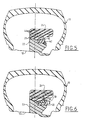
- the means for holding or blocking the second part radially outer 24 on the first piece radially internal 22 no longer include grooves and ribs complementary to their frustoconical surfaces, but a annular element 40 forming a corner, which is engaged to force between an external surface of the first part radially internal 22 and a frustoconical surface inside of the second radially outer part 24, the annular element 40 being maintained in an axial position on the first radially internal part 22 by a removable stop 42 such as an engaged split washer in a groove in the outer surface of the first radially internal part 22.
- the surface interior of the second radially outer part 24 is biconical in shape, its diameter increasing from the middle of this room inwards and towards outside of the tire, a first conical part of this interior surface cooperating with a surface conical complementary to the annular element 40, the other conical part of this inner surface cooperating with a conical surface complementary to the first part radially internal 22.
- the second radially external annular part 24 comprises, in addition as soon as covered with inextensible cords 28, strips 44 of inextensible material which are radially outside of the cable plies 28, so to avoid any risk of deformation of the part radially external 24 in use.
- the annular element 40 can form a ring continuous or be open at at least one point in its periphery. In the first case, it must be mounted on a frustoconical surface of the first piece radially internal 22 to tighten it on the rim when it is pushed between the two pieces. In the second case, it can be mounted on a cylindrical surface of the first radially internal part, as shown in FIG. 5.
- the fitting of the second radially external part 24 on the first and its locking in position are ensured by an open annular element 46 forming a corner, carried by an annular ring 48 split radially and having a threaded internal cylindrical surface for able to be screwed onto an external cylindrical surface corresponding thread of the first annular part radially internal 22.
- Pawns 50 are provided on the crown 48 to facilitate its rotation training around its axis and its screwing on the first part radially internal 22.
- Interlocking and maintaining or blocking the second radially external part 24 on the first radially internal part 22 are therefore provided by screwing the crown 48 onto the first annular part radially internal 22.
- the socket and the holding the second annular piece radially external 24 on the first annular piece radially internal 22 are provided by means of an annular element 40 similar to that shown in FIG. 5, but which has holes 52 parallel to its axis for the receiving bolts 54 screwed into nuts 56 mounted in corresponding holes in the first room radially internal 22 or embedded in the material constituting it.
- the inner surface of the second radially outer part 24 is biconical as already described and cooperates with an external surface conical of the annular element 40 and a surface conical exterior of opposite inclination formed on the first radially internal annular part 22. In these conditions, screwing the bolts 54 into the nuts 56 ensures the force fit and maintenance of the second radially external annular part 24 on the first radially internal annular part 22.
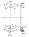
- the first radially annular piece internal 22 can be made in two semi-circular parts 22a and 22b as shown schematically in Figure 8, which facilitates their mounting on the rim 12, these two semi-circular parts 22a, 22b being able be easily maintained applied to the rim 12, until the bolts 54 are screwed in, using an O-ring 58 rubber mounted in a surface groove outer peripheral of these semicircular parts 22a, 22b.
- the annular element 40 or 48 can be locked by snap-fastening on the peripheral surface outside of the first radially internal part 22.
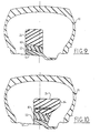
- Figures 9 and 10 show two alternative embodiments of the device according to the invention, in which a shaped intermediate piece 60 open ring, in relatively rigid material, by example the same as that of the first annular part radially internal 22, is interposed between this first radially internal part 22 and the second radially external annular part 24, which allows by example of halving the radial height of the first radially internal annular part 22 and therefore to facilitate its installation on the rim 12.
- the outer surface of the first part 22, the surfaces inside and outside of the intermediate piece 60 and the inner surface of the second annular part radially external 24 are frustoconical and are formed with grooves and ribs of the aforementioned type ensuring the holding in place, after fitting, of the part intermediate ring 60 on the first part radially internal annular 22 and of the second part radially external annular 24 on the annular part intermediate 60.
- the second radially annular piece external 24 ensures the clamping of the intermediate piece 60 on the first radially internal part 22, as well as tightening the first radially internal part 22 on rim 12.
- FIG. 10 differs from that of figure 9 by the number and the form circumferential holding grooves and ribs of the three annular parts one on the other and in this that the second radially outer annular part 24 comprises, as already described, a lateral flange 34 oriented towards the outer side of the tire 10.
- the first radially internal annular part 22, thus that the intermediate annular part 60 can be made in two or more arcuate curved parts of circle, to facilitate their mounting around the rim, these parts being easily held in place one after the other by means of an O-ring or analog housed in a groove in their peripheral surface exterior, as already described for the embodiment Figures 7 and 8.
- the first radially annular piece internal 22 and intermediate piece 60 can also be made in several parts connected end to end by elements clipped to be held on the rim until the second piece is mounted radially external 24. They can also be formed of a ring continuous open at a point on its periphery but comprising several deformable zones (2, 3 or more) allowing their arrangement around the rim. This allows in particular to produce parts ribbed, lighter, of plastic material having a high modulus of elasticity. In this case, the second radially outer annular piece 24 of rubber can have a large internal diameter and a thickness relatively weak radial.
- a layer of rubber or the like between the rim and the internal surface of the first part, in order to catch up or compensate for manufacturing tolerances, compensate any irregularities in the rim surface (e.g. veil weld points) and increase the coefficient of friction between the rim and the run-flat device.
- Figures 11 to 15 schematically represent a preferred mode of production of a run-flat device according to the invention, intended to be mounted on a wheel standard type motor vehicle, including rim 12 is non-removable one-piece and has edges side 16 for supporting and holding the heels 18 of a pneumatic 10 of the tubeless type.
- the rim 12 of the wheel is formed with an annular recess or rim groove 14 and with two circumferential ribs 120 of retaining the beads 18 of the tire, the rib 120 located on the outside of the wheel (the right side on Figures 11 to 15) protruding further inside the tire than the other rib 120 located on the inner side of the wheel, the outer side of the tire being subjected to greater forces in bend as the inner side of the tire.
- the improved variant of the run flat according to the invention comprises a part radially internal 22 made of relatively rigid material, such as plastic, an annular piece intermediate 124 in relatively rigid material such as than a plastic, and an annular piece radially external 24 substantially inextensible, the first two annular parts 22, 124 being open at least one point on their periphery, while the radially external annular part 24 is continuous.
- the radially internal annular part 22 is placed on rim 12, partly inside of the rim groove 14 and has a shape combined with that of the rim 12 to be immobilized in translation in a direction parallel to the wheel axis and to stop in the outside-inside direction of the wheel.
- the room intermediate ring 124 is mounted on the workpiece radially internal annular 22, the annular surfaces opposite parts 22 and 124 having shapes frustoconical conjugates and comprising one at least one annular groove 30 and the other at least one rib annular 32 having corresponding shapes, allowing to mount the intermediate annular part 124 on the radially internal part by interlocking and snap-fit, the rib 32 of the intermediate piece 124 being housed in the groove 30 of the piece radially internal 22 and ensuring axial positioning and holding the intermediate piece 124 in the axial position on the radially internal part 22.
- the outer peripheral surface of the room intermediate 124 is formed with a groove or groove 132 in U in which the annular part is housed radially external 24, this groove or groove 132 having a side face of the inner side of the wheel which is higher than its side on the outside of the wheel, which facilitates the assembly and disassembly of the radially outer annular part on the part intermediate annular 124 as will be seen below, and which also improves the axial support of the radially external part 24 on the part intermediate 124 in the event of efforts applied to the run-flat device from outside to inside the tire.
- the bottom of the throat 132 is substantially parallel to the axis of the part 124.
- the radially outer annular part 24 is of substantially rectangular section and comprises at least a layer of cords 28 which are substantially inextensible, made for example of polyester, fiberglass, "KEVLAR TM" fibers, of metal, etc ... which form neighboring or substantially contiguous turns inside a mass of rubber or any suitable material having a relatively low modulus of elasticity, a annular part 24 such as that shown in figure 11 which can be carried out by implementing methods conventional transmission belt manufacturing power, with fairly good dimensional accuracy.
- the device run flat is offset from the median plane equatorial 136 of the wheel and is more on the side from the outer side of the tire 10, the annular part intermediate 124 also having a lateral rim 34 oriented towards the outer side of the tire and forming stop for this sidewall when running flat or with a partially deflated tire, to avoid the tire.
- the annular parts 22, 124 are advantageously made of a plastic material polyamide type such as "NYRIM". Exhibits 22, 124 can be massive or ribbed to reduce their weight.
- the radial thickness of the part 24 is for example of the order of 20 mm.
- the wheel is placed at flat with its outer side on top, the piece radially internal annular 22 being in place around the rim, the intermediate annular part 124 being partially engaged on the radially internal part and the radially outer annular part 24 being in place on the intermediate piece 124.
- the outer heel 18 of the pneumatic is pushed into the inside of the throat rim 14 and, at a point on the periphery of the wheel, we introduces a tire lever 144 inside the rim groove, so that the end of this lever is inside the rim groove and that a intermediate part of the lever is supported on the side outside of the tire, at the side rim 34 of the intermediate piece 124.
- the angle at the top of the frustoconical surfaces conjugates of the radially internal part 22 and the intermediate piece 124 is relatively small, for example from 30 to 50 ° approximately, so that the effort for fitting the intermediate piece 124 onto the piece radially internal 22 is not very important.
- the effort that must be applied to the intermediate piece 124 to disengage from the radially internal part 22 is not very important, thanks to the rounded shapes cooperating external lateral faces of the groove 30 and rib 32 above, but is clearly sufficient for the individual parts to remain held in place during use.
- the internal diameter of the annular part radially external 24 is determined to maintain the parts 22 and 124 clamped one on the other and on the rim 12 respectively by resisting the forces of rolling, when this radially external part 24 is in place on the intermediate piece 124.
- the radially internal annular part 22 can be immobilized in rotation on the rim 12 by the valve 146 for inflating the tire (FIGS. 18 and 19) when this valve is metallic, the radially internal part 22 being placed on the rim so that the valve inflation 146 extends between its ends 148.
- the opening formed between the ends 150 of the intermediate annular part 124 is diametrically opposite the inflation valve 146.
- the annular part intermediate 124 includes a local rib 152 in protruding from its internal surface, this rib being diametrically opposite the ends 150 of the part intermediate 124 so as to be engaged between the ends 148 of the radially internal part 22 and at immobilize in rotation the intermediate piece 124 on the radially internal part 22.
- the ends 150 of the intermediate piece 124 are separated from each other in the free state of one. distance which is at least equal to or greater than the difference between the external peripheral dimension of the intermediate piece 124 and the peripheral dimension internal of the radially external part 24 so that that when these ends 150 are brought together one of the other, the external peripheral dimension of the part intermediate 124 becomes equal or slightly lower to the internal peripheral dimension of the part radially external 24.
- the distance between the ends 148 of the radially internal annular part 22 is determined to allow a good balance in rotation of the run-flat device when the openings of the annular parts 22 and 124 are diametrically opposed to each other as shown schematically in Figures 18 and 19.
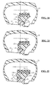
- the run-flat device differs from that of the preceding figures by the configuration of the frustoconical conjugate surfaces of the part radially internal 22 and intermediate piece 124.
- the frustoconical peripheral surface of the radially internal part 22 is formed with a groove 30 with rounded section on the side of its outer flank and with a radial rim 154 on its inner flank, the internal peripheral surface of the intermediate piece 124 being of complementary shape and therefore comprising a rib 32 with curved section in the vicinity of its side outside, and a recess 156 on its side inside.
- This configuration reduces the effort for fitting the intermediate piece 124 onto the piece radially internal 22.
- the frustoconical surfaces of parts 22 and 124 are each formed with a groove and a rib, the groove formed in the outer peripheral surface of the radially internal part 22 receiving the rib formed on the inner peripheral surface of the part intermediate 124, while the rib formed on the outer peripheral surface of the part radially internal 22 engages in the groove formed in the inner peripheral surface of the intermediate piece 124.
- the groove 30 formed in the surface radially internal external peripheral of the part 22 and the rib 32 formed in the peripheral surface interior of intermediate piece 124 are more closer to the inner sides of these parts than in the embodiment of FIGS. 11 to 15, and the side interior of the intermediate piece 124 is formed with a annular boss 158 forming a bearing surface on which one will come to exert a push as represented schematically by the arrows 142 in FIG. 15, for the disassembly of the run-flat device according to the invention.
- the groove 132 formed in the surface outer peripheral of the intermediate piece 124 a side walls which diverge from each other towards the outside, the inner peripheral surface of the radially outer part 24 being shaped which makes it easier to catch up manufacturing tolerances when mounting the part radially outer 24 on the workpiece intermediate 124.
- the outer peripheral surface of the part radially internal 22 is formed, in the vicinity of its. inner flank, with a rounded section rib which engages in a groove of complementary shape to the inner peripheral surface of the intermediate piece 124, and includes on its outer flank a recess annular in which engages a peripheral rim radial of the inner flank of the intermediate piece 124.
- annular piece radially outer 24 is formed by two layers of material having different hardnesses, an outer layer 160 of greater hardness containing inextensible cords 38 and an inner layer 162 of lower hardness, which is engaged in the groove of the peripheral surface outside of the intermediate piece 124 and the lower hardness better compensates for manufacturing tolerances.
- the run-flat device differs from precedent basically in that the annular piece radially external 24 is no longer section rectangular, but has a peripheral surface internal of frustoconical shape which is housed in a groove in the outer peripheral surface of the part intermediate 124, the bottom of this groove forming also a frustoconical surface relative to the axis of the intermediate piece 124, the frustoconical surfaces mentioned above widening from the outside towards inside the wheel.
- This configuration facilitates the mounting of the radially external part 24 on the intermediate part 124, but increases the volume and mass of the room radially outer annular 24.
- locking and unlocking of the intermediate annular part on the first can be done with any tool or any machine for applying localized pressure or circumferential on the sidewall of the tire.
Landscapes
- Engineering & Computer Science (AREA)
- Mechanical Engineering (AREA)
- Tires In General (AREA)
- Support Of The Bearing (AREA)
Claims (35)
- Notlaufvorrichtung für ein Kraftfahrzeug zum Aufspannen auf eine reguläre Felge (12) mit seitlichen Rändern (16) zum Halten der Wülste (18) eines Luftreifens, dadurch gekennzeichnet, daß sie aus mindestens zwei aufeinandergesteckten koaxialen Ringteilen (22, 24) besteht, wobei das in Radialrichtung innere Teil aus einem relativ steifen Werkstoff besteht und um die Felge einen offenen Ring bildet, und das in Radialrichtung äußere Teil auf der Basis eines elastisch verformbaren Werkstoffes ist und einen einstückigen, kontinuierlichen Ring aufweist, der das in Radialrichtung innere Ringteil (22) umgibt und einen Innendurchmesser aufweist, der im wesentlichen gleich oder größer als der Außendurchmesser eines seitlichen Randes (16) der Felge ist.
- Vorrichtung nach Anspruch 1, dadurch gekennzeichnet, daß das in Radialrichtung äußere Teil (24) einen Innendurchmesser aufweist, der geringfügig kleiner als der Außendurchmesser des in Radialrichtung inneren Ringteils (22) ist, und durch Krafteinwirkung auf dieses aufgesteckt ist.
- Vorrichtung nach Anspruch 1 oder 2, dadurch gekennzeichnet, daß das in Radialrichtung äußere Ringteil (24) ringförmige Mittel (28, 44) aufweist, die im wesentlichen nicht dehnbar und beispielsweise in das Material eingebettet sind, aus dem das in Radialrichtung äußere Teil besteht.
- Vorrichtung nach einem der vorhergehenden Ansprüche, dadurch gekennzeichnet, daß die Kontaktflächen zwischen den beiden koaxialen Teilen (22, 24) zumindest teilweise stumpfkegelförmig sind.
- Vorrichtung nach einem der vorhergehenden Ansprüche, dadurch gekennzeichnet, daß sie Mittel zum axialen Halten des in Radialrichtung äußeren Teils (24) auf dem in Radialrichtung inneren Teil aufweist.
- Vorrichtung nach Anspruch 5, dadurch gekennzeichnet, daß die Mittel zum axialen Halten ein ringförmiges Element (40, 46, 48) aufweisen, das einen Keil zwischen dem in Radialrichtung inneren und äußeren Teil bildet und durch Befestigungs- bzw. Blockiermittel zwischen diesen beiden Teilen in Position gehalten wird.
- Vorrichtung nach Anspruch 6, dadurch gekennzeichnet, daß die Befestigungsmittel Schrauben (54) aufweisen, die parallel zur Achse der Felge und in entsprechende Löcher des ringförmigen Elementes (40) und des in Radialrichtung inneren Teils (22) eingesetzt sind.
- Vorrichtung nach Anspruch 7, dadurch gekennzeichnet, daß die Schrauben in Muttern (56) eingeschraubt sind, die in den genannten Löchern des in Radialrichtung inneren Teils vorgesehen oder in dem dieses Teil bildenden Material eingebettet sind.
- Vorrichtung nach Anspruch 6, dadurch gekennzeichnet, daß das ringförmige Element (48) eine zylindrische Innenfläche mit Gewinde aufweist und auf eine entsprechende, mit einem Gewinde versehene zylindrische Lagerfläche des in Radialrichtung inneren Teils (22) aufgeschraubt ist.
- Vorrichtung nach Anspruch 6, dadurch gekennzeichnet, daß das ringförmige Element (40) auf dem in Radialrichtung inneren Teil durch Einrasten oder mittels einer Schlitzscheibe (42) in Position gehalten wird, welche in einer Kehlung einer Umfangsfläche des in Radialrichtung inneren Teils (22) sitzt.
- Vorrichtung nach Anspruch 5, dadurch gekennzeichnet, daß die Mittel zum axialen Halten des in Radialrichtung äußeren Teils (24) auf dem in Radialrichtung inneren Teil Umfangsnuten und -rippen (30, 32) aufweisen, die in Kontaktflächen zwischen dem in Radialrichtung inneren und äußeren Ringteil ausgebildet sind.
- Vorrichtung nach einem der vorhergehenden Ansprüche, dadurch gekennzeichnet, daß sie ein koaxiales offenes ringförmiges Zwischenteil (60, 124) aufweist, das zwischen dem in Radialrichtung inneren (22) und äußeren (24) Teil eingefügt ist.
- Vorrichtung nach Anspruch 12, dadurch gekennzeichnet, daß die Kontaktflächen des in Radialrichtung inneren Teils (22) und des ringförmigen Zwischenteils zumindest teilweise stumpfkegelförmig sind.
- Vorrichtung nach Anspruch 12 oder 13, dadurch gekennzeichnet, daß sie Mittel zum axialen Aufeinanderhalten des in Radialrichtung inneren Teils und des Zwischenteils (22, 60) aufweist, wobei diese Mittel beispielsweise derart sind, daß in den Kontaktflächen zwischen diesen beiden Teilen Nuten und Rippen ausgebildet sind.
- Vorrichtung nach einem der vorhergehenden Ansprüche, dadurch gekennzeichnet, daß das in Radialrichtung innere Ringteil und/oder das Zwischenteil (22, 60) aus steifem Plastikmaterial bestehen, und das in Radialrichtung äußere Ringteil (24) auf der Basis von Gummi oder Elastomer ist.
- Vorrichtung nach einem der vorhergehenden Ansprüche, dadurch gekennzeichnet, daß das in Radialrichtung innere Ringteil (22) aus mindestens zwei Abschnitten (22a, 22b) gebildet ist, die kreisbogenförmig gekrümmt und Ende an Ende um die Felge (12) angeordnet sind.
- Vorrichtung nach Anspruch 16, dadurch gekennzeichnet, daß die genannten Abschnitte (22a, 22b) des in Radialrichtung inneren Ringteils durch einen O-Ring (58) oder dergleichen, der in einer Kehlung der Außenfläche der Abschnitte (22a, 22b) sitzt, auf der Felge gehalten werden.
- Vorrichtung nach einem der vorhergehenden Ansprüche, dadurch gekennzeichnet, daß eine Schicht aus Gummi oder dergleichen zwischen der Felge (12) und dem in Radialrichtung inneren Ringteil (22) angeordnet ist.
- Notlaufvorrichtung für ein Kraftfahrzeug nach einem der Ansprüche 12 bis 18, welche mindestens ein in Radialrichtung inneres, offenes Ringteil (22) und ein in Radialrichtung äußeres, offenes ringförmiges Zwischenteil (124) aus einem relativ steifen Werkstoff aufweist, die dazu bestimmt sind, aufeinander um die Felge des Rades montiert zu werden, sowie ein kontinuierliches, in Radialrichtung äußeres Ringteil (24), das im wesentlichen nicht dehnbar ist und dazu bestimmt ist, auf dem in Radialrichtung äußeren, offenen ringförmigen Zwischenteil (124) montiert zu werden, dadurch gekennzeichnet, daß die äußere Umfangsfläche des ringförmigen Zwischenteils (124) mit einer Umfangskehlung bzw. -nut (132) zum Aufnehmen des in Radialrichtung äußeren Ringteils (24) ausgebildet ist, wobei diese Kehlung oder Nut (132) einen im wesentlichen U-förmigen Querschnitt besitzt.
- Vorrichtung nach einem der Ansprüche 12 bis 19, welche mindestens ein offenes ringförmiges Zwischenteil (124) aufweist, dadurch gekennzeichnet, daß die in Radialrichtung äußere Umfangsfläche des ringförmigen Zwischenteils (124) im wesentlichen parallel zur Achse dieses Teils ist.
- Vorrichtung nach einem der Ansprüche 1 bis 20, dadurch gekennzeichnet, daß das in Radialrichtung äußere Ringteil (24) einen im wesentlichen rechteckigen Querschnitt aufweist.
- Vorrichtung nach einem der Ansprüche 1 bis 21, dadurch gekennzeichnet, daß das in Radialrichtung äußere Ringteil (24) nicht-dehnbare Elemente wie etwa Lagen aus Kordfäden (28) aufweist, die in ein Material vom Typ Gummi eingebettet sind.
- Vorrichtung nach Anspruch 22, dadurch gekennzeichnet, daß das in Radialrichtung äußere Ringteil (24) zwei Schichten (160, 162) aus Gummi mit einer unterschiedlichen Härte aufweist.
- Vorrichtung nach einem der Ansprüche 1 bis 23, dadurch gekennzeichnet, daß das in Radialrichtung äußere Ringteil (24) reversibel ist.
- Vorrichtung nach einem der Ansprüche 12 bis 24, welche mindestens ein offenes ringformigeß Zwischenteil (124) aufweist, dadurch gekennzeichnet, daß die in Berührung stehenden Flächen des in Radialrichtung inneren Ringteils (22) und des ringförmigen Zwischenteils (124) im wesentlichen stumpfkegelförmig sind, mit einem Winkel am Scheitel in der Größenordnung von 30 bis 50°.
- Vorrichtung nach Anspruch 25, dadurch gekennzeichnet, daß die in Berührung stehenden Flächen des in Radialrichtung inneren Ringteils (22) und des ringförmigen Zwischenteils (124) wechselseitig jeweils mit mindestens einer Umfangsnut (30) und das andere mit mindestens einer Umfangsrippe (32) mit komplementärer Formgebung ausgebildet sind, die dazu bestimmt sind, sich ineinanderzufügen, wobei die Nut (30) und die Rippe (32) im Querschnitt eine nicht-symmetrische Formgebung mit einer schrägen oder gerundeten Außenseite aufweisen, die es gestattet, die Anstrengungen beim Montieren oder Demontieren dieser beiden Teile aufeinander zu verringern.
- Vorrichtung nach einem der Ansprüche 12 bis 26, welche mindestens ein offenes ringförmiges Zwischenteil (124) aufweist, dadurch gekennzeichnet, daß der Abstand zwischen Enden (150) des ringförmigen Zwischenteils (124) im freien zustand mindestens gleich der Differenz zwischen der Außenumfangsabmessung des ringförmigen Zwischenteils (124) im freien Zustand und der Innenumfangsabmessung des in Radialrichtung äußeren Ringteils (24) ist.
- Vorrichtung nach einem der Ansprüche 12 bis 27, welche mindestens ein offenes ringförmiges Zwischenteil (124) aufweist, dadurch gekennzeichnet, daß das in Radialrichtung innere Ringteil (22) und das ringförmige Zwischenteil (124) mit einem solchen Winkel zueinander angeordnet sind, daß ihre Öffnungen diametral entgegengesetzt sind, und das auf der Felge (12) angebrachte Aufblasventil (146) sich in die Öffnung des in Radialrichtung inneren Ringteils (22) einfügt.
- Vorrichtung nach einem der Ansprüche 12 bis 28, welche mindestens ein offenes ringformiges Zwischenteil (124) aufweist, dadurch gekennzeichnet, daß die Innenumfangsfläche des Zwischenteils (124) eine örtliche Rippe oder einen örtlichen Vorsprung (152) aufweist, die bzw. der dazu bestimmt ist, in die Öffnung des in Radialrichtung inneren Ringteils (22) eingefügt zu werden, um das ringförmige Zwischenteil (124) auf dem in Radialrichtung inneren Ringteil (22) an einer Drehung zu hindern.
- Vorrichtung nach einem der Ansprüche 12 bis 29, welche mindestens ein offenes ringförmiges Zwischenteil (124) aufweist, dadurch gekennzeichnet, daß eine Flanke des ringförmigen Zwischenteils (124) eine vorstehende ringförmige Erhebung (158) aufweist, die eine Abstützfläche für die Demontage der Vorrichtung aufweist.
- Vorrichtung nach einem der Ansprüche 12 bis 30, welche mindestens ein offenes ringförmiges Zwischenteil (124) aufweist, dadurch gekennzeichnet, daß der Boden der in der in Radialrichtung äußeren Umfangsfläche des ringförmigen Zwischenteils (124) für die Aufnahme des in Radialrichtung äußeren Ringteils (24) ausgebildeten Kehlung (132) gewellt ist.
- Verfahren zum Montieren einer Notlaufvorrichtung auf einem Rad eines Kraftfahrzeugs, dadurch gekennzeichnet, daß die Vorrichtung mindestens ein in Radialrichtung inneres Ringteil (22) und ein ringförmiges Zwischenteil (124) aus relativ steifem Material aufweist, die an mindestens einem Punkt ihres Umfangs offen und dazu bestimmt sind, aufeinander um die Felge (12) des Rades montiert zu werden, sowie ein kontinuierliches und zu den beiden vorgenannten koaxiales, in Radialrichtung äußeres Ringteil (24), wobei dieses in Radialrichtung äußere Teil im wesentlichen nicht dehnbar ist und einen Innendurchmesser aufweist, der größer als der Außendurchmesser des Randes (16) der Felge ist, sowie dadurch, daß es darin besteht, das in Radialrichtung innere offene Ringteil (22) auf der Felge (12) zu montieren, wobei das in Radialrichtung innere Teil auf der Felge (12) in Querverschiebung blockiert ist, das ringförmige Zwischenteil (124) ins Innere des Luftreifens (10) einzuführen und es um die Felge (12) benachbart zu dem in Radialrichtung inneren Ringteil (22) anzuordnen, das in Radialrichtung äußere Ringteil (24) ins Innere des Reifens einzuführen und es auf dem ringförmigen Zwischenteil (124) zu montieren, daraufhin die aus dem ringförmigen Zwischenteil und dem in Radialrichtung äußeren Teil (124, 24) gebildete Einheit bis zum Einrasten auf das in Radialrichtung innere Ringteil zu schieben, wobei die dem in Radialrichtung inneren Ringteil und dem ringförmigen Zwischenteil (22, 124) gegenüberliegenden Ringflächen eine komplementäre, insbesondere stumpfkegelförmige Formgebung aufweisen, mit Mitteln wie Rippen (32) und Nuten (28) mit komplementärer Formgebung, wobei diese Ringflächen so zusammenwirken, daß sie gleichzeitig das Einspannen des in Radialrichtung inneren Teils (22) auf der Felge (12) und die axiale Positionierung und das Festlegen des ringförmigen Zwischenteils (124) auf dem in Radialrichtung inneren Teil (22) bewirken.
- Verfahren nach Anspruch 32, dadurch gekennzeichnet, daß es dadurch, daß das in Radialrichtung äußere Ringteil (24) im freien Zustand einen Innendurchmesser aufweist, der kleiner als der Außendurcbmesser des ringförmigen Zwischenteils (124) ist, darin besteht, das ringförmige Zwischenteil (124) durch gegenseitiges Annähern seiner Enden vor dem Montieren des in Radialrichtung äußeren ringförmigen Teils (24) auf dem Zwischenteil um die Felge (12) zu verengen.
- Verfahren zum Demontieren einer durch Ausführen des Verfahrens nach Anspruch 32 oder 33 auf einem Rad montierten Notlaufvorrichtung, dadurch gekennzeichnet, daß es darin besteht, das ringförmige Zwischenteil (124) in eine zur Schubrichtung beim Montieren entgegengesetzte Richtung zu schieben, um die von dem ringförmigen Zwischenteil und dem in Radialrichtung äußeren Teil (124, 24) gebildete Einheit von dem in Radialrichtung inneren Ringteil (22) zu lösen, daraufhin das ringförmige Zwischenteil (124) auf sich selbst zu verengen, das in Radialrichtung äußere ringförmige Teil (24) von dem Zwischenteil (124) zu lösen und es von der Felge (12) zu lösen, daraufhin das ringförmige zwischenteil und das in Radialrichtung innere ringförmige Teil (124, 22) nacheinander von der Felge abzunehmen.
- Verfahren nach einem der Ansprüche 32 bis 34, dadurch gekennzeichnet, daß für die Montage und die Demontage der Notlaufvorrichtung der äußere Wulst (18) des Reifens (10) vom Rand (16) der Felge gelöst wird, um das Einführen der drei Ringteile (22, 124, 24) ins Innere des Reifens und ihre Anordnung um die Felge (12) zu ermöglichen.
Applications Claiming Priority (5)
| Application Number | Priority Date | Filing Date | Title |
|---|---|---|---|
| FR9713618A FR2770459B1 (fr) | 1997-10-30 | 1997-10-30 | Dispositif de roulage a plat pour vehicule automobile |
| FR9713618 | 1997-10-30 | ||
| FR9804225A FR2776963B1 (fr) | 1998-04-06 | 1998-04-06 | Dispositif de roulage a plat pour vehicule automobile et son procede de montage |
| FR9804225 | 1998-04-06 | ||
| PCT/FR1998/002330 WO1999022953A1 (fr) | 1997-10-30 | 1998-10-30 | Dispositif de roulage a plat pour vehicule automobile et son procede de montage |
Publications (2)
| Publication Number | Publication Date |
|---|---|
| EP0956212A1 EP0956212A1 (de) | 1999-11-17 |
| EP0956212B1 true EP0956212B1 (de) | 2002-05-08 |
Family
ID=26233906
Family Applications (1)
| Application Number | Title | Priority Date | Filing Date |
|---|---|---|---|
| EP98952826A Expired - Lifetime EP0956212B1 (de) | 1997-10-30 | 1998-10-30 | Notlaufvorrichtung für auto und verfahren zu seiner montage |
Country Status (6)
| Country | Link |
|---|---|
| US (1) | US6286574B1 (de) |
| EP (1) | EP0956212B1 (de) |
| CA (1) | CA2276710A1 (de) |
| DE (1) | DE69805277T2 (de) |
| ES (1) | ES2177077T3 (de) |
| WO (1) | WO1999022953A1 (de) |
Families Citing this family (15)
| Publication number | Priority date | Publication date | Assignee | Title |
|---|---|---|---|---|
| DE10001269B4 (de) * | 2000-01-14 | 2006-08-31 | Daimlerchrysler Ag | Fahrzeugrad für einen schlauchlosen Luftreifen |
| DE10011647C2 (de) * | 2000-03-10 | 2003-02-20 | Continental Ag | Fahrzeugrad mit Felge und schlauchlosem Luftreifen und mit ringförmigen Notlaufstützkörper |
| DE10011673C2 (de) * | 2000-03-10 | 2003-02-20 | Continental Ag | Fahrzeugrad mit Felge und schlauchlosem Luftreifen und mit ringförmigen Notlaufstützkörper |
| US6360800B1 (en) * | 2000-06-05 | 2002-03-26 | Hutchinson Sa | Runflat wheel for tubeless tire |
| IT1319474B1 (it) * | 2000-06-23 | 2003-10-10 | Corghi Spa | Dispositivo per operare su pneumatici del tipo system pax e simili |
| CA2422085A1 (en) * | 2000-09-11 | 2002-03-21 | Dow Global Technologies Inc. | Run flat tire support |
| FR2814118B1 (fr) * | 2000-09-21 | 2003-01-24 | Michelin Soc Tech | Appui de soutien de bande de roulement |
| FR2841825B1 (fr) * | 2002-07-08 | 2004-08-27 | Michelin Soc Tech | Jante de roue constituee de deux structures assemblees |
| US7400469B2 (en) * | 2003-09-16 | 2008-07-15 | Spectra Logic Corporation | Magazine-based library |
| US20050051249A1 (en) * | 2003-09-05 | 2005-03-10 | Lee Gul Nam | Run-flat tire |
| JP4382562B2 (ja) * | 2004-04-12 | 2009-12-16 | 株式会社ブリヂストン | ランフラットタイヤのランフラット走行寿命末期を判定する方法及び装置 |
| EP1778006A2 (de) * | 2004-07-26 | 2007-05-02 | Candis EHF. | Geformtes leichtes hochgeschwindigkeits-scherbrett mit erhöhter hydrodynamischer leistung und verwendungs- und herstellungsverfahren |
| US20060162834A1 (en) * | 2005-01-25 | 2006-07-27 | Chen Yueh N | Vehicle wheel rim assembly |
| CN101982324A (zh) * | 2010-10-21 | 2011-03-02 | 黄强 | 带化险减损环的汽车车轮 |
| CA3071943A1 (en) * | 2017-08-03 | 2019-02-07 | Hutchinson Industries, Inc. | Run flat system including a continuous elastomeric cap member |
Family Cites Families (18)
| Publication number | Priority date | Publication date | Assignee | Title |
|---|---|---|---|---|
| US1343685A (en) * | 1919-02-01 | 1920-06-15 | Arthur L Runyan | Resilient tire-filler |
| US2040645A (en) * | 1934-07-27 | 1936-05-12 | Fredrick S Dickinson | Noncollapsible tire |
| DE2319501A1 (de) * | 1973-04-17 | 1974-11-07 | Hans Wimmer | Fahrzeugluftreifen mit notlaufvorrichtung |
| US4374535A (en) * | 1975-09-30 | 1983-02-22 | The Goodyear Tire & Rubber Company | Wheel well filler |
| DE2658049A1 (de) * | 1976-12-22 | 1978-07-06 | Continental Gummi Werke Ag | Fahrzeugrad |
| JPS54122501A (en) * | 1978-03-14 | 1979-09-22 | Ohtsu Tire & Rubber Co Ltd | Safe wheel |
| US4183388A (en) * | 1978-07-24 | 1980-01-15 | General Motors Corporation | Run-flat tire having internal support means |
| FR2516868A1 (fr) * | 1981-11-20 | 1983-05-27 | Michelin & Cie | Support interne pour s'opposer a l'aplatissement d'un pneumatique |
| US4393911A (en) * | 1982-07-26 | 1983-07-19 | Astronics Corporation | Safety liner for tires |
| FR2555944B1 (fr) * | 1983-12-01 | 1986-07-18 | Michelin & Cie | Dispositif de blocage des bourrelets d'une enveloppe de pneumatique |
| US4722377A (en) * | 1984-06-11 | 1988-02-02 | The Goodyear Tire & Rubber Company | Tire safety support system |
| CA1237050A (en) * | 1984-09-10 | 1988-05-24 | Bernard J. O'coin | Flat proof tire with reuseable core and method of installation |
| US4854356A (en) * | 1985-07-26 | 1989-08-08 | Theodore Koutsoupidis | Safety apparatus for tire |
| US4662419A (en) * | 1986-02-06 | 1987-05-05 | Astronics Corporation | Beadlock for tubeless tires |
| US5435363A (en) * | 1993-02-19 | 1995-07-25 | Pender; David R. | Run-flat pneumatic tires including plural separate inserts |
| FR2719258B1 (fr) * | 1994-04-27 | 1996-07-19 | Hutchinson | Dispositif de roulage à plat pour véhicule automobile. |
| US5479976A (en) * | 1994-12-20 | 1996-01-02 | Cho; Woon-Je | Three-chamber tire |
| FR2729105A1 (fr) * | 1995-01-05 | 1996-07-12 | Hutchinson | Dispositif de roulage a plat pour vehicule automobile et son procede de fabrication |
-
1998
- 1998-10-30 US US09/331,192 patent/US6286574B1/en not_active Expired - Fee Related
- 1998-10-30 DE DE69805277T patent/DE69805277T2/de not_active Expired - Fee Related
- 1998-10-30 EP EP98952826A patent/EP0956212B1/de not_active Expired - Lifetime
- 1998-10-30 ES ES98952826T patent/ES2177077T3/es not_active Expired - Lifetime
- 1998-10-30 CA CA002276710A patent/CA2276710A1/fr not_active Abandoned
- 1998-10-30 WO PCT/FR1998/002330 patent/WO1999022953A1/fr active IP Right Grant
Also Published As
| Publication number | Publication date |
|---|---|
| WO1999022953A1 (fr) | 1999-05-14 |
| DE69805277T2 (de) | 2003-02-06 |
| DE69805277D1 (de) | 2002-06-13 |
| EP0956212A1 (de) | 1999-11-17 |
| ES2177077T3 (es) | 2002-12-01 |
| US6286574B1 (en) | 2001-09-11 |
| CA2276710A1 (fr) | 1999-05-14 |
Similar Documents
| Publication | Publication Date | Title |
|---|---|---|
| EP0956212B1 (de) | Notlaufvorrichtung für auto und verfahren zu seiner montage | |
| EP0796747B1 (de) | Notlaufring aus weichem Elastomermaterial für einen Reifen | |
| FR2472978A1 (fr) | Roue de vehicule | |
| EP2316663B1 (de) | Radfelge mit Speichen, damit ausgestattete montierte Einheit und Zusammenbauverfahren | |
| CA2781829A1 (fr) | Roue composite, notamment pour un cycle, et procede de fabrication d'une telle roue | |
| EP0679544B1 (de) | Notlaufvorrichtung für Auto | |
| EP0878328B1 (de) | Halbhohlreifen und Walze mit solchen Reifen | |
| EP1868823B1 (de) | Arretierungsring in einer anordnung zur montage eines reifens an einer fahrzeugnabe | |
| WO2008132348A1 (fr) | Dispositif de roulage a plat pour vehicule automobile et ensemble monte l'incorporant | |
| EP0430743A1 (de) | Ringförmige Notlaufeinrichtung | |
| EP1868824B1 (de) | System zur arretierung eines montagerings an einer fahrzeugnabe | |
| EP1420966B1 (de) | Schlauchlos montierte anordnung für ein fahrrad | |
| CH633223A5 (fr) | Ensemble de pneumatique et de jante de roue. | |
| FR2776963A1 (fr) | Dispositif de roulage a plat pour vehicule automobile et son procede de montage | |
| CA2475417A1 (fr) | Methode pour alleger un dispositif de roulage a plat de roue de vehicule automobile et dispositif ainsi obtenu | |
| EP0798141A1 (de) | Notlaufvorrichtung für Fahrzeug und Verfahren zu ihrer Montage | |
| FR2770459A1 (fr) | Dispositif de roulage a plat pour vehicule automobile | |
| EP1538007B1 (de) | Notlaufvorrichtung für Kraftfahrzeug und diese enthaltende Radeinheit | |
| WO2019122646A1 (fr) | Assemblage pour bandage | |
| FR2842140A1 (fr) | Ensemble monte tubeless pour cycle, jante et pneumatique tubeless | |
| EP1901928B1 (de) | Fahrzeugfelge mit sitzen mit nicht übereinstimmenden durchmessern | |
| FR2844480A1 (fr) | Roue de vehicule | |
| EP1190873A1 (de) | Notlauf-System für ein Kraftfahrzeug | |
| FR2843335A1 (fr) | Dispositif de securite pour les pneumatiques montes sur des jantes monobloc a gorge de montage. | |
| WO1994008803A1 (fr) | Cale de montage de pneumatiques |
Legal Events
| Date | Code | Title | Description |
|---|---|---|---|
| PUAI | Public reference made under article 153(3) epc to a published international application that has entered the european phase |
Free format text: ORIGINAL CODE: 0009012 |
|
| 17P | Request for examination filed |
Effective date: 19990629 |
|
| AK | Designated contracting states |
Kind code of ref document: A1 Designated state(s): DE ES FR GB IT NL SE |
|
| GRAG | Despatch of communication of intention to grant |
Free format text: ORIGINAL CODE: EPIDOS AGRA |
|
| 17Q | First examination report despatched |
Effective date: 20010827 |
|
| GRAG | Despatch of communication of intention to grant |
Free format text: ORIGINAL CODE: EPIDOS AGRA |
|
| GRAH | Despatch of communication of intention to grant a patent |
Free format text: ORIGINAL CODE: EPIDOS IGRA |
|
| REG | Reference to a national code |
Ref country code: GB Ref legal event code: IF02 |
|
| GRAH | Despatch of communication of intention to grant a patent |
Free format text: ORIGINAL CODE: EPIDOS IGRA |
|
| GRAA | (expected) grant |
Free format text: ORIGINAL CODE: 0009210 |
|
| AK | Designated contracting states |
Kind code of ref document: B1 Designated state(s): DE ES FR GB IT NL SE |
|
| REF | Corresponds to: |
Ref document number: 69805277 Country of ref document: DE Date of ref document: 20020613 |
|
| GBT | Gb: translation of ep patent filed (gb section 77(6)(a)/1977) |
Effective date: 20020812 |
|
| REG | Reference to a national code |
Ref country code: ES Ref legal event code: FG2A Ref document number: 2177077 Country of ref document: ES Kind code of ref document: T3 |
|
| PLBE | No opposition filed within time limit |
Free format text: ORIGINAL CODE: 0009261 |
|
| STAA | Information on the status of an ep patent application or granted ep patent |
Free format text: STATUS: NO OPPOSITION FILED WITHIN TIME LIMIT |
|
| 26N | No opposition filed |
Effective date: 20030211 |
|
| PGFP | Annual fee paid to national office [announced via postgrant information from national office to epo] |
Ref country code: FR Payment date: 20050830 Year of fee payment: 8 |
|
| PGFP | Annual fee paid to national office [announced via postgrant information from national office to epo] |
Ref country code: ES Payment date: 20050914 Year of fee payment: 8 |
|
| PGFP | Annual fee paid to national office [announced via postgrant information from national office to epo] |
Ref country code: GB Payment date: 20051004 Year of fee payment: 8 |
|
| PGFP | Annual fee paid to national office [announced via postgrant information from national office to epo] |
Ref country code: SE Payment date: 20051005 Year of fee payment: 8 |
|
| PGFP | Annual fee paid to national office [announced via postgrant information from national office to epo] |
Ref country code: NL Payment date: 20051028 Year of fee payment: 8 |
|
| PGFP | Annual fee paid to national office [announced via postgrant information from national office to epo] |
Ref country code: DE Payment date: 20051222 Year of fee payment: 8 |
|
| PG25 | Lapsed in a contracting state [announced via postgrant information from national office to epo] |
Ref country code: SE Free format text: LAPSE BECAUSE OF NON-PAYMENT OF DUE FEES Effective date: 20061031 |
|
| PGFP | Annual fee paid to national office [announced via postgrant information from national office to epo] |
Ref country code: IT Payment date: 20061031 Year of fee payment: 9 |
|
| PG25 | Lapsed in a contracting state [announced via postgrant information from national office to epo] |
Ref country code: NL Free format text: LAPSE BECAUSE OF NON-PAYMENT OF DUE FEES Effective date: 20070501 Ref country code: DE Free format text: LAPSE BECAUSE OF NON-PAYMENT OF DUE FEES Effective date: 20070501 |
|
| EUG | Se: european patent has lapsed | ||
| GBPC | Gb: european patent ceased through non-payment of renewal fee |
Effective date: 20061030 |
|
| NLV4 | Nl: lapsed or anulled due to non-payment of the annual fee |
Effective date: 20070501 |
|
| REG | Reference to a national code |
Ref country code: FR Ref legal event code: ST Effective date: 20070629 |
|
| PG25 | Lapsed in a contracting state [announced via postgrant information from national office to epo] |
Ref country code: GB Free format text: LAPSE BECAUSE OF NON-PAYMENT OF DUE FEES Effective date: 20061030 |
|
| REG | Reference to a national code |
Ref country code: ES Ref legal event code: FD2A Effective date: 20061031 |
|
| PG25 | Lapsed in a contracting state [announced via postgrant information from national office to epo] |
Ref country code: FR Free format text: LAPSE BECAUSE OF NON-PAYMENT OF DUE FEES Effective date: 20061031 Ref country code: ES Free format text: LAPSE BECAUSE OF NON-PAYMENT OF DUE FEES Effective date: 20061031 |
|
| PG25 | Lapsed in a contracting state [announced via postgrant information from national office to epo] |
Ref country code: IT Free format text: LAPSE BECAUSE OF NON-PAYMENT OF DUE FEES Effective date: 20071030 |