EP1538007B1 - Notlaufvorrichtung für Kraftfahrzeug und diese enthaltende Radeinheit - Google Patents
Notlaufvorrichtung für Kraftfahrzeug und diese enthaltende Radeinheit Download PDFInfo
- Publication number
- EP1538007B1 EP1538007B1 EP04291881A EP04291881A EP1538007B1 EP 1538007 B1 EP1538007 B1 EP 1538007B1 EP 04291881 A EP04291881 A EP 04291881A EP 04291881 A EP04291881 A EP 04291881A EP 1538007 B1 EP1538007 B1 EP 1538007B1
- Authority
- EP
- European Patent Office
- Prior art keywords
- ring
- rim
- lateral
- axially
- zone
- Prior art date
- Legal status (The legal status is an assumption and is not a legal conclusion. Google has not performed a legal analysis and makes no representation as to the accuracy of the status listed.)
- Expired - Lifetime
Links
- 239000011324 bead Substances 0.000 claims description 7
- 239000000463 material Substances 0.000 claims description 3
- 239000004033 plastic Substances 0.000 claims description 3
- 229920003023 plastic Polymers 0.000 claims description 3
- 239000005060 rubber Substances 0.000 claims description 3
- 229920001169 thermoplastic Polymers 0.000 claims description 2
- 238000005096 rolling process Methods 0.000 description 10
- 239000002184 metal Substances 0.000 description 3
- 229920002292 Nylon 6 Polymers 0.000 description 2
- 230000007423 decrease Effects 0.000 description 2
- 238000005192 partition Methods 0.000 description 2
- 239000004952 Polyamide Substances 0.000 description 1
- 238000005452 bending Methods 0.000 description 1
- 238000005119 centrifugation Methods 0.000 description 1
- 239000011248 coating agent Substances 0.000 description 1
- 238000000576 coating method Methods 0.000 description 1
- 230000000694 effects Effects 0.000 description 1
- 230000001050 lubricating effect Effects 0.000 description 1
- 229920002647 polyamide Polymers 0.000 description 1
- 229920000642 polymer Polymers 0.000 description 1
- 239000004416 thermosoftening plastic Substances 0.000 description 1
Images

Classifications
-
- B—PERFORMING OPERATIONS; TRANSPORTING
- B60—VEHICLES IN GENERAL
- B60B—VEHICLE WHEELS; CASTORS; AXLES FOR WHEELS OR CASTORS; INCREASING WHEEL ADHESION
- B60B21/00—Rims
-
- B—PERFORMING OPERATIONS; TRANSPORTING
- B60—VEHICLES IN GENERAL
- B60C—VEHICLE TYRES; TYRE INFLATION; TYRE CHANGING; CONNECTING VALVES TO INFLATABLE ELASTIC BODIES IN GENERAL; DEVICES OR ARRANGEMENTS RELATED TO TYRES
- B60C17/00—Tyres characterised by means enabling restricted operation in damaged or deflated condition; Accessories therefor
- B60C17/04—Tyres characterised by means enabling restricted operation in damaged or deflated condition; Accessories therefor utilising additional non-inflatable supports which become load-supporting in emergency
- B60C17/041—Tyres characterised by means enabling restricted operation in damaged or deflated condition; Accessories therefor utilising additional non-inflatable supports which become load-supporting in emergency characterised by coupling or locking means between rim and support
- B60C17/042—Tyres characterised by means enabling restricted operation in damaged or deflated condition; Accessories therefor utilising additional non-inflatable supports which become load-supporting in emergency characterised by coupling or locking means between rim and support preventing sliding or rotation between support and rim
-
- B—PERFORMING OPERATIONS; TRANSPORTING
- B60—VEHICLES IN GENERAL
- B60C—VEHICLE TYRES; TYRE INFLATION; TYRE CHANGING; CONNECTING VALVES TO INFLATABLE ELASTIC BODIES IN GENERAL; DEVICES OR ARRANGEMENTS RELATED TO TYRES
- B60C17/00—Tyres characterised by means enabling restricted operation in damaged or deflated condition; Accessories therefor
- B60C17/04—Tyres characterised by means enabling restricted operation in damaged or deflated condition; Accessories therefor utilising additional non-inflatable supports which become load-supporting in emergency
- B60C17/06—Tyres characterised by means enabling restricted operation in damaged or deflated condition; Accessories therefor utilising additional non-inflatable supports which become load-supporting in emergency resilient
- B60C17/061—Tyres characterised by means enabling restricted operation in damaged or deflated condition; Accessories therefor utilising additional non-inflatable supports which become load-supporting in emergency resilient comprising lateral openings
Definitions
- the present invention relates to a flat rolling device intended to equip a set mounted without a tube for a motor vehicle and such a mounted assembly incorporating this device, making it possible to travel a considerable distance at a relatively high speed when the assembled assembly is partially or totally deflated.
- the known flat rolling devices are generally constituted by a support ring which is mounted tightly around a wheel rim inside a tire casing.
- This ring is formed either in one piece with relatively flexible flanks that can be continuous or a slotted flexible piece (ie to which a slice has been removed), or at least two rigid pieces in an arc or sectors .
- This device comprises a support ring intended to be mounted on a single-piece type asymmetric wheel rim which has a rim ("drop center") and two rims axially inner and outer rim, said ring being made in minus two sectors independent of each other and each having radially inner and outer zones, and it is such that each sector is fixed to the rim at its radially inner zone by means of screws or a tightening belt which surrounds the outer lateral edges of the ring sectors.
- each ring sector terminates in an arcuate flange which is intended to bear on the bottom of the rim recess and which is formed by two internal and external lateral flanges, the internal flange. being housed in a lateral groove delimited by the rim recess while the outer rim, which matches the profile of the rim recess, cooperates with the means for fixing the sector of the ring on the rim.
- An object of the present invention is to provide a flat rolling device which is intended to be mounted in a hollow of an asymmetrical wheel rim of monobloc type, and which comprises a support ring having two lateral faces and divided into sectors.
- independent ring and a tightening belt adapted to be mounted in abutment on a radially internal bearing zone of one of said lateral faces so as to wedge each ring sector in the rim recess
- the belt comprising means rigid members adapted to exert a lateral and radial clamping force on the bearing zone of the ring sectors, when the latter and the belt are mounted coaxially and in juxtaposition against the two side walls of said hollow, so that the belt tightens the ring sectors against one of said side walls and against said rim recess, bearing on the other side wall, this device to optimize the wedging r adial while rolling in the inflated state of these ring sectors in the rim recess (i.e. by limiting the phenomenon of centrifugation of the ring by centri
- said belt advantageously comprises at least two rigid clamping zones which are respectively intended to press on said bearing zone and on said other lateral wall by circumferentially tensioning a flexible connection zone that comprises said belt and which connects said clamping areas to each other.
- axially inner and axially outer refer respectively to the sides of the wheel rim which are intended to be turned towards the inside and towards the outside of the motor vehicle, following assembly on a vehicle of a mounted assembly comprising this rim.
- said clamping zones move away from one another from said connecting zone which they extend laterally.
- said belt may advantageously comprise metal ribbons or plastics of axial section in the form of "U" each having wings respectively formed by said clamping zones and a core that comprises said connecting zone. These wings have a profile adapted to the side wall of the rim recess and to the side face of the ring.
- each of said wings may advantageously end with an end section which forms with said core an angle of between 50 ° and 80 °.
- said support zone may advantageously have a substantially frustoconical surface, which makes it possible to optimize the clamping of said ring sectors against said lateral wall.
- said belt may advantageously comprise rigid clamping sectors in a circular arc held spaced apart by means of an annular flexible band on which said clamping sectors are fixed, said flexible band having two ends remote from each other which are interconnected by a connection means of which they are provided.
- This connection means is adapted to adjust the tensioning of the belt.
- this belt is sufficiently flexible in torsion in its open position (i.e. before setting up said connection means), for mounting around the rim.
- said ring may comprise a radially inner face intended to be mounted on a bottom of said hollow and a radially outer face intended to support said flat-running envelope which is connected to said radially inner face by said lateral faces, the bearing zone of the ring being inclined radially outwards and axially towards the opposite lateral face of said ring.
- the opposite lateral face of said ring may comprise a radially internal abutment zone which is inclined radially outwards and axially toward said bearing zone, so that the axial section of said ring decreases radially. outwardly in said bearing and abutment zones.
- said lateral faces of said ring may advantageously extend radially outwards from said bearing and abutment zones, being parallel and then moving away from each other until to impart to said ring a maximum axial section equal to that of said radially outer face.
- each ring sector on the side of said abutment zone comprises a lateral flange in an arc which laterally extends said abutment zone and which is adapted to be mounted on a bearing said rim, said bottom of hollow being substantially flat in axial section.
- said lateral face of at least one of said ring sectors, on the side of said abutment zone is provided with a lateral projection adapted to cooperate locally in abutment with at least a notch formed in said rim, so as to prevent rotation in the circumferential direction of said ring sectors around said rim.
- said ring may advantageously be based on a rigid material, such as a polymer thermoplastic (for example a polyamide 6 or a polyamide 6.6), its radially outer face intended to support said casing in flat running may advantageously be based on rubber.
- a polymer thermoplastic for example a polyamide 6 or a polyamide 6.6
- This mounted assembly is characterized in that said belt comprises at least two rigid clamping zones which respectively support said bearing zone and said other lateral wall by circumferentially tensioning a flexible connection zone that comprises said belt and which connects said clamping areas to each other.
- said belt is mounted above a bottom of said hollow connecting said side walls to each other, being separated from said bottom by a circumferential radial clearance.
- said rim comprises in a known manner rim seats ("seat" in English) axially inner and outer respectively for receiving heels of the envelope, each seat being defined axially by one of said flanges and optionally by an adjacent circumferential boss, said axially outer side wall of said hollow extending axially and radially inwardly from said axially outer seat, said axially inner side wall of said hollow may advantageously extend axially and radially inwardly forming an undercut cooperating with a radially inner region of said axially internal lateral face of the ring, so as to block the ring on the rim.
- said device is such that said lateral face of each ring sector situated on the side of said abutment zone comprises a lateral flange in an arc of circle which extends said abutment zone and which is mounted on the rim axially within said recess, said recess bottom being substantially flat in axial section, and the rim is also such that said axially inner side wall of said recess extends axially and radially inwardly forming said counterpart -bare.
- the rim comprises axially inside said hollow one or more notches distributed locally on the circumference of the rim, said at least one notch co-operating locally in abutment with said one or more lateral projections of the rim. one or more said ring sectors, respectively, so as to immobilize the latter in rotation on said rim.
- the mounted assembly 1 shown in the figure 1 comprises a single-piece asymmetrical wheel rim 10 comprising a circumferential rim recess 11, a tire casing 20 mounted against axially inner and outer rims 12 and 13 of the rim 10, and a flat-running device 30 mounted in the rim Rim hollow 11 and intended to support the casing 20 following an inflation pressure drop inside the mounted assembly 1.
- the rim 10 has axially inner and outer rim seats 14 and 15 respectively for receiving bead 21, 22 of the casing 20, each rim seat 14, 15 being delimited axially by one of the flanges 12, 13 and by a circumferential boss 16, 17 adjacent.
- the rim recess 11 is advantageously located adjacent to the axially outer rim seat 15, and is defined by two axially inner and outer side walls 11a and 11b interconnected by a bottom 11c, the axially outer side wall 11b extending axially. and radially inward from the adjacent boss 17.
- this inner wall 11a extends radially inwardly forming an undercut which is inclined axially and radially inwards and which is intended to hold in place the sectors 31 'and 31 "under them. different stresses of rolling in the inflated and flat state.
- the bottom 11c of the rim recess 11 is slightly inclined axially outwards and radially inwards in the example of the figure 1 and it is adapted to receive the device 30 between the side walls 11a and 11b.
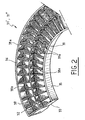
- This device 30 comprises a support ring 31 divided into at least two independent sectors 31 ', 31 "in the form of a circular arc (visible at figures 2 and 3 ), whose axially inner side face 32 is intended to be mounted against the axially inner wall 11a and whose face The axially outer side 33 is intended to be mounted against an annular clamping belt 34 which is itself intended to be mounted against the axially outer wall 11b.
- the ring 31 has a radially inner face 35 intended to be mounted on the bottom 11c of the recess 11 and a radially outer face 36 which is intended to support the casing 20 in flat rolling and which is connected to the radially inner face 35 by the two lateral faces 32 and 33.
- the ring 31 has a radially inner zone which is substantially intended to be comprised radially between the bottom 11c of the recess 11 and the respective apices of its side walls 11a and 11b.
- This radially internal zone is defined, on the one hand, by a bearing zone 33a of the outer lateral face 33 intended to be mounted in abutment against the belt 34 and, on the other hand, by an abutment zone 32a of the internal lateral face 32 intended to be mounted against the side wall 11a of the recess 11.
- each ring sector 31 ', 31 is each inclined radially outwards and axially toward each other, so that they each have a substantially frustoconical surface and that the axial section of said ring 31 decreases radially outwardly in the bearing areas 33a and abutment 32a.
- each ring sector 31 ', 31 "extend radially outwardly from the bearing zone 33a and abutment 32a, respectively, while being parallel and then moving away from one another. the other to be again parallel to the radially outer face 36, which has a maximum axial section.
- the ring sector 31 'or 31 "illustrated in FIG. figure 2 comprises a medial circumferential wall 38 in a crown arc which is provided at each of its sides with regularly spaced radial half-partitions 38a which extend laterally from the radially inner face 35 to the radially outer face 36 of the sector 31 ', 31 " so that their lateral edges define the lateral faces 32 and 33 of the ring sector 31 ', 31 ", and which are symmetrical to one another relative to the central wall 38.
- These half-partitions radial 38a are interconnected substantially at half radial height, on both sides of the central wall 38, by two circumferential half-walls 38b also symmetrical to each other with respect to this wall 38.
- Each ring sector 31 ', 31 " is based on a rigid material (such as a polyamide 6), and its radially outer face 36 is advantageously provided with a coating 37 made of rubber so as not to damage the liner. envelope when rolling flat.
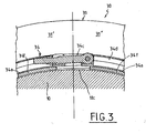
- the belt 34 illustrated in figure 1 is adapted to be sufficiently flexible in torsion for mounting on the rim 10 and advantageously comprises rigid sectors of arcuate clamping 34 ', 34 "(visible at the figure 3 ) held spaced apart by a flexible strip 34a open between its two ends 34b which are interconnected by a connecting means 34c.
- These clamping sectors 34 ', 34 "provided with the flexible band 34a which is itself provided with the connecting means 34c are intended to be mounted on the ring sectors 31', 31" (the assembly formed by the sectors 34 ', 34 ", the flexible band 34a and the connecting means 34c forming a single piece).
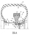
- each clamping sector 34 ', 34 “comprises rigid means adapted to exert a radial force F R and a lateral force F L of clamping (see FIG. figure 1 ) on the support zone 33a of the ring 31 and on the outer side wall 11b, when the ring 31 and the belt 34 are respectively mounted in juxtaposition against the side walls 11a and 11b of the recess 11, so that the belt 34 wedges each ring sector 31 ', 31 "on the bottom 11c of the recess 11 and against the inner side wall 11a.
- Each clamping sector 34 ', 34 is advantageously constituted by a flared" U “shaped axial section metal strip having two flanges 34d and 34e which respectively form two rigid clamping zones designed to press on the bearing zone. 33a and on the outer wall 11b of the recess 11, and a web 34f connecting the wings 34d and 34e to each other, each wing 34d, 34e ends with a substantially frustoconical end portion 34g which forms with the web 34f an angle ⁇ for example of the order of 65 °.
- the belt 34 is mounted on the rim 10 in such a way that it is above the bottom 11c of the recess 11 while being separated from this bottom 11c by a circumferential radial clearance, so that the wings 34d and 34e respectively can freely exert the radial and lateral clamping forces F R and F L on the ring 31 via the inner wing 34d, and on the outer wall 11b via the outer flange 34e.
- the belt 34 according to the invention is for example obtained by forming "U" metal or plastic strips forming the sectors 34 ', 34 "and then bending them in an arc, then connecting these sectors by fixing them on the flexible strip 34a (for example by means of a spot weld), the ends 34b of which are then connected together by the connection means 34c known per se of the toggle type (screw-nut), so as to give the belt
- the connection means 34c known per se of the toggle type (screw-nut)
- FIG. figure 3 shows in particular the opening between the two ends 34b of the belt 34 and the possible tightening of the ring sectors 31 'and 31 "by tensioning the belt 34 obtained by screwing the connecting means 34c.
- this lateral flange 132b which extends over the entire circumferential arc of each ring sector 131, advantageously makes it possible to increase the contact surface of the ring 131 on the rim 110 and the tilting behavior. lateral of the rolling device, as well as to "relieve" the belt 134 of the forces transmitted by taking up part of it.
- the mounting of the flatbed device 30 within the tire shell 20 is essentially as follows.
- a lubricating gel is then applied to the inner face 23 of the casing 20, before the outer bead 22 of the casing 20 is passed over the rim flange 13.
- the heels 21 and 22 are plate-mounted via the inflation pressure on their respective rim seats 14 and 15.
Landscapes
- Engineering & Computer Science (AREA)
- Mechanical Engineering (AREA)
- Tires In General (AREA)
- Arrangement Or Mounting Of Propulsion Units For Vehicles (AREA)
- Automatic Cycles, And Cycles In General (AREA)
- Automotive Seat Belt Assembly (AREA)
Claims (18)
- Vorrichtung zum Fahren mit plattem Reifen (30, 130), die dazu bestimmt ist, eine montierte Konstruktion (1, 101) ohne Luftkammer für ein Kraftfahrzeug auszustatten, umfassend eine asymmetrische Radfelge (10, 110) vom Monoblock-Typ, die eine Felgenvertiefung (11, 111), die durch zwei Seitenwände (11a und 11b, 111a und 111b) definiert wird, und einen Reifenmantel (20, 120), der auf die Felge (10, 110) montiert ist, umfasst, wobei die Vorrichtung (30, 130) dazu bestimmt ist, in die Felgenvertiefung (11, 111) montiert zu werden, um dem Mantel (20, 120) nach Abfall des Reifendrucks im Inneren der montierten Konstruktion (1, 101) Halt zu geben, wobei die Vorrichtung (30, 130) umfasst:- einen Stützring (31, 131) der in unabhängige Ringabschnitte (31', 31") aufgeteilt ist und zwei Seitenwände (32 und 33, 132 und 133) aufweist; und- einen ringförmigen Spanngürtel (34, 134), der angepasst ist, um als Stütze auf einer Stützzone (33a, 133a) radial innerhalb einer der Seitenwände (33, 133) des Rings (31, 131) montiert zu werden, derart, dass jeder Ringabschnitt (31', 31") in der Felgenvertiefung (11, 111) gestützt wird;wobei der Gürtel (34, 134) starre Mittel umfasst, die angepasst sind, um eine seitliche Spannkraft (FL) und eine radiale Spannkraft (FR) auf die Stützzone (33a, 133a) der Ringabschnitte (31', 31") auszuüben, wenn diese letzten und der Gürtel (34, 134) koaxial nebeneinander gegen die Seitenwände (11a und 11b, 111a und 111b) der Vertiefung (11, 111) derart montiert sind, dass der Gürtel (34, 134) die Ringabschnitte (31', 31") gegen eine der Seitenwände (11a, 111a) und gegen die Vertiefung (11, 111) gedrückt werden, indem die andere Seitenwand (11b, 111b) als Stütze genommen wird,
dadurch gekennzeichnet, dass der Gürtel (34, 134) wenigstens zwei starre Spannzonen (34d, 34e) umfasst, die jeweils dazu bestimmt sind, auf die Stützzone (33a, 133a) und auf die andere Seitenwand (11b, 111b) zu drücken, und zwar durch Unter-Umfangsspannung-Setzen einer weichen Bindungszone (34a, 34c, 34f), die den Gürtel (34, 134) aufweist und die die Spannzonen (34d, 34e) untereinander verbindet. - Vorrichtung (30, 130) nach Anspruch 1, dadurch gekennzeichnet, dass der Gürtel (34, 134) in wenigstens zwei Spannabschnitte (34', 34") aufgeteilt ist, die Mittels eines weichen ringförmigen Streifens (34a) verbunden sind, auf dem die Spannabschnitte (34', 34") fixiert sind und der zwei voneinander beabstandete Enden (34b) aufweist, die mit Hilfe eines Verbindungsmittels (34c) miteinander verbunden sind, das angepasst ist, um das Unter-Spannung-Setzen zu regulieren.
- Vorrichtung (30, 130) nach Anspruch 2, dadurch gekennzeichnet, dass der Gürtel (34, 134) Metall- oder Kunststoffbänder mit einem axialen Querschnitt in "U"-Form umfasst, die Flügel aufweisen, die jeweils die Spannzonen (34d, 34e) bilden, wobei die weiche Bindungszone (34a, 34c, 34f) den weichen Streifen (34a) umfasst, an dem ein Kern (34f) jedes Bandes befestigt ist, der den Flügeln (34d und 34e) gemeinsam ist, wobei der weiche Streifen (34a) an seinen Enden (34b) frei von dem Verbindungsmittel (34c) ist.
- Vorrichtung (30, 130) nach Anspruch 2 oder 3, dadurch gekennzeichnet, dass die Spannabschnitte (34', 34") durch Punkte auf dem weichen Streifen (34a) angeschweißt sind.
- Vorrichtung (30, 130) nach einem der vorangehenden Ansprüche, dadurch gekennzeichnet, dass die Stützzone (33a, 133a) eine etwa kegelstumpfförmige Oberfläche aufweist.
- Vorrichtung (30, 130) nach einem der Ansprüche 3 bis 5, dadurch gekennzeichnet, dass jeder der Flügel (34d und 34e) in einem Endteilstück (34g) endet, das mit dem Kern (34f) einen Winkel zwischen 50° und 80° bildet.
- Vorrichtung (30, 130) nach einem der vorangehenden Ansprüche, dadurch gekennzeichnet, dass der Ring (31, 131) eine radial innere Seite (35, 135), die dazu bestimmt ist, an einem Boden (11c, 111c) der Vertiefung (11, 111) montiert zu werden, und eine radial äußere Seite (36, 136) aufweist, die dazu bestimmt ist, den Mantel (20, 120) beim Fahren auf den Felgen zu stützen, die mit der radial inneren Seite (35, 135) durch die Seitenflächen (132 und 133) verbunden ist, wobei die Stützzone (33a, 133a) des Rings (31, 131) radial nach außen und axial gegen die gegenüberliegende Seitenfläche (32, 132) des Rings (31, 131) abgeschrägt ist.
- Vorrichtung (30, 130) nach Anspruch 7, dadurch gekennzeichnet, dass die gegenüberliegende Seitenfläche (32, 132) des Rings (31, 131) eine radial innere Anschlagszone (32a, 132a) umfasst, die radial gegen das Äußere und axial gegen die Stützzone (33a, 133a) abgeschrägt ist, derart, dass der axiale Abschnitt des Rings (31, 131) sich radial nach außen in der Stützzone (33a, 133a) und der Anschlagszone (32a, 132a) verjüngt.
- Vorrichtung (30) nach Anspruch 8, dadurch gekennzeichnet, dass sich die Seitenflächen (32 und 33) des Rings (31) radial nach außen ausgehend von der Stützzone (33a) und der Anschlagszone (32a) verlängern und parallel sind, sich dann voneinander entfernen, bis sie dem Ring (31) einen maximalen axialen Abschnitt verleihen, der gleich dem der radial äußeren Fläche (36) ist.
- Vorrichtung (130) nach Anspruch 8, dadurch gekennzeichnet, dass die Seitenfläche (132) jedes Ringabschnitts (131) die neben der Anschlagszone (132a) gelegen ist, einen lateralen Rand (132b) als Kreisbogen umfasst, der die Anschlagszone (32a) seitlich verlängert und der angepasst ist, um auf eine Auflagefläche der Felge (110) montiert zu werden, wobei der Boden der Vertiefung (111c) im axialen Schnitt ungefähr eben ist.
- Vorrichtung nach Anspruch 8, dadurch gekennzeichnet, dass die Seitenfläche (32) wenigstens eines der Ringabschnitte (31', 31") die neben der Anschlagszone (32a) gelegen ist, frei von einer seitlichen Auskragung (39) ist, welche angepasst ist, um lokal als Anschlag mit wenigstens einer Aussparung, die in der Felge gebildet ist, zu kooperieren, derart, dass die Drehung in der Umfangsrichtung der Ringabschnitte (31', 31") um die Felge verhindert wird.
- Vorrichtung (30, 130) nach einem der vorangehenden Ansprüche, dadurch gekennzeichnet, dass der Ring (31, 131) aus einem starren Material wie einem thermoplastischen Polymer ist, wobei seine radial äußere Fläche (36, 136), die dazu bestimmt ist, den Mantel (20, 120) beim Fahren mit plattem Reifen zu stützen, auf Kautschuk-Basis ist.
- Montierte Konstruktion (1, 101) ohne Luftkammer für ein Kraftfahrzeug, umfassend eine asymmetrische Radfelge (10, 110) vom Monoblock-Typ, die eine Felgenvertiefung (11, 111), die durch zwei Seitenwände, axial innen und außen, (11a und 11b, 111a und 111b), die miteinander durch einen Boden (11c, 111c) verbunden sind, definiert wird, einen Reifenmantel (20, 120), der gegen axial innere und äußere Randleisten (12 und 13, 112 und 113) der Felge (10, 110) montiert ist, und eine Vorrichtung zum Fahren mit plattem Reifen (30, 130), die in der Felgenvertiefung (11, 111) montiert ist und dazu bestimmt ist, den Mantel (20, 120) nach Abfall des Reifendrucks im Inneren der montierten Konstruktion (1, 101) zu stützen, wobei die Vorrichtung (30, 130) umfasst:- einen Stützring (31, 131), der in unabhängige Ringabschnitte (31', 31") aufgeteilt ist und zwei axial innere und äußere Seitenflächen (32 und 33, 132 und 133) aufweist, wobei der Ring (31, 131) an dem Boden der Vertiefung (11c, 111c) als Anschlag gegen die innere Seitenwand (11a, 111a) montiert ist, und- einen ringförmigen Spanngürtel (34, 134), der als Stütze in koaxialer Art an der Stützzone (33a, 133a) radial innerhalb der äußeren Seitenfläche (33, 133) des Rings (31, 131) derart montiert ist, dass jeder Ringabschnitt (31', 31") in der Vertiefung (11, 111) gestützt ist, und der gegen die äußere Seitenwand (11b, 111b) montiert ist,wobei der Gürtel (34, 134) starre Mittel umfasst, die angepasst sind, um eine seitliche Spannkraft (FL) und eine radiale Spannkraft (FR) auf die Stützzone (33a, 133a) der Ringabschnitte (31', 31") auszuüben, derart, dass der Gürtel (34, 134) die Ringabschnitte (31', 31") gegen die innere Seitenwand (11a, 111a) und gegen die Felgenvertiefung (11, 111) drückt, wobei die äußere Seitenwand (11b, 111b) als Stütze genommen wird,
dadurch gekennzeichnet, dass der Gürtel wenigsten zwei starre Spannzonen (34d, 34e) umfasst, die jeweils auf die Stützzone (33a, 133a) und die andere Seitenwand (11b, 111b) drücken, und zwar durch Unter-Umfangsspannung-Setzen einer weichen Bindungszone (34a, 34c, 34f), die den Gürtel (34, 134) trägt und die die Spannzonen (34d, 34e) untereinander verbindet. - Montierte Konstruktion (1, 101) nach Anspruch 13, dadurch gekennzeichnet, dass der Gürtel (34, 134) oberhalb eines Bodens (11c, 111c) der Vertiefung (11, 111), der die Seitenwände (11a und 11b, 111a und 111b) miteinander verbindet, montiert ist, wobei er von dem Boden (11c, 111c) durch ein radiales Umfangsspiel getrennt ist.
- Montierte Konstruktion (1, 101) nach Anspruch 13 oder 14, dadurch gekennzeichnet, dass die Vorrichtung zum Fahren mit plattem Reifen (30, 130) wie in einem der Ansprüche 2 bis 12 definiert ist.
- Montierte Konstruktion (1, 101) nach einem der Ansprüche 13 bis 15, wobei die Felge (10, 110) axial innere bzw. äußere Felgensitze (14 und 15, 114 und 115) umfasst, die dazu bestimmt sind, Wulste (21 und 22, 121 und 122) des Mantels (20, 120) aufzunehmen, wobei jeder Felgensitz (14 und 15, 114 und 115) axial in einer der Randleisten (12 und 13, 112 und 113) endet, wobei sich die axial äußere Seitenwand (11b, 111b) der Vertiefung (11, 111) axial und radial ausgehend von dem axial äußeren Sitz (15, 115) in das Innere erstreckt, dadurch gekennzeichnet, dass sich die axial innere Seitenwand (11a, 111a) der Vertiefung (11, 111) axial und radial in das Innere erstreckt, indem sie eine Hinterschneidung bildet, die mit einer radial inneren Zone der axial inneren Seitenfläche (32, 132) des Rings (31, 131) derart kooperiert, dass der Ring (31, 131) an der Felge (10, 110) blockiert wird.
- Montierte Konstruktion (101) nach Anspruch 16, dadurch gekennzeichnet, dass die Seitenfläche (132) jedes Ringabschnitts (131) die neben der Anschlagszone (132a) gelegen ist, einen lateralen Kragen (132b) als Kreisbogen umfasst, der die Anschlagszone (132a) verlängert und axial auf der Felge (110) im Inneren der Vertiefung (111) montiert ist, wobei der Boden (111c) der Vertiefung (111) im axialen Schnitt ungefähr eben ist.
- Montierte Konstruktion nach einem der Ansprüche 13 bis 15, wobei die Felge (10) die axial innere und äußere Felgensitze (14 und 15) umfasst, die dazu bestimmt sind, Wulste (21 und 22) des Mantels (20) aufzunehmen, wobei jeder Felgensitz (14 und 15) axial in einer der Randleisten (12 und 13) endet, die axial äußere Seitenwand (11b) der Vertiefung (11) ausgehend von dem axial äußeren Sitz (15) axial und radial in das Innere erstreckt, dadurch gekennzeichnet, dass die Vorrichtung (30) wie in Anspruch 12 definiert ist und dass die Felge (12) axial im Inneren der Vertiefung (11) ein oder mehrere Aussparungen lokal über den Umfang der Felge (10) verteilt umfasst, wobei die oder jede Aussparung lokal als Anschlag mit der lateralen Auskragung (39) wenigstens eines der Ringabschnitte (31', 31") derart kooperiert, dass diese letzte in der Rotation auf der Felge (10) immobilisiert wird.
Applications Claiming Priority (2)
| Application Number | Priority Date | Filing Date | Title |
|---|---|---|---|
| FR0314306A FR2863202B1 (fr) | 2003-12-05 | 2003-12-05 | Dispositif de roulage a plat pour vehicule automobile et ensemble monte |
| FR0314306 | 2003-12-05 |
Publications (2)
| Publication Number | Publication Date |
|---|---|
| EP1538007A1 EP1538007A1 (de) | 2005-06-08 |
| EP1538007B1 true EP1538007B1 (de) | 2008-10-29 |
Family
ID=34451729
Family Applications (1)
| Application Number | Title | Priority Date | Filing Date |
|---|---|---|---|
| EP04291881A Expired - Lifetime EP1538007B1 (de) | 2003-12-05 | 2004-07-23 | Notlaufvorrichtung für Kraftfahrzeug und diese enthaltende Radeinheit |
Country Status (5)
| Country | Link |
|---|---|
| EP (1) | EP1538007B1 (de) |
| AT (1) | ATE412538T1 (de) |
| CA (1) | CA2455001A1 (de) |
| DE (1) | DE602004017406D1 (de) |
| FR (1) | FR2863202B1 (de) |
Families Citing this family (1)
| Publication number | Priority date | Publication date | Assignee | Title |
|---|---|---|---|---|
| GB201812221D0 (en) * | 2018-07-26 | 2018-09-12 | Carbon Threesixty Ltd | A supporting member |
Family Cites Families (1)
| Publication number | Priority date | Publication date | Assignee | Title |
|---|---|---|---|---|
| FR2808734B1 (fr) * | 2000-05-11 | 2003-02-07 | Hutchinson | Dispositif de roulage a plat pour vehicule automobile |
-
2003
- 2003-12-05 FR FR0314306A patent/FR2863202B1/fr not_active Expired - Fee Related
-
2004
- 2004-01-08 CA CA002455001A patent/CA2455001A1/fr not_active Abandoned
- 2004-07-23 DE DE602004017406T patent/DE602004017406D1/de not_active Expired - Lifetime
- 2004-07-23 EP EP04291881A patent/EP1538007B1/de not_active Expired - Lifetime
- 2004-07-23 AT AT04291881T patent/ATE412538T1/de not_active IP Right Cessation
Also Published As
| Publication number | Publication date |
|---|---|
| ATE412538T1 (de) | 2008-11-15 |
| FR2863202B1 (fr) | 2006-05-05 |
| CA2455001A1 (fr) | 2005-06-05 |
| DE602004017406D1 (de) | 2008-12-11 |
| EP1538007A1 (de) | 2005-06-08 |
| FR2863202A1 (fr) | 2005-06-10 |
Similar Documents
| Publication | Publication Date | Title |
|---|---|---|
| EP1897705B1 (de) | Runflat-Vorrichtung für Kraftfahrzeug und damit ausgestattete montierte Einheit | |
| EP1097823B1 (de) | Felge zur Aufnahme eines Stützringes | |
| EP0748287A1 (de) | Luftreifen mit verbesserter struktur der wülste und einheit von einer reifenfelge | |
| EP2316663A1 (de) | Radfelge mit Speichen, damit ausgestattete montierte Einheit und Zusammenbauverfahren | |
| EP0956212B1 (de) | Notlaufvorrichtung für auto und verfahren zu seiner montage | |
| EP2139705B1 (de) | Notlaufvorrichtung für fahrzeuge und damit montierte anordnung | |
| EP2475535B1 (de) | Notlaufvorrichtung für ein auto, montierte baugruppe damit und zugehöriges montage-/demontageverfahren | |
| EP0600771B1 (de) | Verbesserte ringförmige Notlaufeinrichtung | |
| EP0430743A1 (de) | Ringförmige Notlaufeinrichtung | |
| CH636052A5 (en) | Wheel rim/tyre assembly | |
| EP0226967B1 (de) | Sicherheitsvorrichtung für ein Notlaufrad | |
| EP2206613A1 (de) | Notlaufvorrichtung für Kraftfahrzeug und Aufbau mit solcher Vorrichtung | |
| EP1153769B1 (de) | Notlaufvorrichtung für Fahrzeuge | |
| EP1538007B1 (de) | Notlaufvorrichtung für Kraftfahrzeug und diese enthaltende Radeinheit | |
| WO2006106051A2 (fr) | Anneau de verrouillage dans un ensemble de montage d'un pneumatique sur un moyeu de vehicule | |
| EP3727883A1 (de) | Anordnung für einen reifen | |
| FR2859662A1 (fr) | Methode pour alleger un dispositif de roulage a plat de roue de vehicule automobile et dispositif ainsi obtenu | |
| FR2776963A1 (fr) | Dispositif de roulage a plat pour vehicule automobile et son procede de montage | |
| EP1190873A1 (de) | Notlauf-System für ein Kraftfahrzeug | |
| FR2610249A1 (fr) | Dispositif de securite pour pneumatique sans chambre a air | |
| CA3252835A1 (fr) | Dispositif de roulement à plat | |
| EP1650056A1 (de) | Reifenwulstspreizring | |
| CH633221A5 (en) | Wheel rim and tyre assembly | |
| WO2020094977A1 (fr) | Bandage non pneumatique pour vehicule leger | |
| FR2903047A1 (fr) | Dispositif de roulage a plat pour vehicule automobile et ensemble monte l'incorporant. |
Legal Events
| Date | Code | Title | Description |
|---|---|---|---|
| PUAI | Public reference made under article 153(3) epc to a published international application that has entered the european phase |
Free format text: ORIGINAL CODE: 0009012 |
|
| AK | Designated contracting states |
Kind code of ref document: A1 Designated state(s): AT BE BG CH CY CZ DE DK EE ES FI FR GB GR HU IE IT LI LU MC NL PL PT RO SE SI SK TR |
|
| AX | Request for extension of the european patent |
Extension state: AL HR LT LV MK |
|
| 17P | Request for examination filed |
Effective date: 20050704 |
|
| AKX | Designation fees paid |
Designated state(s): AT BE BG CH CY CZ DE DK EE ES FI FR GB GR HU IE IT LI LU MC NL PL PT RO SE SI SK TR |
|
| 17Q | First examination report despatched |
Effective date: 20060109 |
|
| GRAP | Despatch of communication of intention to grant a patent |
Free format text: ORIGINAL CODE: EPIDOSNIGR1 |
|
| GRAS | Grant fee paid |
Free format text: ORIGINAL CODE: EPIDOSNIGR3 |
|
| GRAA | (expected) grant |
Free format text: ORIGINAL CODE: 0009210 |
|
| AK | Designated contracting states |
Kind code of ref document: B1 Designated state(s): AT BE BG CH CY CZ DE DK EE ES FI FR GB GR HU IE IT LI LU MC NL PL PT RO SE SI SK TR |
|
| REG | Reference to a national code |
Ref country code: GB Ref legal event code: FG4D Free format text: NOT ENGLISH |
|
| REG | Reference to a national code |
Ref country code: CH Ref legal event code: EP |
|
| REG | Reference to a national code |
Ref country code: IE Ref legal event code: FG4D Free format text: LANGUAGE OF EP DOCUMENT: FRENCH |
|
| REF | Corresponds to: |
Ref document number: 602004017406 Country of ref document: DE Date of ref document: 20081211 Kind code of ref document: P |
|
| NLV1 | Nl: lapsed or annulled due to failure to fulfill the requirements of art. 29p and 29m of the patents act | ||
| PG25 | Lapsed in a contracting state [announced via postgrant information from national office to epo] |
Ref country code: ES Free format text: LAPSE BECAUSE OF FAILURE TO SUBMIT A TRANSLATION OF THE DESCRIPTION OR TO PAY THE FEE WITHIN THE PRESCRIBED TIME-LIMIT Effective date: 20090209 Ref country code: AT Free format text: LAPSE BECAUSE OF FAILURE TO SUBMIT A TRANSLATION OF THE DESCRIPTION OR TO PAY THE FEE WITHIN THE PRESCRIBED TIME-LIMIT Effective date: 20081029 Ref country code: BG Free format text: LAPSE BECAUSE OF FAILURE TO SUBMIT A TRANSLATION OF THE DESCRIPTION OR TO PAY THE FEE WITHIN THE PRESCRIBED TIME-LIMIT Effective date: 20090129 |
|
| PG25 | Lapsed in a contracting state [announced via postgrant information from national office to epo] |
Ref country code: PL Free format text: LAPSE BECAUSE OF FAILURE TO SUBMIT A TRANSLATION OF THE DESCRIPTION OR TO PAY THE FEE WITHIN THE PRESCRIBED TIME-LIMIT Effective date: 20081029 Ref country code: NL Free format text: LAPSE BECAUSE OF FAILURE TO SUBMIT A TRANSLATION OF THE DESCRIPTION OR TO PAY THE FEE WITHIN THE PRESCRIBED TIME-LIMIT Effective date: 20081029 Ref country code: PT Free format text: LAPSE BECAUSE OF FAILURE TO SUBMIT A TRANSLATION OF THE DESCRIPTION OR TO PAY THE FEE WITHIN THE PRESCRIBED TIME-LIMIT Effective date: 20090330 Ref country code: SI Free format text: LAPSE BECAUSE OF FAILURE TO SUBMIT A TRANSLATION OF THE DESCRIPTION OR TO PAY THE FEE WITHIN THE PRESCRIBED TIME-LIMIT Effective date: 20081029 Ref country code: FI Free format text: LAPSE BECAUSE OF FAILURE TO SUBMIT A TRANSLATION OF THE DESCRIPTION OR TO PAY THE FEE WITHIN THE PRESCRIBED TIME-LIMIT Effective date: 20081029 |
|
| REG | Reference to a national code |
Ref country code: IE Ref legal event code: FD4D |
|
| PG25 | Lapsed in a contracting state [announced via postgrant information from national office to epo] |
Ref country code: IE Free format text: LAPSE BECAUSE OF FAILURE TO SUBMIT A TRANSLATION OF THE DESCRIPTION OR TO PAY THE FEE WITHIN THE PRESCRIBED TIME-LIMIT Effective date: 20081029 Ref country code: RO Free format text: LAPSE BECAUSE OF FAILURE TO SUBMIT A TRANSLATION OF THE DESCRIPTION OR TO PAY THE FEE WITHIN THE PRESCRIBED TIME-LIMIT Effective date: 20081029 Ref country code: DK Free format text: LAPSE BECAUSE OF FAILURE TO SUBMIT A TRANSLATION OF THE DESCRIPTION OR TO PAY THE FEE WITHIN THE PRESCRIBED TIME-LIMIT Effective date: 20081029 Ref country code: EE Free format text: LAPSE BECAUSE OF FAILURE TO SUBMIT A TRANSLATION OF THE DESCRIPTION OR TO PAY THE FEE WITHIN THE PRESCRIBED TIME-LIMIT Effective date: 20081029 |
|
| PG25 | Lapsed in a contracting state [announced via postgrant information from national office to epo] |
Ref country code: CZ Free format text: LAPSE BECAUSE OF FAILURE TO SUBMIT A TRANSLATION OF THE DESCRIPTION OR TO PAY THE FEE WITHIN THE PRESCRIBED TIME-LIMIT Effective date: 20081029 Ref country code: SE Free format text: LAPSE BECAUSE OF FAILURE TO SUBMIT A TRANSLATION OF THE DESCRIPTION OR TO PAY THE FEE WITHIN THE PRESCRIBED TIME-LIMIT Effective date: 20090129 |
|
| PLBE | No opposition filed within time limit |
Free format text: ORIGINAL CODE: 0009261 |
|
| STAA | Information on the status of an ep patent application or granted ep patent |
Free format text: STATUS: NO OPPOSITION FILED WITHIN TIME LIMIT |
|
| PG25 | Lapsed in a contracting state [announced via postgrant information from national office to epo] |
Ref country code: SK Free format text: LAPSE BECAUSE OF FAILURE TO SUBMIT A TRANSLATION OF THE DESCRIPTION OR TO PAY THE FEE WITHIN THE PRESCRIBED TIME-LIMIT Effective date: 20081029 |
|
| 26N | No opposition filed |
Effective date: 20090730 |
|
| BERE | Be: lapsed |
Owner name: HUTCHINSON Effective date: 20090731 |
|
| PG25 | Lapsed in a contracting state [announced via postgrant information from national office to epo] |
Ref country code: MC Free format text: LAPSE BECAUSE OF NON-PAYMENT OF DUE FEES Effective date: 20090731 |
|
| REG | Reference to a national code |
Ref country code: CH Ref legal event code: PL |
|
| PG25 | Lapsed in a contracting state [announced via postgrant information from national office to epo] |
Ref country code: LI Free format text: LAPSE BECAUSE OF NON-PAYMENT OF DUE FEES Effective date: 20090731 Ref country code: CH Free format text: LAPSE BECAUSE OF NON-PAYMENT OF DUE FEES Effective date: 20090731 |
|
| PG25 | Lapsed in a contracting state [announced via postgrant information from national office to epo] |
Ref country code: BE Free format text: LAPSE BECAUSE OF NON-PAYMENT OF DUE FEES Effective date: 20090731 |
|
| PG25 | Lapsed in a contracting state [announced via postgrant information from national office to epo] |
Ref country code: GR Free format text: LAPSE BECAUSE OF FAILURE TO SUBMIT A TRANSLATION OF THE DESCRIPTION OR TO PAY THE FEE WITHIN THE PRESCRIBED TIME-LIMIT Effective date: 20090130 |
|
| PG25 | Lapsed in a contracting state [announced via postgrant information from national office to epo] |
Ref country code: LU Free format text: LAPSE BECAUSE OF NON-PAYMENT OF DUE FEES Effective date: 20090723 |
|
| PG25 | Lapsed in a contracting state [announced via postgrant information from national office to epo] |
Ref country code: HU Free format text: LAPSE BECAUSE OF FAILURE TO SUBMIT A TRANSLATION OF THE DESCRIPTION OR TO PAY THE FEE WITHIN THE PRESCRIBED TIME-LIMIT Effective date: 20090430 |
|
| PG25 | Lapsed in a contracting state [announced via postgrant information from national office to epo] |
Ref country code: TR Free format text: LAPSE BECAUSE OF FAILURE TO SUBMIT A TRANSLATION OF THE DESCRIPTION OR TO PAY THE FEE WITHIN THE PRESCRIBED TIME-LIMIT Effective date: 20081029 |
|
| PG25 | Lapsed in a contracting state [announced via postgrant information from national office to epo] |
Ref country code: CY Free format text: LAPSE BECAUSE OF FAILURE TO SUBMIT A TRANSLATION OF THE DESCRIPTION OR TO PAY THE FEE WITHIN THE PRESCRIBED TIME-LIMIT Effective date: 20081029 |
|
| PGFP | Annual fee paid to national office [announced via postgrant information from national office to epo] |
Ref country code: DE Payment date: 20130722 Year of fee payment: 10 |
|
| PGFP | Annual fee paid to national office [announced via postgrant information from national office to epo] |
Ref country code: FR Payment date: 20130717 Year of fee payment: 10 Ref country code: GB Payment date: 20130719 Year of fee payment: 10 |
|
| PGFP | Annual fee paid to national office [announced via postgrant information from national office to epo] |
Ref country code: IT Payment date: 20130731 Year of fee payment: 10 |
|
| REG | Reference to a national code |
Ref country code: DE Ref legal event code: R119 Ref document number: 602004017406 Country of ref document: DE |
|
| GBPC | Gb: european patent ceased through non-payment of renewal fee |
Effective date: 20140723 |
|
| REG | Reference to a national code |
Ref country code: FR Ref legal event code: ST Effective date: 20150331 |
|
| PG25 | Lapsed in a contracting state [announced via postgrant information from national office to epo] |
Ref country code: DE Free format text: LAPSE BECAUSE OF NON-PAYMENT OF DUE FEES Effective date: 20150203 Ref country code: IT Free format text: LAPSE BECAUSE OF NON-PAYMENT OF DUE FEES Effective date: 20140723 |
|
| REG | Reference to a national code |
Ref country code: DE Ref legal event code: R119 Ref document number: 602004017406 Country of ref document: DE Effective date: 20150203 |
|
| PG25 | Lapsed in a contracting state [announced via postgrant information from national office to epo] |
Ref country code: FR Free format text: LAPSE BECAUSE OF NON-PAYMENT OF DUE FEES Effective date: 20140731 Ref country code: GB Free format text: LAPSE BECAUSE OF NON-PAYMENT OF DUE FEES Effective date: 20140723 |