EP0954840B1 - Vorrichtung zur anzeige von alpha-numerischen zeichen und/oder bildzeichen - Google Patents
Vorrichtung zur anzeige von alpha-numerischen zeichen und/oder bildzeichen Download PDFInfo
- Publication number
- EP0954840B1 EP0954840B1 EP98904103A EP98904103A EP0954840B1 EP 0954840 B1 EP0954840 B1 EP 0954840B1 EP 98904103 A EP98904103 A EP 98904103A EP 98904103 A EP98904103 A EP 98904103A EP 0954840 B1 EP0954840 B1 EP 0954840B1
- Authority
- EP
- European Patent Office
- Prior art keywords
- light emitting
- circuit board
- emitting diodes
- displaying unit
- coil
- Prior art date
- Legal status (The legal status is an assumption and is not a legal conclusion. Google has not performed a legal analysis and makes no representation as to the accuracy of the status listed.)
- Expired - Lifetime
Links
Images


Classifications
-
- G—PHYSICS
- G09—EDUCATION; CRYPTOGRAPHY; DISPLAY; ADVERTISING; SEALS
- G09G—ARRANGEMENTS OR CIRCUITS FOR CONTROL OF INDICATING DEVICES USING STATIC MEANS TO PRESENT VARIABLE INFORMATION
- G09G3/00—Control arrangements or circuits, of interest only in connection with visual indicators other than cathode-ray tubes
- G09G3/005—Control arrangements or circuits, of interest only in connection with visual indicators other than cathode-ray tubes forming an image using a quickly moving array of imaging elements, causing the human eye to perceive an image which has a larger resolution than the array, e.g. an image on a cylinder formed by a rotating line of LEDs parallel to the axis of rotation
-
- G—PHYSICS
- G02—OPTICS
- G02F—OPTICAL DEVICES OR ARRANGEMENTS FOR THE CONTROL OF LIGHT BY MODIFICATION OF THE OPTICAL PROPERTIES OF THE MEDIA OF THE ELEMENTS INVOLVED THEREIN; NON-LINEAR OPTICS; FREQUENCY-CHANGING OF LIGHT; OPTICAL LOGIC ELEMENTS; OPTICAL ANALOGUE/DIGITAL CONVERTERS
- G02F1/00—Devices or arrangements for the control of the intensity, colour, phase, polarisation or direction of light arriving from an independent light source, e.g. switching, gating or modulating; Non-linear optics
- G02F1/01—Devices or arrangements for the control of the intensity, colour, phase, polarisation or direction of light arriving from an independent light source, e.g. switching, gating or modulating; Non-linear optics for the control of the intensity, phase, polarisation or colour
- G02F1/13—Devices or arrangements for the control of the intensity, colour, phase, polarisation or direction of light arriving from an independent light source, e.g. switching, gating or modulating; Non-linear optics for the control of the intensity, phase, polarisation or colour based on liquid crystals, e.g. single liquid crystal display cells
- G02F1/133—Constructional arrangements; Operation of liquid crystal cells; Circuit arrangements
- G02F1/1333—Constructional arrangements; Manufacturing methods
- G02F1/1343—Electrodes
- G02F1/134309—Electrodes characterised by their geometrical arrangement
- G02F1/134327—Segmented, e.g. alpha numeric display
-
- G—PHYSICS
- G09—EDUCATION; CRYPTOGRAPHY; DISPLAY; ADVERTISING; SEALS
- G09F—DISPLAYING; ADVERTISING; SIGNS; LABELS OR NAME-PLATES; SEALS
- G09F9/00—Indicating arrangements for variable information in which the information is built-up on a support by selection or combination of individual elements
- G09F9/30—Indicating arrangements for variable information in which the information is built-up on a support by selection or combination of individual elements in which the desired character or characters are formed by combining individual elements
- G09F9/33—Indicating arrangements for variable information in which the information is built-up on a support by selection or combination of individual elements in which the desired character or characters are formed by combining individual elements being semiconductor devices, e.g. diodes
-
- H—ELECTRICITY
- H01—ELECTRIC ELEMENTS
- H01F—MAGNETS; INDUCTANCES; TRANSFORMERS; SELECTION OF MATERIALS FOR THEIR MAGNETIC PROPERTIES
- H01F38/00—Adaptations of transformers or inductances for specific applications or functions
- H01F38/18—Rotary transformers
-
- H—ELECTRICITY
- H04—ELECTRIC COMMUNICATION TECHNIQUE
- H04N—PICTORIAL COMMUNICATION, e.g. TELEVISION
- H04N13/00—Stereoscopic video systems; Multi-view video systems; Details thereof
- H04N13/30—Image reproducers
- H04N13/388—Volumetric displays, i.e. systems where the image is built up from picture elements distributed through a volume
- H04N13/393—Volumetric displays, i.e. systems where the image is built up from picture elements distributed through a volume the volume being generated by a moving, e.g. vibrating or rotating, surface
Definitions
- the present invention relates to an apparatus for displaying alpha-numeric Signs and / or symbols according to the preamble of claim 1.
- Devices for displaying alpha-numeric characters and / or symbols are in the literature has been described in many ways and has also been used in practice. Such Devices are, for example, displays of different sizes in rows and Columns of light-emitting diodes (LEDs) arranged in a matrix.
- LEDs light-emitting diodes
- a display device of the generic type is for example in the international patent application PCT / RO95 / 00013.
- the block diagram includes a sequence generator for generating the code sequences for the characters and Image sequences and a synchronization circuit to record the exact Angular position of the rotating LED carrier from which the actual Rotation speed of the LED carrier is determined and controlled.
- the rotating LED arrangement is inside a rotationally symmetrical Housing made of acrylic glass or the like translucent material.
- a standing picture or a standing picture or a scrolling text moving, readable character and / or image sequence projected onto the housing surface the is visible to the viewer from an angular range of more than 270 °.
- the object of the present invention is a device of the type mentioned to create, which with a technically simple and especially wear-free Setting up the energy transfer to the rotating elements or the rotating Arrangement gets along.
- the measures of a contactless energy transmission according to the invention created a device free of any wear, which on the one hand Maintenance-free can be guaranteed and on the other hand despite reduced components and simplified design, the quality of the entire display device increased becomes.
- contactless Energy transmission proposed an inductive energy transmission.
- a rotor may be provided, the coil or winding ends of which with the circuit board or electrical or electronic components electrically are firmly connected.
- a stator formed from half shells arranged.
- the rotor has at least one coil winding.
- the stator or the half-shells of the stator is preferably a permanent magnet educated. It is also advantageous to provide the rotor with six coil packages, whose coil longitudinal axes are aligned radially by one for the efficiency and the Achieve AC smoothing cheaper three-phase system.
- the device is for the purpose of data transmission for control and programming with a PC interface and / or Equipped with an infrared interface.
- the infrared interface enables the entry of a desired character and / or image sequence using a remote control.
- a Electric motor 2 mounted for a suitable motor speed, for example of about 1000 to 3000 U / min, preferably about 2000 to 3000 U / min, is designed.
- Electric motor 2 is usually a synchronous motor.
- Electric motor 2 is usually a synchronous motor.
- too other drive motors can be used, provided that they are suitable for the intended purpose Purpose.
- a circuit board 4 For the coupling of a circuit board 4 to the electric motor 2 to the intended Driving coupling is a coupling piece 3 on the drive shaft 20 of the electric motor 2 attached. On this coupling piece 3 or on the driven side of the coupling piece 3, the circuit board 4 is mounted, which is at an angle of approximately 90 ° to the axis of rotation 21 of the drive shaft 20 is oriented.
- the circuit board 4 contains the complete electronic circuits for the control of the display device. Essentially these are the control of the light emitting diodes (LEDs) 6 or the LED groups 6 via regulated constant current sources, non-volatile storage of alpha-numeric Characters and / or pictograms and a character generator for implementing the characters and / or Sequence of images in the corresponding LED control.
- LEDs light emitting diodes
- the electronic circuit board 4 also serves as a mechanical holder for one in a preferred manner approximately at right angles to the circuit board 4, i.e. roughly parallel to the axis of rotation 21, arranged carrier 5. At least one is on the carrier 5 preferably vertical from radially outward, i.e. essentially perpendicular to Drive shaft 20 or axis of rotation 21 aligned LEDs or LED groups 6 appropriate.
- the LEDs 6 on the carrier 5 are colored light-emitting diodes in a predeterminable color and color order. Both LEDs can be used in constantly changing colors as well as light emitting diodes of the same color. The color choice depends on depends essentially on the planned ad. Furthermore, the application is of course not on that used in this embodiment, only one row of sixteen LEDs 6 limited. The series can be more or less, depending on the application LEDs 6 have.
- the control on the circuit board 4 ensures a stored Specification (program, computer program) for a temporally predetermined lighting up of the desired LED's 6.
- program computer program
- the font bold, italic, etc.
- the running speed of the character and / or image sequence fixed, and the The user can only select and enter a desired character and / or image sequence.
- the font with a more complex, flexible programming tool also the font, the running speed or other parameters of the to be displayed Character and / or image sequence can be freely selected by the user.
- PC interface 27 For data transmission via a PC interface 27 in the base 1 of the device suitable contacts are provided.
- a computer 28 is connected to this PC interface 27 Terminal connectable, which can also be used with several display devices described type can be networked.
- the above described device alternatively controlled by a remote control 29 become.
- a remote control 29 there is a fixed infrared sensor on the block of the electric motor 2 30, whose connections for the sake of simplicity to the PC contacts Data transmission are laid.
- the infrared sensor 30 can alternatively itself moving on a rotating part, such as on the carrier 5 or on the Circuit board 4 may be mounted.
- the advantage is achieved that from all directions with the remote control Data can be transferred to the so-called sphere display.
- the frequency range of data transmission with remote control 29 is not up limits the infrared range, but offers itself through the use of commercially available Remote controls.
- remote control 29 in contrast to the computer 28, generally does not have a screen or other display elements to check the entered data functions in the case of data transmission by remote control 29, the display device with their LEDs 6 themselves as a display for checking the data entry.
- This picture can be a standing one according to the specified and programmed memory content or moving typeface from alpha-numeric characters or a picture. Of course, combinations of such signs and images are also possible.
- the LED heads 6 may be chamfered, the chamfer preferred in the vertical.
- SMD LEDs 6 can also be used as an alternative become.
- a flexible (resilient) spring steel rod 7 attached to the side of the circuit board 4 opposite the LED carrier 5 .
- the spring steel rod 7 is optionally a weight 8, which in particular is advantageously displaceable in the longitudinal direction on the spring steel rod. This is an optimal one, adapted to the structural and operational conditions Weight balance possible.
- a rod made of another material is also included comparable properties can be used, being an essential material property the elastic deformability applies. It is also conceivable to replace the spring steel rod 7 a single or multiple foldable or decayable stick or one Telescopic rod to choose, which automatically turns on due to the centrifugal force its operating length folds up or extends.
- the entire arrangement described above with its components is usually in a closed housing 31 mounted.
- the housing 31 is essentially a spherical, cylindrical or other rotationally symmetrical housing.
- the Spherical body 31 consists of a translucent material, for example Acrylic glass, plastic, glass or the like.
- a preferably used spherical body 31 has a diameter of about 30 cm and has a significant contrast smaller receiving opening through which the arrangement described above in the Housing 31 is inserted.
- the housing 31 is from the base or stand 1 worn on which the electric motor 2 is mounted.
- the circuit board 4 could also be attached outside the housing 31 his.
- the electrical controls are electrical Connections 32 fed directly to the LEDs 6.
- the arrangement of the circuit board 4 inside housing 31, however, is a preferred design because all elements are completely housed in the housing 31 and thus the LED display device forms an autonomous structural unit in itself.
- the housing 31 also offers one Protection for the circuit board 4 from dirt and other harmful Environmental influences.
- the electrical connections of the electronic circuit board 4, in this Embodiment two contacts for power supply and two contacts for Data transmission are contactless, at least with regard to energy transmission educated.
- the Electric motor 2 connected to the power supply via a supply cable 10, whereby the electric motor 2 with the necessary electrical when the system is switched on Energy is supplied.
- the voltage is induced by change over time of the magnetic flux.
- FIG. 1 An exemplary embodiment for contactless energy transmission is shown schematically in FIG shown.
- the electric motor 2 is connected to a by the supply cable 10 Energy source connected and drives the circuit board 4 via the drive shaft 20 the LED's or LED groups 6.
- the electric motor 2 Rotor 14 set in rotation with a coil winding 15.
- the stator 16 can be on direct current or on AC can be connected, or be a permanent magnet.
- the two half-shells 17 of the stator 16 are spaced 19 with their free ends 18 arranged to each other, creating an air gap between them.
- the coil 12 With the Winding ends 13 of the coil 12 is an electrical connection to the circuit board 4 indicated, which is rotated by the drive shaft 20.
- the coil 12 can be provided with an iron core or soft iron core (not shown). Around the coil 12 To protect against weather influences, it can at least partially in one Potting compound can be arranged.
- a plurality of shells can also be circular in shape around the Rotor 14 may be set up.
- the even number of shells 17 is calculated in each case of the relationship n ⁇ 1 ⁇ 2, where n is an even number.
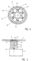
- FIG. 5 Another exemplary embodiment of contactless energy transmission is shown in FIG. 5 shown, the representation essentially the section shown in Fig. 4 IV-IV equivalent.
- the stationary stator 16 consists of a permanent magnet 34, which is surrounded by an iron shell 35.
- the with the drive shaft 20 of the Electric motor 2 rotating rotor 14 has six coils arranged in a ring 32 on, the coil longitudinal axes are aligned radially, so that the end faces of the Coil body 32 each lie approximately parallel to the permanent magnet 34.
- the six coil formers 32 are each reinforced with an induction effect Provided iron core or soft iron core 33, which advantageously one in Fig. 4th has anchored cross-section shown.
- the winding ends of the bobbin 32 are with the circuit board 4 as in the previously described exemplary embodiments or electrically connected to electronic components on the circuit board 4.
- FIG. 5 shows, in a further alternative, the electric motor 2, which is about the supply cable 10 is supplied with electrical energy and by means of Drive shaft 20 drives the circuit board 4 for a rotational movement.
- a primary coil 23 with a magnetic core 24 (iron core, soft iron core) arranged With a small air gap 22 of about up to two millimeters is below the circuit board 4 a primary coil 23 with a magnetic core 24 (iron core, soft iron core) arranged, the coil longitudinal axis approximately at right angles to the circuit board 4th is oriented.
- This primary coil 23 is a secondary coil 25 below Circuit board directly assigned opposite, with the two end faces of the Coils 23 and 25 are approximately parallel to each other.
- This secondary coil 25 can be embedded with a magnetic core 26 in the underside of the circuit board 4.
- the secondary coil 25 can also be on the underside of the circuit board 4 applied or applied in layering technology.
- the inductive energy transmission according to this alternative is carried out by Applying electrical energy to the primary circuit (primary coil) Secondary coil.
Landscapes
- Physics & Mathematics (AREA)
- Engineering & Computer Science (AREA)
- General Physics & Mathematics (AREA)
- Nonlinear Science (AREA)
- Theoretical Computer Science (AREA)
- Chemical & Material Sciences (AREA)
- Power Engineering (AREA)
- Mathematical Physics (AREA)
- Signal Processing (AREA)
- Crystallography & Structural Chemistry (AREA)
- Multimedia (AREA)
- Optics & Photonics (AREA)
- Geometry (AREA)
- Computer Hardware Design (AREA)
- Devices For Indicating Variable Information By Combining Individual Elements (AREA)
- Illuminated Signs And Luminous Advertising (AREA)
- Control Of Indicators Other Than Cathode Ray Tubes (AREA)
- Displays For Variable Information Using Movable Means (AREA)
- Connection Of Motors, Electrical Generators, Mechanical Devices, And The Like (AREA)
Description
- Figur 1
- die Anzeigevorrichtung in ihrem Prinzip-Aufbau im Schnitt entlang der Drehachse der Anordnung;
- Figur 2
- einen Ausschnitt der kontaktlosen Energieübertragung in vergrößerter Darstellung gemäß dem Kreis II von Figur 1;
- Figur 3
- eine Schnittdarstellung des Ausführungsbeispieles von Figur 3 gemäß der Linie IV-IV in Figur 3;
- Figur 4
- eine Alternative des in Figur 3 dargestellten Ausführungsbeispieles in Schnittdarstellung analog der Linie IV-IV in Figur 3; und
- Figur 5
- ein weiteres Ausführungsbeispiel der kontaktlosen Energieübertragung in vereinfachter Darstellung im Schnitt.
- wenn der elektrische Leiter in einem Magnetfeld so bewegt wird, daß er die magnetischen Feldlinien schneidet;
- wenn der elektrische Leiter festgehalten und der Magnet bewegt wird;
- wenn der elektrische Leiter und der Magnet festgehalten, das Magnetfeld aber verändert wird;
- wenn der elektrische Leiter und der Magnet ruhen und bei festem Magnetfeld eine Substanz mit einer anderen relativen Permeabilität in das Magnetfeld eingebracht wird; oder
- wenn der elektrische Leiter verbogen wird.
Claims (7)
- Vorrichtung zur Anzeige von alpha-numerischen Zeichen und/oder Bildzeichen, mit einem Gehäuse (31);
einer in dem Gehäuse (31) drehbar um eine Drehachse (21) angeordneten Anzeigeeinheit, welche einen Träger (5), auf dem zumindest eine Reihe von Leuchtdioden oder Leuchtdioden-Gruppen (6) angeordnet ist, und eine Schaltungsplatine (4) mit einer Ansteuerschaltung für die Leuchtdioden (6) aufweist;
einem Elektromotor (2) zum Drehantrieb der Anzeigeeinheit, wobei die zumindest eine Reihe von Leuchtdioden oder Leuchtdioden-Gruppen (6) im wesentlichen senkrecht zu einer Antriebswelle (20) des Elektromotors (2) bzw. zu der Drehachse der Anzeigeeinheit ausgerichtet ist; und
einer Energie-Übertragungsvorrichtung zur Versorgung der Schaltungsplatine (4) und der Leuchtdioden (6) der Anzeigeeinheit mit elektrischer Energie,
dadurch gekennzeichnet, dass die Versorgung der Schaltungsplatine (4) und der Leuchtdioden (6) der Anzeigeeinheit mit elektrischer Energie kontaktlos und mittels elektromagnetischer Induktion erfolgt; und
dass die Energie-Übertragungsvorrichtung einen von dem Elektromotor (2) angetriebenen Rotor (14), der mit Spulenkörpern (33) mit radial ausgerichteten Längsachsen zur Aufnahme von Spulen (15, 32) versehen ist, deren Spulenenden (13) mit der Anzeigeeinheit verbunden sind, und einen durch einen Permanentmagneten gebildeten ortsfesten Stator (16, 34, 35), der kreisringförmig und im radialen Abstand um den oder in dem Rotor (14) angeordnet ist, aufweist. - Vorrichtung nach Anspruch 1,
dadurch gekennzeichnet, dass der Rotor (14) vier oder sechs Spulenkörper (33) aufweist. - Vorrichtung zur Anzeige von alpha-numerischen Zeichen und/oder Bildzeichen, mit einem Gehäuse (31);
einer in dem Gehäuse (31) drehbar um eine Drehachse (21) angeordneten Anzeigeeinheit, welche einen Träger (5), auf dem zumindest eine Reihe von Leuchtdioden oder Leuchtdioden-Gruppen (6) angeordnet ist, und eine Schaltungsplatine (4) mit einer Ansteuerschaltung für die Leuchtdioden (6) aufweist;
einem Elektromotor (2) zum Drehantrieb der Anzeigeeinheit, wobei die zumindest eine Reihe von Leuchtdioden oder Leuchtdioden-Gruppen (6) im wesentlichen senkrecht zu einer Antriebswelle (20) des Elektromotors (2) bzw. zu der Drehachse der Anzeigeeinheit ausgerichtet ist; und
einer Energie-Übertragungsvorrichtung zur Versorgung der Schaltungsplatine (4) und der Leuchtdioden (6) der Anzeigeeinheit mit elektrischer Energie,
dadurch gekennzeichnet, dass die Versorgung der Schaltungsplatine (4) und der Leuchtdioden (6) der Anzeigeeinheit mit elektrischer Energie kontaktlos und mittels elektromagnetischer Induktion erfolgt; und
dass die Energie-Übertragungsvorrichtung eine auf der Schaltungsplatine (4) angeordnete Sekundärspule (25) und eine auf der Motorabtriebsseite angeordnete und mit elektrischer Energie beaufschlagte Primärspule (23), die der Sekundärspule (25) mit einem geringen Luftspalt gegenüberliegt, aufweist. - Vorrichtung nach Anspruch 3,
dadurch gekennzeichnet, dass die Sekundärspule (25) auf der Schaltungsplatine (4) in Schichttechnik oder als Folie aufgetragen ist. - Vorrichtung nach Anspruch 4,
dadurch gekennzeichnet, dass die Sekundärspule (25) in die Oberfläche der Schaltungsplatine (4) eingesetzt ist. - Vorrichtung nach einem der vorhergehenden Ansprüche,
dadurch gekennzeichnet, dass die Spule(n) (15, 23, 25, 32) einen Eisenkern aufweist bzw. aufweisen. - Vorrichtung nach einem der vorhergehenden Ansprüche,
dadurch gekennzeichnet, dass die Spule(n) (15, 23, 25, 32) in einem Vergusskörper eingebettet ist bzw. sind.
Applications Claiming Priority (3)
| Application Number | Priority Date | Filing Date | Title |
|---|---|---|---|
| DE19702751 | 1997-01-27 | ||
| DE19702751A DE19702751A1 (de) | 1997-01-27 | 1997-01-27 | Vorrichtung zur Anzeige von alpha-numerischen Zeichen und/oder Bildzeichen |
| PCT/EP1998/000284 WO1998033164A1 (de) | 1997-01-27 | 1998-01-20 | Vorrichtung zur anzeige von alpha-numerischen zeichen und/oder bildzeichen |
Publications (2)
| Publication Number | Publication Date |
|---|---|
| EP0954840A1 EP0954840A1 (de) | 1999-11-10 |
| EP0954840B1 true EP0954840B1 (de) | 2002-05-02 |
Family
ID=7818403
Family Applications (1)
| Application Number | Title | Priority Date | Filing Date |
|---|---|---|---|
| EP98904103A Expired - Lifetime EP0954840B1 (de) | 1997-01-27 | 1998-01-20 | Vorrichtung zur anzeige von alpha-numerischen zeichen und/oder bildzeichen |
Country Status (9)
| Country | Link |
|---|---|
| EP (1) | EP0954840B1 (de) |
| JP (1) | JP3338065B2 (de) |
| CN (1) | CN1244940A (de) |
| AT (1) | ATE217114T1 (de) |
| AU (1) | AU6211598A (de) |
| BR (1) | BR9806993A (de) |
| CA (1) | CA2278768A1 (de) |
| DE (2) | DE19702751A1 (de) |
| WO (1) | WO1998033164A1 (de) |
Families Citing this family (12)
| Publication number | Priority date | Publication date | Assignee | Title |
|---|---|---|---|---|
| KR20000005571A (ko) | 1998-06-03 | 2000-01-25 | 유길수 | 문자및/또는영상표시장치및방법 |
| JP4627822B2 (ja) | 1999-06-23 | 2011-02-09 | 株式会社半導体エネルギー研究所 | 表示装置 |
| DE19943047A1 (de) * | 1999-09-09 | 2001-03-15 | Wittenstein Gmbh & Co Kg | Vorrichtung zum Bewegen, insbesondere zum rotativen oder linearen Bewegen einer aktiven Last |
| RU2181507C2 (ru) * | 1999-09-23 | 2002-04-20 | Харченко Сергей Николаевич | Стробоскопическое проекционное устройство |
| US6943762B2 (en) | 2001-02-15 | 2005-09-13 | Newscanner, Plc | Visual message display device |
| US6816137B2 (en) | 2001-02-15 | 2004-11-09 | Newscanner, Plc | Visual message display device |
| KR20030069237A (ko) * | 2002-02-19 | 2003-08-27 | 주식회사 인포기획 | 회전식 정보 표시 장치 |
| DE10228669C1 (de) * | 2002-06-27 | 2003-04-24 | Autoliv Dev | Sicherheitsgurtverschluß mit ausgeleuchteter Bedientaste |
| GB0802553D0 (en) * | 2008-02-12 | 2008-03-19 | Sentec Ltd | Planar rotary data transformer for spinning high definition display system |
| EP2743944B1 (de) * | 2012-12-13 | 2017-02-15 | Tyco Electronics Nederland B.V. | Kontaktloser Steckverbinder |
| CN103632617A (zh) * | 2013-11-30 | 2014-03-12 | 鱼新民 | 全彩立体全方位显示装置 |
| CN110379336B (zh) * | 2019-07-19 | 2021-12-10 | 京东方科技集团股份有限公司 | 一种显示装置及其显示方法 |
Family Cites Families (1)
| Publication number | Priority date | Publication date | Assignee | Title |
|---|---|---|---|---|
| GB8908322D0 (en) * | 1989-04-13 | 1989-06-01 | Stellar Communicat Ltd | Display |
-
1997
- 1997-01-27 DE DE19702751A patent/DE19702751A1/de not_active Withdrawn
-
1998
- 1998-01-20 CA CA002278768A patent/CA2278768A1/en not_active Abandoned
- 1998-01-20 AT AT98904103T patent/ATE217114T1/de not_active IP Right Cessation
- 1998-01-20 BR BR9806993-4A patent/BR9806993A/pt not_active Application Discontinuation
- 1998-01-20 JP JP53156198A patent/JP3338065B2/ja not_active Expired - Fee Related
- 1998-01-20 DE DE59803976T patent/DE59803976D1/de not_active Expired - Lifetime
- 1998-01-20 WO PCT/EP1998/000284 patent/WO1998033164A1/de not_active Ceased
- 1998-01-20 CN CN98802059A patent/CN1244940A/zh active Pending
- 1998-01-20 AU AU62115/98A patent/AU6211598A/en not_active Abandoned
- 1998-01-20 EP EP98904103A patent/EP0954840B1/de not_active Expired - Lifetime
Also Published As
| Publication number | Publication date |
|---|---|
| CA2278768A1 (en) | 1998-07-30 |
| EP0954840A1 (de) | 1999-11-10 |
| JP2000513834A (ja) | 2000-10-17 |
| ATE217114T1 (de) | 2002-05-15 |
| DE19702751A1 (de) | 1998-07-30 |
| CN1244940A (zh) | 2000-02-16 |
| DE59803976D1 (de) | 2002-06-06 |
| WO1998033164A1 (de) | 1998-07-30 |
| JP3338065B2 (ja) | 2002-10-28 |
| AU6211598A (en) | 1998-08-18 |
| BR9806993A (pt) | 2000-03-14 |
Similar Documents
| Publication | Publication Date | Title |
|---|---|---|
| EP0954840B1 (de) | Vorrichtung zur anzeige von alpha-numerischen zeichen und/oder bildzeichen | |
| EP1004110B1 (de) | Vorrichtung zur anzeige von alpha-numerischen zeichen und bildzeichen | |
| DE69011104T2 (de) | Anzeigeeinrichtung. | |
| EP0912971B1 (de) | Anzeigeeinrichtung mit mehreren lichtquellen und anordnung von anzeigeeinrichtungen | |
| DE2730069A1 (de) | Zeitmesser mit einer anzeigeeinrichtung | |
| DE2800886A1 (de) | Gleichstrommotor | |
| DE2622395A1 (de) | Fernablesbarer magnetkompass | |
| DE2804169A1 (de) | Magnetische anzeigeeinrichtung | |
| DE2944246A1 (de) | Zeichengeraet | |
| DE29704397U1 (de) | Vorrichtung zur Anzeige von alpha-numerischen Zeichen und/oder Bildzeichen | |
| DE2646534C3 (de) | Kartengerät | |
| DE3782544T2 (de) | Mit schrittmotoren versehene anzeige. | |
| EP1662637A2 (de) | Elektrische Maschine, insbesondere bürstenloser Gleichstrommotor, und Verfahren zum Justieren einer Sensoreinheit in einer elektrischen Maschine | |
| DE2726948A1 (de) | Kollektorloser gleichstrommotor mit optoelektronischer vorrichtung | |
| WO1999046752A1 (de) | Vorrichtung zur anzeige von alpha-numerischen zeichen und/oder bildzeichen | |
| WO1994010671A1 (de) | Anzeigemodul, für matrixförmige grossflächige anzeigetafeln | |
| DE102024119032A1 (de) | Elektronisches Steuergerät mit variabler Höhe | |
| DE29611155U1 (de) | Vorrichtung zur Anzeige von alpha-numerischen Zeichen und von Bildzeichen | |
| DE19539881A1 (de) | Einrichtung zur Anzeige von Zeichen und Verfahren zu ihrer Herstellung | |
| DE60209119T2 (de) | Einrichtung und verfahren zum ablenken von laserstrahlen | |
| DE2942306A1 (de) | Vorrichtung zum optischen darstellen von informationen | |
| DE102006055925A1 (de) | Bildanzeigeverfahren und -system | |
| DE9313877U1 (de) | Vorrichtung zur Erzeugung von Lichteffekten | |
| DE3403073A1 (de) | Fernsteuerbare anzeigevorrichtung | |
| DE4435462C2 (de) | Rotierende Kopftrommelanordnung |
Legal Events
| Date | Code | Title | Description |
|---|---|---|---|
| PUAI | Public reference made under article 153(3) epc to a published international application that has entered the european phase |
Free format text: ORIGINAL CODE: 0009012 |
|
| 17P | Request for examination filed |
Effective date: 19990624 |
|
| AK | Designated contracting states |
Kind code of ref document: A1 Designated state(s): AT BE CH DE DK ES FI FR GB GR IE IT LI LU NL PT SE |
|
| 17Q | First examination report despatched |
Effective date: 20010509 |
|
| GRAG | Despatch of communication of intention to grant |
Free format text: ORIGINAL CODE: EPIDOS AGRA |
|
| GRAG | Despatch of communication of intention to grant |
Free format text: ORIGINAL CODE: EPIDOS AGRA |
|
| GRAH | Despatch of communication of intention to grant a patent |
Free format text: ORIGINAL CODE: EPIDOS IGRA |
|
| GRAH | Despatch of communication of intention to grant a patent |
Free format text: ORIGINAL CODE: EPIDOS IGRA |
|
| REG | Reference to a national code |
Ref country code: GB Ref legal event code: IF02 |
|
| GRAA | (expected) grant |
Free format text: ORIGINAL CODE: 0009210 |
|
| AK | Designated contracting states |
Kind code of ref document: B1 Designated state(s): AT BE CH DE DK ES FI FR GB GR IE IT LI LU NL PT SE |
|
| PG25 | Lapsed in a contracting state [announced via postgrant information from national office to epo] |
Ref country code: NL Free format text: LAPSE BECAUSE OF FAILURE TO SUBMIT A TRANSLATION OF THE DESCRIPTION OR TO PAY THE FEE WITHIN THE PRESCRIBED TIME-LIMIT Effective date: 20020502 Ref country code: IT Free format text: LAPSE BECAUSE OF FAILURE TO SUBMIT A TRANSLATION OF THE DESCRIPTION OR TO PAY THE FEE WITHIN THE PRE;WARNING: LAPSES OF ITALIAN PATENTS WITH EFFECTIVE DATE BEFORE 2007 MAY HAVE OCCURRED AT ANY TIME BEFORE 2007. THE CORRECT EFFECTIVE DATE MAY BE DIFFERENT FROM THE ONE RECORDED.SCRIBED TIME-LIMIT Effective date: 20020502 Ref country code: IE Free format text: LAPSE BECAUSE OF FAILURE TO SUBMIT A TRANSLATION OF THE DESCRIPTION OR TO PAY THE FEE WITHIN THE PRESCRIBED TIME-LIMIT Effective date: 20020502 Ref country code: GR Free format text: LAPSE BECAUSE OF FAILURE TO SUBMIT A TRANSLATION OF THE DESCRIPTION OR TO PAY THE FEE WITHIN THE PRESCRIBED TIME-LIMIT Effective date: 20020502 Ref country code: GB Free format text: LAPSE BECAUSE OF FAILURE TO SUBMIT A TRANSLATION OF THE DESCRIPTION OR TO PAY THE FEE WITHIN THE PRESCRIBED TIME-LIMIT Effective date: 20020502 Ref country code: FR Free format text: LAPSE BECAUSE OF FAILURE TO SUBMIT A TRANSLATION OF THE DESCRIPTION OR TO PAY THE FEE WITHIN THE PRESCRIBED TIME-LIMIT Effective date: 20020502 Ref country code: FI Free format text: LAPSE BECAUSE OF FAILURE TO SUBMIT A TRANSLATION OF THE DESCRIPTION OR TO PAY THE FEE WITHIN THE PRESCRIBED TIME-LIMIT Effective date: 20020502 |
|
| REF | Corresponds to: |
Ref document number: 217114 Country of ref document: AT Date of ref document: 20020515 Kind code of ref document: T |
|
| REG | Reference to a national code |
Ref country code: GB Ref legal event code: FG4D Free format text: NOT ENGLISH |
|
| REG | Reference to a national code |
Ref country code: CH Ref legal event code: EP |
|
| REF | Corresponds to: |
Ref document number: 59803976 Country of ref document: DE Date of ref document: 20020606 |
|
| REG | Reference to a national code |
Ref country code: IE Ref legal event code: FG4D Free format text: GERMAN |
|
| PG25 | Lapsed in a contracting state [announced via postgrant information from national office to epo] |
Ref country code: SE Free format text: LAPSE BECAUSE OF FAILURE TO SUBMIT A TRANSLATION OF THE DESCRIPTION OR TO PAY THE FEE WITHIN THE PRESCRIBED TIME-LIMIT Effective date: 20020802 Ref country code: PT Free format text: LAPSE BECAUSE OF FAILURE TO SUBMIT A TRANSLATION OF THE DESCRIPTION OR TO PAY THE FEE WITHIN THE PRESCRIBED TIME-LIMIT Effective date: 20020802 Ref country code: DK Free format text: LAPSE BECAUSE OF FAILURE TO SUBMIT A TRANSLATION OF THE DESCRIPTION OR TO PAY THE FEE WITHIN THE PRESCRIBED TIME-LIMIT Effective date: 20020802 |
|
| NLV1 | Nl: lapsed or annulled due to failure to fulfill the requirements of art. 29p and 29m of the patents act | ||
| GBV | Gb: ep patent (uk) treated as always having been void in accordance with gb section 77(7)/1977 [no translation filed] |
Effective date: 20020502 |
|
| PG25 | Lapsed in a contracting state [announced via postgrant information from national office to epo] |
Ref country code: ES Free format text: LAPSE BECAUSE OF FAILURE TO SUBMIT A TRANSLATION OF THE DESCRIPTION OR TO PAY THE FEE WITHIN THE PRESCRIBED TIME-LIMIT Effective date: 20021128 |
|
| REG | Reference to a national code |
Ref country code: IE Ref legal event code: FD4D Ref document number: 0954840E Country of ref document: IE |
|
| EN | Fr: translation not filed | ||
| PG25 | Lapsed in a contracting state [announced via postgrant information from national office to epo] |
Ref country code: LU Free format text: LAPSE BECAUSE OF NON-PAYMENT OF DUE FEES Effective date: 20030120 Ref country code: AT Free format text: LAPSE BECAUSE OF NON-PAYMENT OF DUE FEES Effective date: 20030120 |
|
| PG25 | Lapsed in a contracting state [announced via postgrant information from national office to epo] |
Ref country code: LI Free format text: LAPSE BECAUSE OF NON-PAYMENT OF DUE FEES Effective date: 20030131 Ref country code: CH Free format text: LAPSE BECAUSE OF NON-PAYMENT OF DUE FEES Effective date: 20030131 Ref country code: BE Free format text: LAPSE BECAUSE OF NON-PAYMENT OF DUE FEES Effective date: 20030131 |
|
| PLBE | No opposition filed within time limit |
Free format text: ORIGINAL CODE: 0009261 |
|
| STAA | Information on the status of an ep patent application or granted ep patent |
Free format text: STATUS: NO OPPOSITION FILED WITHIN TIME LIMIT |
|
| 26N | No opposition filed |
Effective date: 20030204 |
|
| REG | Reference to a national code |
Ref country code: CH Ref legal event code: PL |
|
| PGFP | Annual fee paid to national office [announced via postgrant information from national office to epo] |
Ref country code: DE Payment date: 20120118 Year of fee payment: 15 |
|
| PG25 | Lapsed in a contracting state [announced via postgrant information from national office to epo] |
Ref country code: DE Free format text: LAPSE BECAUSE OF NON-PAYMENT OF DUE FEES Effective date: 20130801 |
|
| REG | Reference to a national code |
Ref country code: DE Ref legal event code: R119 Ref document number: 59803976 Country of ref document: DE Effective date: 20130801 |