EP0950835A2 - Drehmomentstütze - Google Patents
Drehmomentstütze Download PDFInfo
- Publication number
- EP0950835A2 EP0950835A2 EP99250111A EP99250111A EP0950835A2 EP 0950835 A2 EP0950835 A2 EP 0950835A2 EP 99250111 A EP99250111 A EP 99250111A EP 99250111 A EP99250111 A EP 99250111A EP 0950835 A2 EP0950835 A2 EP 0950835A2
- Authority
- EP
- European Patent Office
- Prior art keywords
- housing
- base body
- plastic base
- torque support
- support according
- Prior art date
- Legal status (The legal status is an assumption and is not a legal conclusion. Google has not performed a legal analysis and makes no representation as to the accuracy of the status listed.)
- Granted
Links
Images


Classifications
-
- F—MECHANICAL ENGINEERING; LIGHTING; HEATING; WEAPONS; BLASTING
- F16—ENGINEERING ELEMENTS AND UNITS; GENERAL MEASURES FOR PRODUCING AND MAINTAINING EFFECTIVE FUNCTIONING OF MACHINES OR INSTALLATIONS; THERMAL INSULATION IN GENERAL
- F16H—GEARING
- F16H57/00—General details of gearing
- F16H57/02—Gearboxes; Mounting gearing therein
- F16H57/025—Support of gearboxes, e.g. torque arms, or attachment to other devices
-
- Y—GENERAL TAGGING OF NEW TECHNOLOGICAL DEVELOPMENTS; GENERAL TAGGING OF CROSS-SECTIONAL TECHNOLOGIES SPANNING OVER SEVERAL SECTIONS OF THE IPC; TECHNICAL SUBJECTS COVERED BY FORMER USPC CROSS-REFERENCE ART COLLECTIONS [XRACs] AND DIGESTS
- Y10—TECHNICAL SUBJECTS COVERED BY FORMER USPC
- Y10T—TECHNICAL SUBJECTS COVERED BY FORMER US CLASSIFICATION
- Y10T74/00—Machine element or mechanism
- Y10T74/21—Elements
- Y10T74/2186—Gear casings
Definitions
- the invention relates to a torque arm according to the preamble of claim 1.
- a torque arm made of plastic is known between the housing of a wheel block and the housing of a transmission is arranged.
- the torque arm is on one side with the Wheel block housing and on the other side with the gear housing rotatably connected.
- the torque arm has one for attachment to the wheel block housing Flange with holes so that they can be screwed to a corresponding Surface can be attached to the wheel block housing.
- the connection to the gearbox is made via an outer ring formed on the torque arm, the one Has internal teeth.
- An inner ring with a corresponding one is in the ring opening External toothing can be used, which is arranged on the gear housing.
- positive connection is provided by a ring placed around the outer ring Clamping band, through which the outer ring is pressed together.
- the invention has for its object a simple and inexpensive to produce as well as mechanically stable torque arm with a certain elasticity create that is adaptable to almost any transmission pad shape.
- the solution provides that the shell-shaped one-piece plastic body in Injection molding process is produced with support webs arranged inside the shell, that in the plastic body perpendicular to that of the second housing alignable surface aligned bushings are injected that the bushings with Fasteners on the second housing with frictional pressure Can be pressed surface and that the through openings on one flange-like edge region of the plastic base body are formed.
- the Using the injected bushings makes it possible to Fastening screws as fasteners with the permissible torque screw on.
- the desired adhesion is ensured if the bushings do not have the protrude screw head-side contact surface, but at most with this to lock.
- the torque arm can be manufactured very easily, if the sockets with minus tolerance to the contact surface of the screw head side are embedded are. In this way it is ensured that the sockets at most with the Close the contact surface on the screw head flush.
- the manufacturing technology Conditional tolerances ensure that a perfect adhesion without additional effort is ensured.
- the screws can be tightened with great torque if the Bushings are designed as metal cylinder bushes.
- a high strength of the torque support is achieved if the support webs (9) are arranged in a star shape with a cylindrical ring (9a) in the center.
- a uniform distribution of the contact pressure results when in the sockets in the same angular distance from each other and with the same distance to the longitudinal axis of the Cylinder rings are arranged.
- the plastic base body has a constant Wall thickness.
- Fig. 1 shows a spatial representation of a torque arm 1, between a Wheel block housing (first housing of a driven unit) and one Gearbox housing (second housing of a driving unit) is arranged to to support the occurring torques.
- the torque arm 1 has one Plastic base body 2, which is bowl-shaped.
- On the front side of the plastic base body 2 is a contact surface designed as an annular surface 3a 3 trained.
- annular surface 3a 3 trained in the flat circular ring surface 3a, which with their longitudinal axis are aligned perpendicular to the annular surface 3a.
- One of the two end faces 5 of the Bushings 4 are at most flush with the annular surface 3a.
- Fig. 2 shows the torque arm from behind, the shell-like very well Training is recognizable.
- the torque arm is parallel to the annular surface 3a 1 has a flat contact surface 6, which on a flange-like plate-shaped edge 7 is designed in the manner of an outer flange 7a.
- edge 7 outer flange 7a
- injected through openings 8 are provided in the edge 7 (outer flange 7a) injected through openings 8 are provided.
- the contact surfaces 3a and 6 intersect vertically, are on both sides at the same height one through opening 8 each at the same distance from the plane of symmetry arranged.
- Two pairs of such through openings 8 are shown in FIG. 2.
- the top pair is formed by the through openings 8a, etc.
- the im Injection molding plastic body 2 approximately has one constant wall thickness and is additionally with internal support bars 9 Mistake.
- the support webs 9 run in a star shape, with a cylinder ring 9a in Center with which the support webs 9 are connected.
- the torque arm 1 runs through the cylinder ring 9a in the middle Drive shaft.
- the cylinder ring 9a is perpendicular to the contact surfaces 3a, 6 aligned.
- the distance of the sockets 4 from the axis of symmetry of the Cylinder rings 9a are the same for all bushings 4.
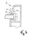
- Fig. 3 shows a cross section through the torque arm 1.
- the bushes 4 are designed and have metal cylinder bushes additionally a radial groove 11 to the position of the injected bushings 4 to to back up.
- the front end that is almost flush with the circular ring surface 3a Bushings 4 are injected into the torque arm 1 with minus tolerance. That is, the Embedding of the bushes 4 takes place so that they do not have the contact surface 4a protrude, but at most close flush with this.
- the sockets 4 a short distance of a maximum of 1/10 millimeters from the contact surface 4a on the screw head side.
- the assembly of the torque arm 1 is usually done so that it with the Annular surface 3a on a corresponding contact surface of a gear housing is attached. Screws are inserted through the sockets 4 and the torque arm 1 screwed onto the gearbox, the screws with the maximum permissible torque can be screwed on without causing a Flow of the plastic comes.
- the sockets 4 ensure a non-positive Connection with the gear housing, the sockets 4 at the same time Press the annular surface 3a against the contact surface of the gearbox. To this A non-positive connection between the plastic base body 2 and the gearbox.
- the torque arm 1 For example, be attached to a wheel block by screws through the Feedthroughs 8 inserted and then screwed tight.
- the drive shaft of the transmission runs through the cylinder ring 9a.
- Angular error between the gear and the wheel block are due to the elasticity of the plastic balanced.
- the plastic also dampens torque peaks that occur. in the In the exemplary embodiment, the torque arm can be rotated in steps of 45 ° be attached.
- FIG. 4 is an enlarged section A of the torque arm according to FIG. 3 with inserted screw shown.
Landscapes
- Engineering & Computer Science (AREA)
- General Engineering & Computer Science (AREA)
- Mechanical Engineering (AREA)
- Gears, Cams (AREA)
- Injection Moulding Of Plastics Or The Like (AREA)
- General Details Of Gearings (AREA)
- Power Steering Mechanism (AREA)
- Agricultural Chemicals And Associated Chemicals (AREA)
- Extraction Or Liquid Replacement (AREA)
Abstract
daß die Durchgangsöffnungen (8) an einem flanschartigen Randbereich (7a) des Kunststoffgrundkörpers (2) ausgebildet sind.
Description
- Fig. 1
- eine räumliche Darstellung einer Drehmomentstütze von vorn gesehen,
- Fig. 2
- die Drehmomentstütze gemäß Fig. 1 von hinten gesehen,
- Fig. 3
- einen Querschnitt durch die Drehmomentstütze gemäß Fig. 1 und
- Fig. 4
- einen vergrößerten Ausschnitt der Drehmomentstütze gemäß Fig. 3.
- 1
- Drehmomentstütze
- 2
- Kunststoffgrundkörper
- 3
- anlegbare Fläche
- 3a
- Kreisringfläche
- 4
- Buchse
- 4a
- (ebene) schraubenkopfseitige Anlagefläche
- 5
- Stirnfläche
- 6
- (ebene) Anlagefläche (Getriebeseite)
- 7
- Rand
- 7a
- Außenflansch
- 8
- Durchgangsöffnung
- 9
- Stützsteg
- 9a
- Zylinderring
- 10
- Längsachse
- 11
- Nut
Claims (9)
- Drehmomentstütze zwischen einem ersten Gehäuse einer angetriebenen Einheit und einem zweiten Gehäuse einer antreibenden Einheit, mit einem jeweils auf einer Seite mit dem ersten Gehäuse und dem zweiten Gehäuse drehfest verbundenen Kunststoffgrundkörper, der zur Befestigung des ersten Gehäuses in einer Ebene liegend eine Anlagefläche mit Durchgangsöffnungen aufweist, wobei an dem Kunststoffgrundkörper ebenfalls in einer Ebene liegend eine weitere an das zweite Gehäuse anlegbare Fläche ausgebildet ist,
dadurch gekennzeichnet,daß der schalenförmige einstückige Kunststoffgrundkörper (2) im Spritzgußverfahren mit innerhalb der Schale angeordneten Stützstegen (9) hergestellt ist,daß in den Kunststoffgrundkörper (2) senkrecht zu der an das zweite Gehäuse anlegbaren Fläche (3) ausgerichtete Buchsen (4) eingespritzt sind,daß die Buchsen (4) mit Befestigungsmitteln am zweiten Gehäuse unter kraftschlüssiger Anpressung der anlegbaren Fläche (3) anpreßbar sind unddaß die Durchgangsöffnungen (8) an einem flanschartigen Randbereich (7a) des Kunststoffgrundkörpers (2) ausgebildet sind. - Drehmomentstütze nach Anspruch 1,
dadurch gekennzeichnet,
daß die Buchsen (4) nicht über die anlegbare Fläche (3) hinausragen, sondern höchstens bündig mit dieser abschließen. - Drehmomentstütze nach Anspruch 1,
dadurch gekennzeichnet,
daß die Buchsen (4) mit Minustoleranz zur schraubenkopfseitigen Anlagefläche (4a) eingebettet sind. - Drehmomentstütze nach einem der Ansprüche 1 bis 3,
dadurch gekennzeichnet,
daß die Buchsen (4) als Metallzylinderbuchsen ausgebildet sind. - Drehmomentstütze nach einem der Ansprüche 1 bis ,
dadurch gekennzeichnet,
daß die anlegbare Fläche (3) eine Kreisringfläche (3a) ist. - Drehmomentstütze nach nach einem der Ansprüche 1 bis 5,
dadurch gekennzeichnet,
daß die Stützstege (9) sternförmig mit einem Zylinderring (9a) im Zentrum angeordnet sind. - Drehmomentstütze nach nach einem der Ansprüche 1 bis 6,
dadurch gekennzeichnet,
daß die Buchsen (4) in gleichem Winkelabstand zueinander und mit gleicher Enffernung zur Längsachse (10) des Zylinderrings (9a) angeordnet sind. - Drehmomentstütze nach einem der Ansprüche 1 bis 7,
dadurch gekennzeichnet,
daß der Kunststoffgrundkörper (2) mit konstanter Wandstärke ausgebildet ist. - Drehmomentstütze nach einem der Ansprüche 1 bis 8,
dadurch gekennzeichnet,
daß die Buchsen (4) eine radiale Nut (11) aufweisen.
Applications Claiming Priority (4)
| Application Number | Priority Date | Filing Date | Title |
|---|---|---|---|
| DE19817931 | 1998-04-17 | ||
| DE19817931 | 1998-04-17 | ||
| DE19825442 | 1998-05-29 | ||
| DE19825442A DE19825442A1 (de) | 1998-04-17 | 1998-05-29 | Drehmomentstütze |
Publications (3)
| Publication Number | Publication Date |
|---|---|
| EP0950835A2 true EP0950835A2 (de) | 1999-10-20 |
| EP0950835A3 EP0950835A3 (de) | 2000-10-04 |
| EP0950835B1 EP0950835B1 (de) | 2002-12-04 |
Family
ID=26045686
Family Applications (1)
| Application Number | Title | Priority Date | Filing Date |
|---|---|---|---|
| EP99250111A Expired - Lifetime EP0950835B1 (de) | 1998-04-17 | 1999-04-09 | Drehmomentstütze |
Country Status (4)
| Country | Link |
|---|---|
| US (1) | US6122995A (de) |
| EP (1) | EP0950835B1 (de) |
| JP (1) | JP4320082B2 (de) |
| ES (1) | ES2185291T3 (de) |
Cited By (1)
| Publication number | Priority date | Publication date | Assignee | Title |
|---|---|---|---|---|
| WO2009040184A3 (de) * | 2007-09-25 | 2009-05-28 | Schaeffler Kg | Schaltdom mit aus kunststoff hergestelltem schaltdeckel |
Families Citing this family (11)
| Publication number | Priority date | Publication date | Assignee | Title |
|---|---|---|---|---|
| DE10047233A1 (de) * | 2000-09-23 | 2002-04-11 | Zahnradfabrik Friedrichshafen | Maschinengehäuse |
| DE10218116B4 (de) * | 2002-04-23 | 2004-04-15 | Siemens Ag | Anordnung aus Kunststoffteil und metallischem Einsatz |
| US6799894B2 (en) * | 2002-06-14 | 2004-10-05 | Anchor Lamina, Inc. | Bushing |
| US7369168B2 (en) | 2003-07-29 | 2008-05-06 | Micron Technology, Inc. | Circuit for an active pixel sensor |
| DE10335014A1 (de) * | 2003-07-31 | 2005-02-24 | Robert Bosch Gmbh | Getriebe-Antriebseinheit |
| JP4472956B2 (ja) * | 2003-08-21 | 2010-06-02 | アスモ株式会社 | モータのギヤハウジング |
| US7152502B2 (en) * | 2003-10-31 | 2006-12-26 | Dana Corporation | Bolted pilot web with precision machined bearing stop |
| US7356901B1 (en) * | 2005-12-20 | 2008-04-15 | Robert Bosch Gmbh | Method of forming bushings between guide pins and guide pin bores |
| DE102008042552A1 (de) * | 2008-10-02 | 2010-04-08 | Robert Bosch Gmbh | Elektropneumatischer Stellungsregler |
| CN103692857A (zh) * | 2013-12-23 | 2014-04-02 | 北京二七轨道交通装备有限责任公司 | 电动轮自卸车用后桥壳及电动轮自卸车 |
| WO2022048769A1 (de) * | 2020-09-04 | 2022-03-10 | Sl-Technik Gmbh | 3-punkt drehmomentstütze |
Family Cites Families (26)
| Publication number | Priority date | Publication date | Assignee | Title |
|---|---|---|---|---|
| US1879287A (en) * | 1928-12-19 | 1932-09-27 | Cleveland Graphite Bronze Co | Steering column bushing |
| US3735645A (en) * | 1971-06-09 | 1973-05-29 | Ferro Mfg Corp | Transmission and housing |
| JPS5773406U (de) * | 1980-10-24 | 1982-05-06 | ||
| JPS584571U (ja) * | 1981-07-01 | 1983-01-12 | 株式会社日立製作所 | クレ−ンサドル |
| US4756632A (en) * | 1984-05-21 | 1988-07-12 | Belanger, Inc. | Plastic bearing |
| DE8606067U1 (de) * | 1986-03-06 | 1986-06-26 | Kupplungstechnik Gmbh, 4440 Rheine | Tragelement für Maschinenaggregate |
| US5152538A (en) * | 1988-03-21 | 1992-10-06 | Chicago Rawhide Manufacturing Company, Inc. | Composite seal assembly |
| JPH0255657A (ja) * | 1988-08-23 | 1990-02-26 | Mitsubishi Motors Corp | セラミック鋳ぐるみ品の鋳造方法 |
| EP0454374B1 (de) * | 1990-04-23 | 1994-12-21 | Tanken Seiko Kabushiki Kaisha | Verfahren zur Vorhersage von Abweichungen in mechanischen Dichtungen und Gerät zu ihrer Vorhersage |
| US5218256A (en) * | 1990-05-31 | 1993-06-08 | Mitsuba Electric Manufacturing Co., Ltd. | Motor casing made of resin |
| DE4021054A1 (de) * | 1990-06-29 | 1992-01-09 | Mannesmann Ag | Drehmomentenstuetze |
| JP2522984Y2 (ja) * | 1990-07-13 | 1997-01-22 | 株式会社三ツ葉電機製作所 | ワイパアームの軸受部構造 |
| DE4025505C3 (de) * | 1990-08-09 | 1997-05-07 | Mannesmann Ag | Getriebegehäuse |
| JPH0743595Y2 (ja) * | 1990-08-31 | 1995-10-09 | いすゞ自動車株式会社 | カバーの取付け装置 |
| FR2669691A1 (fr) * | 1990-11-28 | 1992-05-29 | Ecia Equip Composants Ind Auto | Palier lisse souple et son application aux directions d'automobile. |
| US5401079A (en) * | 1991-08-26 | 1995-03-28 | The Goodyear Tire & Rubber Company | Heat transfer preventing lug hole sleeve inserts for a plastic wheel |
| JPH0542621U (ja) * | 1991-10-31 | 1993-06-11 | 株式会社土屋製作所 | 合成樹脂製ロツカーカバー |
| JP2806193B2 (ja) * | 1993-01-11 | 1998-09-30 | トヨタ自動車株式会社 | 樹脂カバーの締着構造 |
| US5645363A (en) * | 1994-04-15 | 1997-07-08 | Dana Corporation | Bearing cap and pump mounting flange for power take-off unit |
| DE4429102A1 (de) * | 1994-08-17 | 1996-02-22 | Lemfoerder Metallwaren Ag | Radial und axial belastbares Buchsenlager für Fahrwerksteile in Kraftfahrzeugen |
| US5524508A (en) * | 1994-09-19 | 1996-06-11 | Peters; Don | Adapter for coupling an engine and transmission |
| DE29513701U1 (de) * | 1995-08-25 | 1996-09-19 | Siemens AG, 80333 München | Motor-Getriebe-Antriebseinheit, insbesondere Kraftfahrzeug-Fensterheberantrieb o.dgl. |
| US5799548A (en) * | 1996-07-22 | 1998-09-01 | Lexmark International, Inc. | Frame with molded features |
| DE59701253D1 (de) * | 1996-11-06 | 2000-04-20 | Saia Burgess Electronics Ag Mu | Elektroantrieb |
| US5871286A (en) * | 1997-03-27 | 1999-02-16 | Rehrig International, Inc. | Molded wheel and bearing assembly |
| US5984823A (en) * | 1998-08-27 | 1999-11-16 | American Axle & Manufacturing, Inc. | Differential with shaft locking mechanism |
-
1999
- 1999-04-09 ES ES99250111T patent/ES2185291T3/es not_active Expired - Lifetime
- 1999-04-09 EP EP99250111A patent/EP0950835B1/de not_active Expired - Lifetime
- 1999-04-12 JP JP10341999A patent/JP4320082B2/ja not_active Expired - Lifetime
- 1999-04-15 US US09/292,258 patent/US6122995A/en not_active Expired - Lifetime
Cited By (1)
| Publication number | Priority date | Publication date | Assignee | Title |
|---|---|---|---|---|
| WO2009040184A3 (de) * | 2007-09-25 | 2009-05-28 | Schaeffler Kg | Schaltdom mit aus kunststoff hergestelltem schaltdeckel |
Also Published As
| Publication number | Publication date |
|---|---|
| EP0950835A3 (de) | 2000-10-04 |
| JP4320082B2 (ja) | 2009-08-26 |
| US6122995A (en) | 2000-09-26 |
| EP0950835B1 (de) | 2002-12-04 |
| JP2000001103A (ja) | 2000-01-07 |
| ES2185291T3 (es) | 2003-04-16 |
Similar Documents
| Publication | Publication Date | Title |
|---|---|---|
| DE3629198C2 (de) | ||
| EP0349672B1 (de) | Flexible Wellenkupplung mit je einem Anschlussflansch für den Anbau weiterer Kupplungsteile | |
| EP0950835B1 (de) | Drehmomentstütze | |
| DE10060422A1 (de) | Universalgelenk | |
| DE3044415A1 (de) | Elastische kupplung zum uebertragen einer drehbewegung | |
| WO2011054898A1 (de) | Radial einstellbare wellenlageranordnung | |
| DE3219745C2 (de) | Lagerungseinheit für ein angetriebenes Rad eines Kraftfahrzeuges | |
| DE3713870C2 (de) | ||
| DE3817079A1 (de) | Formschluessige verbindung zwischen zwei aus blech bestehenden teilen eines fahrzeuges und verfahren zu ihrer herstellung | |
| DE69203933T2 (de) | Lagerbüchse und Befestigungsschelle für Universalgelenk. | |
| DE102017119775A1 (de) | Elastische Wellenkupplung | |
| EP0318669B1 (de) | Federscheibenkupplung | |
| DE4036367C2 (de) | Scheibenwischerantriebseinrichtung für Kraftfahrzeuge | |
| DE602004002940T2 (de) | Kardangelenk mit haltemechanismus | |
| DE2257903C3 (de) | Ringförmiges, elastisches Element zur Verbindung zweier Kupplungsflansche | |
| EP1360424B1 (de) | Flanschmitnehmer für kreuzgelenke | |
| DE69934429T2 (de) | Verbesserte elastomerbefestigung mit zylindrischer oberflächennabe | |
| DE2422639C2 (de) | Elastische Kupplung | |
| DE19825442A1 (de) | Drehmomentstütze | |
| DE3048340C2 (de) | Winkelbewegliche Gelenkkupplung | |
| EP0984183B1 (de) | Flexible Ganzstahl-Wellen-Kupplung | |
| DE69517779T2 (de) | Elastische Kupplung für drehende Wellen | |
| DE2134318C3 (de) | Verfahren und Anordnung zum Verbinden von Wellenleitern | |
| EP1262693B1 (de) | Schaltschiene mit einer Schaltgabel | |
| EP1360425A1 (de) | Flanschmitnehmer |
Legal Events
| Date | Code | Title | Description |
|---|---|---|---|
| PUAI | Public reference made under article 153(3) epc to a published international application that has entered the european phase |
Free format text: ORIGINAL CODE: 0009012 |
|
| AK | Designated contracting states |
Kind code of ref document: A2 Designated state(s): BE DE ES FR GB IT NL |
|
| AX | Request for extension of the european patent |
Free format text: AL;LT;LV;MK;RO;SI |
|
| PUAL | Search report despatched |
Free format text: ORIGINAL CODE: 0009013 |
|
| AK | Designated contracting states |
Kind code of ref document: A3 Designated state(s): AT BE CH CY DE DK ES FI FR GB GR IE IT LI LU MC NL PT SE |
|
| AX | Request for extension of the european patent |
Free format text: AL;LT;LV;MK;RO;SI |
|
| 17P | Request for examination filed |
Effective date: 20001115 |
|
| AKX | Designation fees paid |
Free format text: BE DE ES FR GB IT NL |
|
| GRAG | Despatch of communication of intention to grant |
Free format text: ORIGINAL CODE: EPIDOS AGRA |
|
| GRAG | Despatch of communication of intention to grant |
Free format text: ORIGINAL CODE: EPIDOS AGRA |
|
| GRAH | Despatch of communication of intention to grant a patent |
Free format text: ORIGINAL CODE: EPIDOS IGRA |
|
| 17Q | First examination report despatched |
Effective date: 20020527 |
|
| RAP1 | Party data changed (applicant data changed or rights of an application transferred) |
Owner name: DEMAG CRANES & COMPONENTS GMBH |
|
| GRAH | Despatch of communication of intention to grant a patent |
Free format text: ORIGINAL CODE: EPIDOS IGRA |
|
| GRAA | (expected) grant |
Free format text: ORIGINAL CODE: 0009210 |
|
| AK | Designated contracting states |
Kind code of ref document: B1 Designated state(s): BE DE ES FR GB IT NL |
|
| REG | Reference to a national code |
Ref country code: GB Ref legal event code: FG4D Free format text: NOT ENGLISH |
|
| GBT | Gb: translation of ep patent filed (gb section 77(6)(a)/1977) |
Effective date: 20021219 |
|
| REF | Corresponds to: |
Ref document number: 59903618 Country of ref document: DE Date of ref document: 20030116 |
|
| ET | Fr: translation filed | ||
| REG | Reference to a national code |
Ref country code: ES Ref legal event code: FG2A Ref document number: 2185291 Country of ref document: ES Kind code of ref document: T3 |
|
| PLBE | No opposition filed within time limit |
Free format text: ORIGINAL CODE: 0009261 |
|
| STAA | Information on the status of an ep patent application or granted ep patent |
Free format text: STATUS: NO OPPOSITION FILED WITHIN TIME LIMIT |
|
| 26N | No opposition filed |
Effective date: 20030905 |
|
| PGFP | Annual fee paid to national office [announced via postgrant information from national office to epo] |
Ref country code: NL Payment date: 20070413 Year of fee payment: 9 |
|
| PGFP | Annual fee paid to national office [announced via postgrant information from national office to epo] |
Ref country code: BE Payment date: 20070502 Year of fee payment: 9 |
|
| BERE | Be: lapsed |
Owner name: *DEMAG CRANES & COMPONENTS G.M.B.H. Effective date: 20080430 |
|
| NLV4 | Nl: lapsed or anulled due to non-payment of the annual fee |
Effective date: 20081101 |
|
| PG25 | Lapsed in a contracting state [announced via postgrant information from national office to epo] |
Ref country code: NL Free format text: LAPSE BECAUSE OF NON-PAYMENT OF DUE FEES Effective date: 20081101 |
|
| PG25 | Lapsed in a contracting state [announced via postgrant information from national office to epo] |
Ref country code: BE Free format text: LAPSE BECAUSE OF NON-PAYMENT OF DUE FEES Effective date: 20080430 |
|
| REG | Reference to a national code |
Ref country code: FR Ref legal event code: PLFP Year of fee payment: 17 |
|
| REG | Reference to a national code |
Ref country code: FR Ref legal event code: PLFP Year of fee payment: 18 |
|
| REG | Reference to a national code |
Ref country code: DE Ref legal event code: R082 Ref document number: 59903618 Country of ref document: DE Representative=s name: MOSER GOETZE & PARTNER PATENTANWAELTE MBB, DE Ref country code: DE Ref legal event code: R081 Ref document number: 59903618 Country of ref document: DE Owner name: TEREX MHPS GMBH, DE Free format text: FORMER OWNER: DEMAG CRANES & COMPONENTS GMBH, 58300 WETTER, DE |
|
| REG | Reference to a national code |
Ref country code: FR Ref legal event code: PLFP Year of fee payment: 19 |
|
| PGFP | Annual fee paid to national office [announced via postgrant information from national office to epo] |
Ref country code: DE Payment date: 20170419 Year of fee payment: 19 Ref country code: GB Payment date: 20170419 Year of fee payment: 19 Ref country code: FR Payment date: 20170419 Year of fee payment: 19 |
|
| PGFP | Annual fee paid to national office [announced via postgrant information from national office to epo] |
Ref country code: IT Payment date: 20170424 Year of fee payment: 19 Ref country code: ES Payment date: 20170517 Year of fee payment: 19 |
|
| REG | Reference to a national code |
Ref country code: DE Ref legal event code: R119 Ref document number: 59903618 Country of ref document: DE |
|
| GBPC | Gb: european patent ceased through non-payment of renewal fee |
Effective date: 20180409 |
|
| PG25 | Lapsed in a contracting state [announced via postgrant information from national office to epo] |
Ref country code: DE Free format text: LAPSE BECAUSE OF NON-PAYMENT OF DUE FEES Effective date: 20181101 |
|
| PG25 | Lapsed in a contracting state [announced via postgrant information from national office to epo] |
Ref country code: GB Free format text: LAPSE BECAUSE OF NON-PAYMENT OF DUE FEES Effective date: 20180409 |
|
| PG25 | Lapsed in a contracting state [announced via postgrant information from national office to epo] |
Ref country code: FR Free format text: LAPSE BECAUSE OF NON-PAYMENT OF DUE FEES Effective date: 20180430 Ref country code: IT Free format text: LAPSE BECAUSE OF NON-PAYMENT OF DUE FEES Effective date: 20180409 |
|
| REG | Reference to a national code |
Ref country code: ES Ref legal event code: FD2A Effective date: 20190911 |
|
| PG25 | Lapsed in a contracting state [announced via postgrant information from national office to epo] |
Ref country code: ES Free format text: LAPSE BECAUSE OF NON-PAYMENT OF DUE FEES Effective date: 20180410 |