EP0950785B1 - Lock fitting with at least two locking bolts for a sliding door, a sliding window or similar - Google Patents
Lock fitting with at least two locking bolts for a sliding door, a sliding window or similar Download PDFInfo
- Publication number
- EP0950785B1 EP0950785B1 EP99400734A EP99400734A EP0950785B1 EP 0950785 B1 EP0950785 B1 EP 0950785B1 EP 99400734 A EP99400734 A EP 99400734A EP 99400734 A EP99400734 A EP 99400734A EP 0950785 B1 EP0950785 B1 EP 0950785B1
- Authority
- EP
- European Patent Office
- Prior art keywords
- chamber
- auxiliary
- front wall
- orifice
- slide bolt
- Prior art date
- Legal status (The legal status is an assumption and is not a legal conclusion. Google has not performed a legal analysis and makes no representation as to the accuracy of the status listed.)
- Expired - Lifetime
Links
Images


Classifications
-
- E—FIXED CONSTRUCTIONS
- E05—LOCKS; KEYS; WINDOW OR DOOR FITTINGS; SAFES
- E05B—LOCKS; ACCESSORIES THEREFOR; HANDCUFFS
- E05B65/00—Locks or fastenings for special use
- E05B65/08—Locks or fastenings for special use for sliding wings
- E05B65/087—Locks or fastenings for special use for sliding wings the bolts sliding parallel to the wings
-
- E—FIXED CONSTRUCTIONS
- E05—LOCKS; KEYS; WINDOW OR DOOR FITTINGS; SAFES
- E05C—BOLTS OR FASTENING DEVICES FOR WINGS, SPECIALLY FOR DOORS OR WINDOWS
- E05C9/00—Arrangements of simultaneously actuated bolts or other securing devices at well-separated positions on the same wing
- E05C9/02—Arrangements of simultaneously actuated bolts or other securing devices at well-separated positions on the same wing with one sliding bar for fastening when moved in one direction and unfastening when moved in opposite direction; with two sliding bars moved in the same direction when fastening or unfastening
- E05C9/026—Arrangements of simultaneously actuated bolts or other securing devices at well-separated positions on the same wing with one sliding bar for fastening when moved in one direction and unfastening when moved in opposite direction; with two sliding bars moved in the same direction when fastening or unfastening comprising key-operated locks, e.g. a lock cylinder to drive auxiliary deadbolts or latch bolts
-
- E—FIXED CONSTRUCTIONS
- E05—LOCKS; KEYS; WINDOW OR DOOR FITTINGS; SAFES
- E05C—BOLTS OR FASTENING DEVICES FOR WINGS, SPECIALLY FOR DOORS OR WINDOWS
- E05C9/00—Arrangements of simultaneously actuated bolts or other securing devices at well-separated positions on the same wing
- E05C9/18—Details of fastening means or of fixed retaining means for the ends of bars
- E05C9/1825—Fastening means
- E05C9/1833—Fastening means performing sliding movements
- E05C9/185—Fastening means performing sliding movements parallel with actuating bar
-
- E—FIXED CONSTRUCTIONS
- E05—LOCKS; KEYS; WINDOW OR DOOR FITTINGS; SAFES
- E05C—BOLTS OR FASTENING DEVICES FOR WINGS, SPECIALLY FOR DOORS OR WINDOWS
- E05C9/00—Arrangements of simultaneously actuated bolts or other securing devices at well-separated positions on the same wing
- E05C9/22—Guides for sliding bars, rods or cables
-
- E—FIXED CONSTRUCTIONS
- E05—LOCKS; KEYS; WINDOW OR DOOR FITTINGS; SAFES
- E05B—LOCKS; ACCESSORIES THEREFOR; HANDCUFFS
- E05B63/00—Locks or fastenings with special structural characteristics
- E05B63/0056—Locks with adjustable or exchangeable lock parts
-
- Y—GENERAL TAGGING OF NEW TECHNOLOGICAL DEVELOPMENTS; GENERAL TAGGING OF CROSS-SECTIONAL TECHNOLOGIES SPANNING OVER SEVERAL SECTIONS OF THE IPC; TECHNICAL SUBJECTS COVERED BY FORMER USPC CROSS-REFERENCE ART COLLECTIONS [XRACs] AND DIGESTS
- Y10—TECHNICAL SUBJECTS COVERED BY FORMER USPC
- Y10T—TECHNICAL SUBJECTS COVERED BY FORMER US CLASSIFICATION
- Y10T292/00—Closure fasteners
- Y10T292/08—Bolts
- Y10T292/0801—Multiple
- Y10T292/0807—Sliding and hooked end
-
- Y—GENERAL TAGGING OF NEW TECHNOLOGICAL DEVELOPMENTS; GENERAL TAGGING OF CROSS-SECTIONAL TECHNOLOGIES SPANNING OVER SEVERAL SECTIONS OF THE IPC; TECHNICAL SUBJECTS COVERED BY FORMER USPC CROSS-REFERENCE ART COLLECTIONS [XRACs] AND DIGESTS
- Y10—TECHNICAL SUBJECTS COVERED BY FORMER USPC
- Y10T—TECHNICAL SUBJECTS COVERED BY FORMER US CLASSIFICATION
- Y10T292/00—Closure fasteners
- Y10T292/08—Bolts
- Y10T292/0911—Hooked end
- Y10T292/0921—Multiple head
Definitions
- the present invention relates to a lock for locking with at least two locking bolts, to sliding door, window, French window or similar.
- the present invention relates to a fitting comprising an assembly sliding which is movable inside and in the longitudinal direction of a profile chamber constituting the front amount of the opening, and which includes a bolt holder, the opening of which is located opposite a first corresponding light formed in the front wall of said chamber, is adapted to receive, if necessary, in an adjustable manner, the tail of a bolt introduced from outside of said chamber.
- each auxiliary bolt is mounted on a mobile support block inside the profile chamber and also driven by a rod movable inside the profile chamber.
- Each support block is held against the wall front of the room by a plate attached to said wall by screws which pass through provided lights in the rod.
- Each plate has a large light dimension for passage and sliding of the block corresponding support.
- each plate for the moving the support block considerably weakens the resistance that said wafer can offer in the event of attempted break-in against the corresponding bolt.
- the object of the present invention is to remedy to the disadvantages of known systems and to propose a locking fitting of the aforementioned type which is robust, reliable, economical, and can be implemented place as well when installing equipment new than during modernization of old equipment any with a minimum of easements and costs.
- the locking fitting of the aforementioned type comprises at least one auxiliary box suitable to be inserted inside the chamber of the profile and to be fixed directly on the face interior of the front wall of said chamber by its front wall which has a light similar to said second corresponding light and which includes means for resting on said inner face around said second light, and in that said auxiliary box has an interior cavity adapted to slidingly receive said bolt holder auxiliary, the interior cavity presenting on its interior surface and auxiliary latch holder having conformations on its outer surface respective complementary extending in the direction longitudinal and in the transverse direction of the front wall of the profile chamber and adapted to cooperate with each other to ensure the guiding the auxiliary bolt holder in the direction longitudinal and maintaining the bolt holder in said cavity.
- the auxiliary box which is fixed directly on the inside of the front wall of the room, can easily be designed to support by itself and transmit in good conditions to the front wall of the profile the forces transmitted to the bolt corresponding assistant in the event of an assault attempt on said bolt.
- the problems of fixing the housing auxiliary against the front wall of the chamber can be adjusted without taking into account the auxiliary bolt holder.
- the auxiliary unit comprises a body having in cross section a section substantially in U-shaped and surrounding an interior cavity, and a cover adapted to be fixed to the body to close substantially said interior cavity after introduction of the auxiliary bolt holder inside said cavity.
- the auxiliary box is thus prepared and prefabricated in advance, which limits the number of components that installers must handle and set up on the installation site of a sliding door.
- the front wall of the body adapted to be fixed against the inner face of the front wall of the chamber is opposite the cover, and the cover has two respective sockets internally threaded adapted to receive screws introduced from outside the chamber through holes in the front wall of said chamber to fix the body against said front wall of said chamber.
- the operating rod is adapted to be introduced inside the chamber and extends parallel to the side faces of the chamber.
- the auxiliary bolt holder has a general shape of an elongated flat rod carrying in protruding on one of its main faces a block of material inside which the opening is made said auxiliary latch holder, and the opening of the latch holder auxiliary leads to a notch in one at least, which acts as the front wall of the housing auxiliary, side walls of the body of said housing.
- this one also relates to an auxiliary box adapted to slidingly receive an auxiliary bolt holder suitable for receiving an auxiliary bolt itself.
- this auxiliary unit is characterized in that it is suitable for equipping a fitting according to the first aspect of the invention.
- FIG. 1 Schematically shown in Figures 1 and 2 a control assembly 1 for a fitting 40 of locking of a sliding leaf, shown diagrammatically in 2, door, window, French window or the like.
- This assembly 1 comprises a sliding assembly 3 which is movable inside and in the direction longitudinal 4 of a chamber 5 of the profile 6 constituting the front upright of the sash 2.
- the sliding assembly 3 comprises a bolt holder 7 whose opening 8, located opposite a first corresponding light 9 formed in the front wall 10 of the chamber 5 constituting the edge of the profile 6, is adapted to receive, if necessary in an adjustable manner, the tail 11 of a bolt 12 introduced from the outside from room 5.
- the sliding assembly 3 slides in direction 4 inside a case 13 which is inserted inside the chamber 5 by a light 14 formed on the inner wall 15 forming the inner facade of profile 6, that is to say the wall facing the interior of the room which is closed by the opening 2.
- the case 13 is secured to a plate of cleanliness 16 which covers the light 14 and which presents itself a light 17 allowing access to an organ maneuver 18 allowing to move the assembly sliding 3 in one direction or the other.
- assembly 1 is fixed to the longitudinal ends of the light 14 by through two fasteners 19 and 20 arranged in such a way that assembly 1 can be snapped onto the edges of the light 14.
- the fastening elements 19 and 20 are by example the fasteners described in the request French Patent No. 97,04065 in the name of the Applicant.
- Assembly 1 could also be subject on the edges of the light 14 through conventional fasteners that you can insert with assembly 1 inside the chamber and which is then subject to the edges longitudinal of light 14 by screws passing through the cleanliness plate 16.
- Assembly 1 can thus be introduced to the interior of chamber 5 by the single light 14 ce which makes it difficult, if not impossible, to unite the sliding assembly 3 with a rod introduced by elsewhere inside said chamber 5.
- the sliding assembly 3 is connected so sliding, by an operating rod 21 extending in the longitudinal direction 4 of the profile 6, to at at least one auxiliary bolt holder 22 whose opening 23, located opposite a second corresponding light 24 formed in the front wall 10 of the chamber 5, is adapted to receive, if necessary in an adjustable manner, the tail 25 of an auxiliary bolt 26.
- the rod 21 is placed outside of chamber 5, in before and near the front wall 10 thereof.
- the rod 21 thus comprises a first hole 27 for the passage of the tail 11 of the bolt 12, and a second hole 28 for the passage of the tail 25 of the auxiliary bolt 26.
- the profile 6 is shaped so that its inner wall 15 and its outer wall 29 each extend in the direction of arrow 30 towards the front beyond the front wall 10 of the chamber 5 by sails 31, 32 which each have a rib 33, 34 extending parallel to the front wall 10 in the longitudinal direction 4 of the profile 6.
- the ribs 33, 34 define guide means adapted to receive the lateral edges 35, 36 of the rod 21 or of all elongate element integral with said rod 21 (see figure 9).
- the following lock fitting 40 the invention comprises in addition to assembly 1 at least an auxiliary box 41 adapted to be introduced to inside chamber 5 of profile 6 and to be fixed directly on the inner face 42 of the front wall 10 of chamber 5 by its front wall 43 which has a light 44 located opposite said second light 24 corresponding and which includes means for build on said inner face 42 around said second light 24.
- the auxiliary unit 41 further comprises a interior cavity 45 adapted to receive so sliding the auxiliary bolt holder 22.
- the inner cavity 45 present on its inner surface
- the auxiliary bolt holder 22 present on its surface exterior, respective conformations complementary 46, 47 extending in the direction longitudinal 4 and in transverse direction 48 of the front wall 10 of the chamber 5 of the profile 6 and adapted to cooperate with each other to guiding the auxiliary bolt holder 22 in the longitudinal direction 4 and holding the bolt holder 22 in said interior cavity 45.
- the auxiliary housing 41 comprises a body 49 having in cross section a section substantially U-shaped and surrounding said cavity interior 45 and a cover 50 adapted to be fixed to the body 49 for substantially closing said cavity interior 45 after introduction of the bolt holder auxiliary 22 inside said cavity 45.
- the operating rod 21 is adapted to be slidingly attached to the outside of the chamber 5 due profile 6, between the front wall 10 and the ribs longitudinal 33, and 34 of profile 6.
- the cover 50 has two respective sockets 51 projecting from the side of the body 50 along it.
- Sockets 51 are internally threaded and are suitable for receiving screws 52 introduced from outside the chamber 5 to through holes 53 in the front wall 10 of said chamber 5 for fixing the body 49 against said wall before 10 of said chamber 5.
- the cover 50 presses the body 49 and in particular the front wall 43 thereof against the inner face 42 of the wall before 10.
- the body 49 and the cover 50 include respective means 57, 58 complementary to each other can snap the cover 50 onto the body 49.
- the cover 50 has two legs elastic bands 58 each carrying a protruding lug 58a suitable for engaging with a complementary lug 57a corresponding to a lug 57 of the body 49 of the housing 41.
- the front wall 43 of the auxiliary housing 41 includes a central region 59 projecting toward the exterior, of exterior contour corresponding to the inner outline of the second light 24 to make protrudes through said lumen 24, and, on either side other of said region 59, two shoulders 60 extending in the longitudinal direction 4 of the profile 6 and adapted to bear against the inner face 42 of the front wall 10 of the profile 6.
- the auxiliary unit 41 can be inserted in chamber 5 of profile 6 through a light located anywhere on the front wall 10 profile 6, and be moved in chamber 5 to what it looks like in front of the light 24.
- At least one of the screws 52 for fixing the housing auxiliary 41 on the front wall 10 can be a screw needle 52a adapted to bear on the face interior 61 of the rear wall 62 of the chamber 5 of the profile 6.
- the needle screw 52a presses the cover 50 against the body 49 of the auxiliary unit 41, and said body 49 against the inner face 42 of the front wall 10 of profile 6, bearing on the rear wall 62 of chamber 5, while an ordinary screw 52 with head milled is supported on the front wall 10 of said profile 6 for the same function.
- the auxiliary box 41 is fixed by two needle screws 52a, and the central region 59 of the front wall 43 includes the two legs 55.
- the needle screws 52a are introduced by light 24.
- the screw shown at the bottom of these two Figures is a needle screw 52a bearing against the rear wall 62 of chamber 5.
- the screw located in the part upper of these two figures is a conventional screw 52 with countersunk head which passes through a hole 53 in the front wall 10 and a hole 54 in the corresponding tab 55 which is shaped to fit under the front wall 10 to the transverse edge 56 of the light 24.
- the auxiliary box 41 present, preferably on its cover 50, lateral elastic tabs 63 for lean on the side walls 64, 65 of the chamber 5 in order to center the auxiliary box 41 in the transverse direction 48 of the front wall 10 to inside the room 5.
- the cover 50 of the auxiliary box 41 advantageously also has legs rear elastic 66 to rest on the wall rear 62 of room 5.
- auxiliary boxes 41 can be easily placed inside the room either when installing the sliding sash corresponding with its fitting, either during the transformation of an existing fitting to equip it with several auxiliary bolts to strengthen the resistance of this fitting in the event of an attempt burglary.
- Profile 6 does not need to have the structure shown in Figures 7 to 9.
- the operating rod 21 driven by the main bolt 12 can cause the auxiliary bolts 26 integral with their bolt holder respective auxiliary 22.
- the forces transmitted to the auxiliary bolts 26 are absorbed by the auxiliary unit 41 corresponding and retransmitted by it either to the wall front 10 alone, or at the same time at the front wall 10 and to the rear wall 62 of the profile.
- the conformations 46 of the interior surface of the cavity 45 are formed by two shoulders 46 arranged in transverse direction 48 and extending in the longitudinal direction 4 of the profile 6.
- the conformations 47 of the external surface of the bolt holder 22 are made up of complementary shoulders 47 arranged in the same transverse direction 48 and extending in the same longitudinal direction 4.
- the auxiliary bolt holder 22 has a rib 67 projecting in transverse direction 48 and extending in the longitudinal direction 4. This rib 67 is adapted to penetrate a groove corresponding 67a formed in the inner wall of cavity 45.
- Figures 3 to 6 and 19 show a auxiliary bolt holder 22 whose opening 23 has a shape general rectangular provided for the passage of the tail 25 of the auxiliary bolt 26.
- the opening 23 has in addition, in the middle of one of its large edges, a hole substantially semi-cylindrical 68 threaded for passage a screw for adjusting the position of the tail 25 of the bolt 26 inside the opening 23.
- the opening 23 opens on both sides of the auxiliary latch holder 22,
- light 44 of the wall front 43 of the auxiliary unit 41 has a general shape rectangular allowing access to the adjustment screw bolt in all possible positions of the bolt holder 22 with respect to the housing 41, with two extensions longitudinal 69 for the passage of the tail 25.
- the length, in the longitudinal direction 4, of the light 44, extensions 69 included, is at least equal to the sum of the width C of the tail 25 of the bolt 26 and of the stroke D of said bolt (see FIG. 4).
- the light 24 formed in the front wall 10 a at least the dimensions of the light. 44, and is here shaped to allow the central region 59 of the front wall 43 to protrude into this light for immobilize with force the auxiliary unit 41 on the front wall 10 in cooperation with the screws 52, 52a.
- the cover 50 also has a light 44 for the possible passage of the free end of a tail bolt too long.
- FIGS. 20 to 29 show a mode of production of a multiple locking fitting 70 bolts according to the invention in which the rod of maneuver 71 is adapted to be introduced inside of chamber 5 and extends parallel to the walls side 64, 65 of chamber 5.
- the bolt holder auxiliary 72 has the general shape of an elongated rod flat parallel to the rod 71 and projecting door on one of its main faces a block 73 of material to the interior of which is formed the opening 74 of said auxiliary latch holder 72.
- the opening 74 of the auxiliary bolt holder 72 leads to a notch 75 of at least one, which acts as the front wall 76 of the auxiliary box 77, front or rear walls 76, 78 of the body 79 of said box 77.
- the auxiliary unit 77 has a plane of symmetry 80, at least for its external configuration, so that each of the two walls 76, 78 has a notch 75 adapted to receive the tail 25 of an auxiliary bolt 26.
- the body 79 of the auxiliary box 77 comprises at least two regions 81 in each of which is provided a tapped hole 82 adapted to receive a corresponding screw 83 for fixing the auxiliary box 77 to the front wall 10 of chamber 5 of profile 6.
- Each of the regions 81 has a means 84 in projection, for example a riveting element, suitable for pass through a groove 85 of the bolt holder 72 and to cooperate with a corresponding hole 86 of the cover 87 for the fixing said cover 87 to the body 79 of the housing auxiliary 77 after introduction of the bolt holder 72 to the interior of the interior cavity 88 of the housing 77.
- a means 84 in projection for example a riveting element
- the auxiliary box 77 presents to each of its longitudinal ends an opening 89 for the passage of one end 90 of the auxiliary bolt holder 72 shaped so that it can be connected to a rod of operation 71.
- the opening 89 has a flattened section and is formed between the corresponding region 81 and the cover 87.
- each of the ends 90 of the auxiliary latch holder 72 has a flattened part 91 passing through the opening 89 and having the groove 85, extended outward by at least one tab 92 provided with a hole 93 for fixing the end of a rod 71 for example by means of a screw.
- Each flattened part 91 has a length at least equal to the stroke of the bolt holder.
- the auxiliary bolt holder 72 comprises the projecting block 73 described above, as well as a ratchet of positioning similar to that of the assembly of command (see below).
- the end 90 has preferably two legs 92 between which comes insert the end of the rod 71.
- the auxiliary box 77 is practically necessarily introduced inside chamber 5 by one end of it. At time the introduction of the auxiliary box 77 into the chamber 5, the bolt holder 72 is already fixed to the rods 71 corresponding.
- box 77 If the box 77 is connected to another box auxiliary, the latter will be fixed to the rod 71 before its introduction inside the room.
- the housing 77 is equipped with Figure 24 of a spring 77a for adaptation to a chamber 5 of great width in the transverse direction 48.
- the locking fitting 70 comprises an assembly of control consisting of a main box 95 adapted to be inserted inside chamber 5 of the profile 6 by a corresponding light 14 formed in the side wall of chamber 5 and profile 6 constituting the wall and interior facade 15 of the sliding leaf 2, and a cover 96 adapted to close off an identical light 97 formed on the other wall 29 of chamber 5.
- the cover 96 has on its face interior two conformations 98 each comprising a tapped hole 99 suitable for receiving a screw 100 for the fixing the main box 95 and the cover 96 to the profile 6 of the sliding leaf 2.
- the main box 95 is a cross section profile substantially in the form of U of which each of the side walls 101, 102 has its edge respective exterior 103, 104 folded down substantially at right angle to the other side wall 102, 101 for guide the sliding assembly 94.
- the sliding assembly 94 shown in the figures 20 and 21 is known. It includes, in particular, a operating member 105, a pawl 106 adapted to rock against the action of springs so that keep the sliding assembly 94 stably in each of its extreme positions and an organ anti-false operation 107 of which a feeler finger 107c is adapted to bear against a wall 107a of the keeper 107b to move said member 107 and authorize a sliding of the sliding assembly 94 from the position open in the locked position of figure 20.
- the known sliding assembly 94 has been modified and shaped so as to include, at its end longitudinal 108 shown in the upper part Figures 20 and 21, a light 109 for the passage of the corresponding screw 100 for fixing the housing main 94, and a tab 110 pierced with a hole 111 for connect this tab 110 to a rod 71 by a means of fixing, for example by a screw or a rivet 112.
- the screw 112 can be put in place through the light 97 while the main box 95 is only partially introduced into light 14 corresponding.
- the sliding assembly 94 comprises at its other longitudinal end 113 of the stop means 114 adapted to receive, when the main box 95 is completely introduced into the light 14 corresponding, complementary stop means 115 formed at the end 116 of a second rod 71 for allow the sliding assembly 94 to drive said second rod 71 in its sliding movements in both directions, and means to block them complementary stop means 115 in their position in engagement with the stop means 114 of the assembly sliding 94.
- the means for blocking the complementary stop means 115 in their position in engagement with the stop means 114 of the end 113 are movable means relative to the sliding assembly 94 and adapted to be actuated from outside bedroom 5 through the light 97 can be closed off by the cover 95.
- the sliding assembly 94 has a removable plate 118 shaped so to allow the movement of the assembly to be controlled sliding 94 from the outside of the opening 2 by means a key 119 actuating a cylinder 120 of lock 121 at the end of which is fixed a disc 122 carrying a eccentric finger 123 extending axially.
- the plate 118 has two transverse walls 124, 125 between which the finger 123 can penetrate when the disc 122 rotates in a either way to move plate 118 in the corresponding longitudinal direction.
- the walls 124 and 125 extend over a part only of the width of the plate 118 to release the bottom 126 of said plate 118 to allow free movement of finger 123 during rotation of the disc 122 before and after moving the plate 118.
- the end 116 of the rod 71 has two tabs 127 adapted to extend and slide from on either side of the corresponding fixing screw 100 of the main housing 95.
- Each tab 127 comprises at its free end an element 128 projecting towards the outside adapted to engage with a notch complementary 129 of a side wing 130 corresponding to the sliding assembly 94.
- the plate removable 118 blocks each tab 127 in its engaged position in which the protruding member 128 is engaged in the corresponding notch 129.
- the plaque removable 118 present on its bottom 126 in contact with the bottom 131 of the sliding assembly 94 an opening 132 allowing the passage of a stud 117 pivotally mounted around a finger 133 fixed to the bottom 131 of the assembly sliding.
- the opening 132 of the bottom 126 of the plate 117 with a thinned edge 134 so as to allow pivoting pin 117 around finger 132 to block said edge thinned 134 and therefore the plate 118 on the bottom 131 of the sliding assembly 94.
- the plate 118 has at in addition to a longitudinal projection 135 which is inserted between the two tabs 127 to immobilize the element 128 protruding into the notches 129 and therefore immobilize the tongues relative to the assembly sliding 94.
- connections between the rod 71 and the assembly slide 94 which we have just described are mobile links which facilitate the introduction of elements inside profile 6 by the end of the latter, in particular allowing a break angular at each link.
- connection by the screw 111, in the part upper of Figures 20 and 21, or the connection by claws 128 of the tabs 127 which are housed in the notches 129, allow easy connection, fast and flexible with the sliding assembly 94.
- auxiliary boxes and auxiliary latch holders described above can be used with sliding assemblies and control assemblies different from those described.
Abstract
Description
La présente invention concerne une serrure de verrouillage à au moins deux pênes de condamnation, pour ouvrant coulissant de porte, fenêtre, porte-fenêtre ou analogue.The present invention relates to a lock for locking with at least two locking bolts, to sliding door, window, French window or similar.
De façon plus particulière, la présente invention concerne une ferrure comportant un ensemble coulissant qui est mobile à l'intérieur et dans la direction longitudinale d'une chambre du profilé constituant le montant avant de l'ouvrant, et qui comprend un porte-pêne dont l'ouverture , située en face d'une première lumière correspondante ménagée dans la paroi avant de ladite chambré, est adaptée à recevoir, le cas échéant, de manière réglable, la queue d'un pêne introduite depuis l'extérieur de ladite chambre.More specifically, the present invention relates to a fitting comprising an assembly sliding which is movable inside and in the longitudinal direction of a profile chamber constituting the front amount of the opening, and which includes a bolt holder, the opening of which is located opposite a first corresponding light formed in the front wall of said chamber, is adapted to receive, if necessary, in an adjustable manner, the tail of a bolt introduced from outside of said chamber.
On sait fixer à l'extrémité inférieure de cet ensemble coulissant une tringle adaptée à venir en prise avec une gâche ménagée dans le profilé servant de traverse inférieure sur laquelle coulisse l'ouvrant coulissant. Lorsque l'on fait coulisser l'ensemble coulissant vers le bas pour verrouiller l'ouvrant au moyen du pêne de l'ensemble coulissant, l'extrémité libre de la tringle vient en prise avec la gâche correspondante pour compléter ce verrouillage.We know how to fix at the lower end of this sliding assembly a rod adapted to engage with a keeper in the profile serving as lower cross member on which the sash slides sliding. When we slide the whole thing sliding down to lock the sash at the bolt of the sliding assembly, the end free of rod comes into contact with striker corresponding to complete this locking.
Toutefois, il suffit de soulever l'ouvrant pour libérer la tringle et le pêne de leur gâche respective. Les impératifs croissants en matière de sécurité des ouvrants coulissants font qu'il existe un besoin pour des ferrures de verrouillage pour ouvrant coulissant comportant au moins deux pênes de condamnation.However, it is enough to lift the sash to release the rod and the bolt from their respective keepers. Growing security imperatives sliding doors that there is a need for locking fittings for sash sliding comprising at least two bolts of conviction.
Ce besoin concerne aussi bien les installations neuves, qu'il convient d'équiper dès leur mise en place du nombre requis de pênes, que des installations anciennes qu'il s'agit de moderniser en les équipant, de façon aussi simple et économique que possible, de pênes auxiliaires.This need concerns both installations new ones, which should be fitted as soon as they are installed of the required number of bolts, only installations to modernize by equipping them, as simple and economical as possible, with bolts Auxiliary.
On connaít, d'après le EP-A-0 757 146, une ferrure de verrouillage du type précité dans laquelle l'ensemble coulissant est relié de manière coulissante, par une tringle de manoeuvre s'étendant dans la direction longitudinale du profilé, à au moins un porte-pêne auxiliaire dont l'ouverture, située en face d'une seconde lumière correspondante ménagée dans la paroi avant de la chambre, est adaptée à recevoir, le cas échéant de manière réglable, la queue d'un pêne auxiliaire.We know, from EP-A-0 757 146, a locking fitting of the aforementioned type in which the sliding assembly is slidably connected, by an operating rod extending in the longitudinal direction of the profile, at least one latch holder auxiliary whose opening, located opposite a second corresponding light in the wall front of the room, is suitable to receive, if if necessary adjustable, the tail of a bolt auxiliary.
Selon ce document, chaque pêne auxiliaire est monté sur un bloc support mobile à l'intérieur de la chambre du profilé et entraíné par une tringle également mobile à l'intérieur de la chambre du profilé.According to this document, each auxiliary bolt is mounted on a mobile support block inside the profile chamber and also driven by a rod movable inside the profile chamber.
Chaque bloc support est retenu contre la paroi avant de la chambre par une plaquette fixée à ladite paroi par des vis qui traversent des lumières ménagées dans la tringle.Each support block is held against the wall front of the room by a plate attached to said wall by screws which pass through provided lights in the rod.
Chaque plaquette présente une lumière de grande dimension pour le passage et le coulissement du bloc support correspondant.Each plate has a large light dimension for passage and sliding of the block corresponding support.
La lumière ménagée dans chaque plaquette pour le déplacement du bloc support affaiblit considérablement la résistance que ladite plaquette peut offrir en cas de tentative d'effraction contre le pêne correspondant.The light provided in each plate for the moving the support block considerably weakens the resistance that said wafer can offer in the event of attempted break-in against the corresponding bolt.
En outre, tous les éléments constituant cette serrure doivent être introduits dans la chambre à une extrémité du profilé, ce qui exige des manutentions importantes et rend difficile la fixation des plaquettes contre la paroi avant de la chambre.In addition, all the elements constituting this lock must be introduced into the room at a end of the profile, which requires handling important and makes it difficult to attach the pads against the front wall of the chamber.
Le but de la présente invention est de remédier aux inconvénients des systèmes connus et de proposer une ferrure de verrouillage du type précité qui soit robuste, fiable, économique, et qui puisse être mise en place aussi bien lors de l'installation d'un équipement neuf que lors d'une modernisation d'un équipement ancien quelconque avec un minimum de servitudes et de frais.The object of the present invention is to remedy to the disadvantages of known systems and to propose a locking fitting of the aforementioned type which is robust, reliable, economical, and can be implemented place as well when installing equipment new than during modernization of old equipment any with a minimum of easements and costs.
Suivant l'invention, la ferrure de verrouillage du type précité comporte au moins un boítier auxiliaire adapté à être introduit à l'intérieur de la chambre du profilé et à être fixé directement sur la face intérieure de la paroi avant de ladite chambre par sa paroi avant qui présente une lumière semblable à ladite seconde lumière correspondante et qui comporte des moyens pour prendre appui sur ladite face intérieure autour de ladite seconde lumière, et en ce que ledit boítier auxiliaire comporte une cavité intérieure adaptée à recevoir de manière coulissante ledit porte-pêne auxiliaire, la cavité intérieure présentant sur sa surface intérieure et le porte-pêne auxiliaire présentant sur sa surface extérieure des conformations respectives complémentaires s'étendant dans la direction longitudinale et dans la direction transversale de la paroi avant de la chambre du profilé et adaptées à coopérer les unes avec les autres pour assurer le guidage du porte-pêne auxiliaire dans la direction longitudinale et le maintien du porte-pêne dans ladite cavité.According to the invention, the locking fitting of the aforementioned type comprises at least one auxiliary box suitable to be inserted inside the chamber of the profile and to be fixed directly on the face interior of the front wall of said chamber by its front wall which has a light similar to said second corresponding light and which includes means for resting on said inner face around said second light, and in that said auxiliary box has an interior cavity adapted to slidingly receive said bolt holder auxiliary, the interior cavity presenting on its interior surface and auxiliary latch holder having conformations on its outer surface respective complementary extending in the direction longitudinal and in the transverse direction of the front wall of the profile chamber and adapted to cooperate with each other to ensure the guiding the auxiliary bolt holder in the direction longitudinal and maintaining the bolt holder in said cavity.
Ainsi, le boítier auxiliaire, qui est fixé directement sur la face intérieure de la paroi avant de la chambre, peut facilement être conçu pour supporter par lui-même et transmettre dans de bonnes conditions à la paroi avant du profilé les efforts transmis au pêne auxiliaire correspondant en cas de tentative d'agression sur ledit pêne.Thus, the auxiliary box, which is fixed directly on the inside of the front wall of the room, can easily be designed to support by itself and transmit in good conditions to the front wall of the profile the forces transmitted to the bolt corresponding assistant in the event of an assault attempt on said bolt.
En outre, les problèmes de fixation du boítier auxiliaire contre la paroi avant de la chambre peuvent être réglés sans tenir compte du porte-pêne auxiliaire. In addition, the problems of fixing the housing auxiliary against the front wall of the chamber can be adjusted without taking into account the auxiliary bolt holder.
Parallèlement, les problèmes de guidage et de maintien du porte-pêne auxiliaire dans la cavité du boítier auxiliaire correspondant peuvent être résolus sans avoir à tenir compte des problèmes de fixation du boítier auxiliaire contre la paroi avant.At the same time, the problems of guidance and maintaining the auxiliary bolt holder in the cavity of the corresponding auxiliary box can be solved without having to take into account the problems of fixing the auxiliary box against the front wall.
Suivant une version avantageuse de la l'invention, le boítier auxiliaire comporte un corps ayant en coupe transversale une section sensiblement en forme de U et entourant une cavité intérieure, et un couvercle adapté à être fixé au corps pour fermer sensiblement ladite cavité intérieure après introduction du porte-pêne auxiliaire à l'intérieur de ladite cavité.According to an advantageous version of the the invention, the auxiliary unit comprises a body having in cross section a section substantially in U-shaped and surrounding an interior cavity, and a cover adapted to be fixed to the body to close substantially said interior cavity after introduction of the auxiliary bolt holder inside said cavity.
Le boítier auxiliaire est ainsi préparé et préfabriqué à l'avance, ce qui limite le nombre de composants que les installateurs doivent manipuler et mettre en place sur le chantier d'installation d'un ouvrant coulissant.The auxiliary box is thus prepared and prefabricated in advance, which limits the number of components that installers must handle and set up on the installation site of a sliding door.
Suivant une version intéressante de l'invention, et la tringle de manoeuvre étant adaptée à être fixée de manière coulissante à l'extérieur et à proximité de la paroi avant de la chambre du profilé, la paroi avant du corps adaptée à être fixée contre la face intérieure de la paroi avant de la chambre est opposée au couvercle, et le couvercle présente deux douilles respectives filetées intérieurement adaptées à recevoir des vis introduites par l'extérieur de la chambre à travers des trous de la paroi avant de ladite chambre pour fixer le corps contre ladite paroi avant de ladite chambre.According to an interesting version of the invention, and the operating rod being adapted to be fixed from sliding way outside and near the front wall of the profile chamber, the front wall of the body adapted to be fixed against the inner face of the front wall of the chamber is opposite the cover, and the cover has two respective sockets internally threaded adapted to receive screws introduced from outside the chamber through holes in the front wall of said chamber to fix the body against said front wall of said chamber.
On peut ainsi résoudre très simplement le problème de la fixation du boítier auxiliaire sur la paroi avant de la chambre sans avoir à tenir compte des conditions d'entraínement du pêne auxiliaire et du porte-pêne correspondant par la tringle extérieure.We can thus very simply resolve the problem of fixing the auxiliary box on the front wall of the room without having to take into account conditions for driving the auxiliary bolt and corresponding latch holder by the external rod.
Suivant une autre version intéressante de l'invention, la tringle de manoeuvre est adaptée à être introduite à l'intérieur de la chambre et s'étend parallèlement aux faces latérales de la chambre.Next another interesting version of the invention, the operating rod is adapted to be introduced inside the chamber and extends parallel to the side faces of the chamber.
Dans ces conditions, le porte-pêne auxiliaire a une forme générale de tringle allongée plate portant en saillie sur une de ses faces principales un bloc de matière à l'intérieur duquel est ménagée l'ouverture dudit porte-pêne auxiliaire, et l'ouverture du porte-pêne auxiliaire débouche devant une échancrure de l'une au moins, qui fait office de paroi avant du boítier auxiliaire, des parois latérales du corps dudit boítier.Under these conditions, the auxiliary bolt holder has a general shape of an elongated flat rod carrying in protruding on one of its main faces a block of material inside which the opening is made said auxiliary latch holder, and the opening of the latch holder auxiliary leads to a notch in one at least, which acts as the front wall of the housing auxiliary, side walls of the body of said housing.
Suivant un autre aspect de l'invention celle-ci concerne également un boítier auxiliaire adapté à recevoir de manière coulissante un porte-pêne auxiliaire apte à recevoir lui-même un pêne auxiliaire.According to another aspect of the invention, this one also relates to an auxiliary box adapted to slidingly receive an auxiliary bolt holder suitable for receiving an auxiliary bolt itself.
Suivant l'invention, ce boítier auxiliaire est caractérisé en ce qu'il est adapté à équiper une ferrure de verrouillage selon le premier aspect de l'invention.According to the invention, this auxiliary unit is characterized in that it is suitable for equipping a fitting according to the first aspect of the invention.
D'autres particularités et avantages de la présente invention apparaítront dans la description détaillée ci-après.Other features and advantages of the present invention will appear in the description detailed below.
Aux dessins annexés, donnés uniquement à titre d'exemples non limitatifs :
- la figure 1 est une vue partielle en élévation de la paroi formant la façade intérieure d'un ouvrant coulissant équipée d'un assemblage de commande selon un premier mode de réalisation d'une ferrure de verrouillage selon la présente invention ;
- la figure 2 est une vue de côté, avec arrachement, prise depuis la gauche de la figure 1, illustrant un mode de réalisation de l'assemblage de commande schématisé à ladite figure 1 ;
- la figure 3 est une vue agrandie, semblable à la figure 1, illustrant un mode de réalisation d'un boítier auxiliaire d'une ferrure de verrouillage selon la présente invention ;
- la figure 4 est une vue partielle, semblable à la figure 3, d'un autre mode de réalisation d'un boítier auxiliaire selon la présente invention ;
- la figure 5 est une vue prise depuis la gauche de la figure 3, le pêne et la tringle ayant été retirés pour la clarté de la figure, le porte-pêne étant dans une première position ;
- la figure 6 est une vue semblable à la figure 5 et correspondant à la figure 4, le porte-pêne étant dans son autre position ;
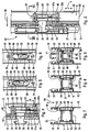
- la figure 7 est une vue partielle en coupe suivant VII-VII à la figure 3, le profilé étant représenté seul ;
- la figure 8 est une vue semblable à la figure 7, le boítier auxiliaire étant en place dans la chambre du profilé ;
- la figure 9 est une vue semblable à la figure 8, montrant également la tringle de manoeuvre et la gâche ;
- la figure 10 est une vue en perspective d'un mode de réalisation du boítier auxiliaire représenté aux figures 3 à 6 et 8 et 9 ;
- la figure 11 est une vue de dessus du couvercle du boítier auxiliaire de la figure 10 ;
- la figure 12 est une vue en coupe selon XII-XII à la figure 11 ;
- la figure 13 est une vue de dessus du corps du boítier auxiliaire de la figure 10 ;
- la figure 14 est une vue de dessous dù corps de la figure 13 ;
- la figure 15 est une vue en coupe selon XV-XV à la figure 13 ;
- la figure 16 est une vue en coupe suivant XVI-XVI à la figure 13 ;
- la figure 17 est une vue de dessus du porte-pêne auxiliaire adapté à coulisser à l'intérieur du boítier auxiliaire des figures 10 à 16 ;
- la figure 18 est une vue en élévation du porte-pêne de la figure 17 vu depuis la droite de cette figure ;
- la figure 19 est une vue en coupe selon XIX-XIX à la figure 17 ;
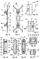
- la figure 20 est une vue semblable à la figure 1, avec arrachement, d'un autre mode de réalisation d'un assemblage de commande d'une ferrure de verrouillage selon la présenteinvention ;
- la figure 21 est une vue en élévation, avec arrachement, de l'assemblage de la figure 20 vu depuis la gauche de cette figure ;
- la figure 22 est une vue partielle d'un détail de la figure 20 ;
- la figure 23 est une vue semblable à la figure 20 représentant un mode de réalisation d'un boítier auxiliaire selon la présente invention adapté à être monté avec l'assemblage de commande de la figure 20 ;
- la figure 24 est une vue semblable à la figure 21 du boítier auxiliaire de la figure 23 ;
- la figure 25 est une vue partielle agrandie, avec arrachement, représentant le boítier auxiliaire des figures 23 et 24 vu depuis l'arrière de la figure 23 ;
- la figure 26 est une vue, avec arrachement, du boítier auxiliaire de la figure 25 vu depuis la gauche de cette figure 25 ;
- la figure 27 est une vue semblable à la figure 26 représentant le boítier auxiliaire seul ;
- la figure 28 est une vue semblable à la figure 25 représentant le porte-pêne seul vu de dessus ;
- la figure 29 est une vue en coupe suivant XXIX-XXIX à la figure 26.
- Figure 1 is a partial elevational view of the wall forming the interior facade of a sliding leaf equipped with a control assembly according to a first embodiment of a locking fitting according to the present invention;
- Figure 2 is a side view, cutaway, taken from the left of Figure 1, illustrating an embodiment of the control assembly shown schematically in said Figure 1;
- Figure 3 is an enlarged view, similar to Figure 1, illustrating an embodiment of an auxiliary housing of a locking fitting according to the present invention;
- Figure 4 is a partial view, similar to Figure 3, of another embodiment of an auxiliary housing according to the present invention;
- Figure 5 is a view taken from the left of Figure 3, the bolt and the rod having been removed for clarity of the figure, the bolt holder being in a first position;
- Figure 6 is a view similar to Figure 5 and corresponding to Figure 4, the bolt holder being in its other position;
- Figure 7 is a partial sectional view along VII-VII in Figure 3, the profile being shown alone;
- Figure 8 is a view similar to Figure 7, the auxiliary housing being in place in the profile chamber;
- Figure 9 is a view similar to Figure 8, also showing the operating rod and the keeper;
- Figure 10 is a perspective view of an embodiment of the auxiliary housing shown in Figures 3 to 6 and 8 and 9;
- Figure 11 is a top view of the cover of the auxiliary housing of Figure 10;
- Figure 12 is a sectional view along XII-XII in Figure 11;
- Figure 13 is a top view of the body of the auxiliary housing of Figure 10;
- Figure 14 is a bottom view of the body of Figure 13;
- Figure 15 is a sectional view along XV-XV in Figure 13;
- Figure 16 is a sectional view along XVI-XVI in Figure 13;
- Figure 17 is a top view of the auxiliary latch holder adapted to slide inside the auxiliary housing of Figures 10 to 16;
- Figure 18 is an elevational view of the bolt holder of Figure 17 seen from the right of this figure;
- Figure 19 is a sectional view along XIX-XIX in Figure 17;
- Figure 20 is a view similar to Figure 1, with cutaway, of another embodiment of a control assembly of a locking fitting according to the present invention;
- Figure 21 is an elevational view, broken away, of the assembly of Figure 20 seen from the left of this figure;
- Figure 22 is a partial view of a detail of Figure 20;
- Figure 23 is a view similar to Figure 20 showing an embodiment of an auxiliary housing according to the present invention adapted to be mounted with the control assembly of Figure 20;
- Figure 24 is a view similar to Figure 21 of the auxiliary housing of Figure 23;
- Figure 25 is an enlarged partial view, broken away, showing the auxiliary housing of Figures 23 and 24 seen from the rear of Figure 23;
- Figure 26 is a view, with cutaway, of the auxiliary housing of Figure 25 seen from the left of this figure 25;
- Figure 27 is a view similar to Figure 26 showing the auxiliary unit alone;
- Figure 28 is a view similar to Figure 25 showing the latch holder seen from above;
- Figure 29 is a sectional view along XXIX-XXIX in Figure 26.
On a représenté schématiquement aux figures 1 et
2 un assemblage de commande 1 pour une ferrure 40 de
verrouillage d'un ouvrant coulissant, schématisé en 2,
de porte, fenêtre, porte-fenêtre ou analogue.Schematically shown in Figures 1 and
2 a
Cet assemblage 1 comporte un ensemble coulissant
3 qui est mobile à l'intérieur et dans la direction
longitudinale 4 d'une chambre 5 du profilé 6 constituant
le montant avant de l'ouvrant 2.This
L'ensemble coulissant 3 comprend un porte-pêne 7
dont l'ouverture 8, située en face d'une première
lumière 9 correspondante ménagée dans la paroi avant 10
de la chambre 5 constituant le chant du profilé 6, est
adaptée à recevoir, le cas échéant de manière réglable,
la queue 11 d'un pêne 12 introduite depuis l'extérieur
de la chambre 5.The sliding
Dans l'exemple représenté, l'ensemble coulissant
3 coulisse dans la direction 4 à l'intérieur d'un
boítier 13 qui est introduit à l'intérieur de la chambre
5 par une lumière 14 ménagée sur la paroi intérieure 15
formant la façade intérieure du profilé 6, c'est-à-dire
la paroi tournée vers l'intérieur du local qui est fermé
par l'ouvrant 2.In the example shown, the sliding
Le boítier 13 est solidaire d'une plaque de
propreté 16 qui recouvre la lumière 14 et qui présente
elle-même une lumière 17 permettant l'accès à un organe
de manoeuvre 18 permettant de déplacer l'ensemble
coulissant 3 dans un sens ou dans l'autre.The
Dans l'exemple représenté, l'assemblage 1 est
fixé aux extrémités longitudinales de la lumière 14 par
l'intermédiaire de deux organes de fixation 19 et 20
agencés de manière telle que l'assemblage 1 peut être
encliqueté d'une poussée sur les bords de la lumière 14.In the example shown,
Les éléments de fixation 19 et 20 sont par
exemple les éléments de fixation décrits dans la demande
de brevet français n°97 04065 au nom de la Demanderesse. The
L'assemblage 1 pourrait également être assujetti
sur les bords de la lumière 14 par l'intermédiaire
d'éléments de fixation classiques que l'on peut
introduire avec l'assemblage 1 à l'intérieur de la
chambre et que l'on assujettit ensuite aux bords
longitudinaux de la lumière 14 par des vis traversant la
plaque de propreté 16.
L'assemblage 1 peut être ainsi introduit à
l'intérieur de la chambre 5 par l'unique lumière 14 ce
qui rend difficile, voir impossible, de solidariser
l'ensemble coulissant 3 avec une tringle introduite par
ailleurs à l'intérieur de ladite chambre 5.
Comme schématisé à la figure 1 et aux figures 3,
4, 8 et 9, l'ensemble coulissant 3 est relié de manière
coulissante, par une tringle de manoeuvre 21 s'étendant
dans la direction longitudinale 4 du profilé 6, à au
moins un porte-pêne auxiliaire 22 dont l'ouverture 23,
située en face d'une seconde lumière correspondante 24
ménagée dans la paroi avant 10 de la chambre 5, est
adaptée à recevoir, le cas échéant de manière réglable,
la queue 25 d'un pêne auxiliaire 26.As shown schematically in Figure 1 and Figures 3,
4, 8 and 9, the sliding
Comme schématisé à la figure 1, la tringle 21
est mise en place à l'extérieur de la chambre 5, en
avant et à proximité de la paroi avant 10 de celle-ci.
La tringle 21 comporte ainsi un premier trou 27 pour le
passage de la queue 11 du pêne 12, et un second trou 28
pour le passage de la queue 25 du pêne auxiliaire 26.
Dans la réalisation représentée en détail aux figures 7
à 9, le profilé 6 est conformé de façon telle que sa
paroi intérieure 15 et sa paroi extérieure 29 se
prolongent chacune dans le sens de la flèche 30 vers
l'avant au-delà de la paroi avant 10 de la chambre 5 par
des voiles 31, 32 qui présentent chacun une nervure 33,
34 s'étendant parallèlement à la paroi avant 10 dans la
direction longitudinale 4 du profilé 6. Les nervures 33,
34 définissent des moyens de guidage adaptés à recevoir
les bords latéraux 35, 36 de la tringle 21 ou de tout
élément allongé solidaire de ladite tringle 21 (voir
figure 9).As shown in Figure 1, the
Les caractéristiques de la tringle extérieure 21
et, le cas échéant, celles de l'élément d'entraínement
37 représenté à la figure 3 et relié à la tringle 21,
sont décrites dans une demande de brevet français
déposée le même jour que la présente demande.The characteristics of the
Ces caractéristiques décrivent notamment les
moyens d'adaptation aux dimensions des feuillures des
différents types de profilé 6, en particulier aux
dimensions du canal de guidage 38 ménagé entre les
nervures longitudinales 33, 34 et la paroi avant 10
constituant le fond de ladite feuillure (voir figure 7)
: c'est dans ce canal 38 qu'est en général introduit(e)
et se déplace la tringle extérieure 21 et/ou l'élément
d'entraínement 37.These characteristics describe in particular the
means of adaptation to the dimensions of the rebates of the
different types of
La ferrure de verrouillage 40 suivant
l'invention comporte en plus de l'assemblage 1 au moins
un boítier auxiliaire 41 adapté à être introduit à
l'intérieur de la chambre 5 du profilé 6 et à être fixé
directement sur la face intérieure 42 de la paroi avant
10 de la chambre 5 par sa paroi avant 43 qui présente
une lumière 44 située en face de ladite seconde lumière
24 correspondante et qui comporte des moyens pour
prendre appui sur ladite face intérieure 42 autour de
ladite seconde lumière 24.The following lock fitting 40
the invention comprises in addition to
Le boítier auxiliaire 41 comporte en outre une
cavité intérieure 45 adaptée à recevoir de manière
coulissante le porte-pêne auxiliaire 22. A cet effet, la
cavité intérieure 45 présente sur sa surface intérieure,
et le porte-pêne auxiliaire 22 présente sur sa surface
extérieure, des conformations respectives
complémentaires 46, 47 s'étendant dans la direction
longitudinale 4 et dans la direction transversale 48 de
la paroi avant 10 de la chambre 5 du profilé 6 et
adaptées à coopérer les unes avec les autres pour
assurer le guidage du porte-pêne auxiliaire 22 dans la
direction longitudinale 4 et le maintien du porte-pêne
22 dans ladite cavité intérieure 45.The
Dans le mode de réalisation représenté en détail
aux figures 10 à 19, le boítier auxiliaire 41 comporte
un corps 49 ayant en coupe transversale une section
sensiblement en forme de U et entourant ladite cavité
intérieure 45 et un couvercle 50 adapté à être fixé au
corps 49 pour fermer sensiblement ladite cavité
intérieure 45 après introduction du porte-pêne
auxiliaire 22 à l'intérieur de ladite cavité 45.In the embodiment shown in detail
Figures 10 to 19, the
Comme représenté notamment aux figures 1, 3, 4
et 9, la tringle de manoeuvre 21 est adaptée à être
fixée de manière coulissante à l'extérieur de la chambre
5 dû profilé 6, entre la paroi avant 10 et les nervures
longitudinales 33, et 34 du profilé 6.As shown in particular in Figures 1, 3, 4
and 9, the operating
On voit, notamment aux figures 7 à 10, 13 et 16
que la paroi avant 43 du corps 49, adaptée à être fixée
contre la face intérieure 42 de la paroi avant 10 de la
chambré 5, est opposée au couvercle 50.We see, in particular in Figures 7 to 10, 13 and 16
that the
Dans ce mode de réalisation le couvercle 50
présente deux douilles respectives 51 en saillie du côté
du corps 50 le long de celui-ci. Les douilles 51 sont
filetées intérieurement et sont adaptées à recevoir des
vis 52 introduites par l'extérieur de la chambre 5 à
travers des trous 53 de la paroi avant 10 de ladite
chambre 5 pour fixer le corps 49 contre ladite paroi
avant 10 de ladite chambre 5.In this embodiment the
On voit aux figures 13 à 15 que les vis 52
traversent des trous 54 qui sont ménagés chacun dans une
patte 55 prolongeant dans la direction longitudinale 4
la paroi avant 43 du corps 49 au-delà de l'extrémité
correspondante de ce corps 49.We see in Figures 13 to 15 that the
Ainsi, quand on visse les vis 52, le couvercle
50 presse le corps 49 et en particulier la paroi avant
43 de celui-ci contre la face intérieure 42 de la paroi
avant 10.So when we screw the
Pour solidariser le corps 49 et le couvercle 50
après introduction du porte-pêne auxiliaire 22 dans la
cavité 45, de façon à ne manipuler qu'un unique sous-ensemble
constituant le boítier auxiliaire 41, le corps
49 et le couvercle 50 comprennent des moyens respectifs
57, 58 complémentaires l'un de l'autre pouvant
encliqueter le couvercle 50 sur le corps 49.To secure the
Dans le mode de réalisation représenté aux
figures 12 et 15, le couvercle 50 comporte deux pattes
élastiques 58 portant chacune un ergot 58a en saillie
adapté à venir en prise avec un ergot 57a complémentaire
correspondant d'une patte 57 du corps 49 du boítier 41.In the embodiment shown in
Figures 12 and 15, the
La paroi avant 43 du boítier auxiliaire 41
comprend une région centrale 59 en saillie vers
l'extérieur, de contour extérieur correspondant au
contour intérieur de la seconde lumière 24 pour faire
saillie à travers ladite lumière 24, et, de part et
d'autre de ladite région 59, deux épaulements 60
s'étendant dans la direction longitudinale 4 du profilé
6 et adaptés à prendre appui contre la face intérieure
42 de la paroi avant 10 du profilé 6.The
Le boítier auxiliaire 41 peut être introduit
dans la chambre 5 du profilé 6 à travers une lumière
ménagée dans un endroit quelconque de la paroi avant 10
du profilé 6, et être déplacé dans la chambre 5 jusqu'à
ce qu'il se présente devant la lumière 24.The
L'une au moins des vis 52 de fixation du boítier
auxiliaire 41 sur la paroi avant 10 peut être une vis
pointeau 52a adaptée à prendre appui sur la face
intérieure 61 de la paroi arrière 62 de la chambre 5 du
profilé 6.At least one of the
Ainsi la vis pointeau 52a presse le couvercle 50
contre le corps 49 du boítier auxiliaire 41, et ledit
corps 49 contre la face intérieure 42 de la paroi avant
10 du profilé 6, en prenant appui sur la paroi arrière
62 de la chambre 5, alors qu'une vis ordinaire 52 à tête
fraisée prend appui sur la paroi avant 10 dudit profilé
6 pour la même fonction.Thus the
Dans l'exemple représenté aux figures 3 et 5, le
boítier auxiliaire 41 est fixé par deux vis pointeaux
52a, et la région centrale 59 de la paroi avant 43
comprend les deux pattes 55. Les vis pointeaux 52a sont
introduites par la lumière 24.In the example shown in Figures 3 and 5, the
Dans l'exemple représenté aux figures 4 et 6, la
vis représentée à la partie inférieure de ces deux
figures est une vis pointeau 52a prenant appui contre la
paroi arrière 62 de la chambre 5.In the example shown in Figures 4 and 6, the
screw shown at the bottom of these two
Figures is a
Au contraire, la vis située dans la partie
supérieure de ces deux figures est une vis classique 52
à tête fraisée qui traverse un trou 53 de la paroi avant
10 et un trou 54 de la patte 55 correspondante qui est
conformée de manière à s'insérer sous la paroi avant 10
jusqu'au bord transversal 56 de la lumière 24.On the contrary, the screw located in the part
upper of these two figures is a
Comme représenté aux figures 11 et 12, le
boítier auxiliaire 41 présente, de préférence sur son
couvercle 50, des pattes élastiques latérales 63 pour
prendre appui sur les parois latérales 64, 65 de la
chambre 5 afin de centrer le boítier auxiliaire 41 dans
la direction transversale 48 de la paroi avant 10 à
l'intérieur de la chambre 5.As shown in Figures 11 and 12, the
Le couvercle 50 du boítier auxiliaire 41
présente également, avantageusement, des pattes
élastiques arrière 66 pour prendre appui sur la paroi
arrière 62 de la chambre 5.The
On a ainsi décrit une ferrure complète 40 à
plusieurs pênes. Les boítiers auxiliaires 41 peuvent
être aisément mis en place à l'intérieur de la chambre
soit au moment de l'installation de l'ouvrant coulissant
correspondant avec sa ferrure, soit lors de la
transformation d'une ferrure existante pour l'équiper de
plusieurs pênes auxiliaires afin de renforcer la
résistance de cette ferrure en cas de tentative
d'effraction.We have thus described a
Le profilé 6 n'a pas besoin d'avoir la structure
représentée aux figures 7 à 9. La tringle de manoeuvre
21 entraínée par le pêne principal 12 peut entraíner les
pênes auxiliaires 26 solidaires de leur porte-pêne
auxiliaire 22 respectif. En cas de tentative
d'agression, les efforts transmis aux pênes auxiliaires
26 sont absorbés par le boítier auxiliaire 41
correspondant et retransmis par celui-ci soit à la paroi
avant 10 seule, soit en même temps à la paroi avant 10
et à la paroi arrière 62 du profilé.
Dans l'exemple représenté aux figures 16 à 19,
les conformations 46 de la surface intérieure de la
cavité 45 sont constituées par deux épaulements 46
disposés dans la direction transversale 48 et s'étendant
dans la direction longitudinale 4 du profilé 6. Les
conformations 47 de la surface extérieure du porte-pêne
22 sont constituées par des épaulements complémentaires
47 disposés dans la même direction transversale 48 et
s'étendant dans la même direction longitudinale 4.In the example shown in Figures 16 to 19,
the
Dans le mode de réalisation schématisé aux
figures 3 et 4, le porte-pêne auxiliaire 22 présente une
nervure 67 en saillie dans la direction transversale 48
et s'étendant dans la direction longitudinale 4. Cette
nervure 67 est adaptée à pénétrer dans une rainure
correspondante 67a ménagée dans la paroi intérieure de
la cavité 45.In the embodiment shown schematically in
Figures 3 and 4, the
On peut bien entendu prévoir la présence d'une
nervure 67 sur chacune des parois latérales du porte-pêne
auxiliaire 22, le boítier auxiliaire 41 étant conçu
pour permettre l'introduction du porte-pêne auxiliaire
22 dans la cavité 45, par exemple une introduction en
direction longitudinale par une extrémité du boítier 41.
On peut remplacer les conformations 46, 47, 67 décrites
ci-dessus par toutes autres conformations permettant de
remplir la même fonction.We can of course predict the presence of a
On a représenté aux figures 3 à 6 et 19 un
porte-pêne 22 auxiliaire dont l'ouverture 23 a une forme
générale rectangulaire prévue pour le passage de la
queue 25 du pêne auxiliaire 26. L'ouverture 23 présente
en outre, au milieu d'un de ses grands bords, un trou
sensiblement semi-cylindrique 68 taraudé pour la passage
d'une vis de réglage de la position de la queue 25 du
pêne 26 à l'intérieur de l'ouverture 23.Figures 3 to 6 and 19 show a
Dans la réalisation préférée représentée, qui
donne les plus grandes facilités d'adaptation aux
conditions locales d'implantation de la ferrure sur un
ouvrant donné, l'ouverture 23 débouche des deux côtés du
porte-pêne auxiliaire 22, la lumière 44 de la paroi
avant 43 du boítier auxiliaire 41 a une forme générale
rectangulaire permettant l'accès à la vis du réglage du
pêne dans toutes les positions possibles du porte-pêne
22 par rapport au boítier 41, avec deux prolongements
longitudinaux 69 pour le passage de la queue 25. La
longueur, dans la direction longitudinale 4, de la
lumière 44, prolongements 69 compris, est au moins égale
à la somme de la largeur C de la queue 25 du pêne 26 et
de la course D dudit pêne (voir figure 4).In the preferred embodiment shown, which
gives the greatest facilities for adaptation to
local conditions for fitting the hardware on a
opening given, the
La lumière 24 ménagée dans la paroi avant 10 a
au moins les dimensions de la lumière. 44, et est ici
conformée pour permettre à la région centrale 59 de la
paroi avant 43 de faire saillie dans cette lumière pour
immobiliser avec force le boítier auxiliaire 41 sur la
paroi avant 10 en coopération avec les vis 52, 52a.The light 24 formed in the front wall 10 a
at least the dimensions of the light. 44, and is here
shaped to allow the
Bien entendu, on peut utiliser un pêne sans
réglage ou avec des moyens de réglage différents, et
modifier ou non en conséquence les formes respectives
de l'ouverture 23 et des lumières 44 et 24.Of course, you can use a bolt without
adjustment or with different adjustment means, and
modify or not modify the respective forms accordingly
opening 23 and
Dans l'exemple des figures 11 et 12, le
couvercle 50 présente également une lumière 44 pour le
passage éventuel de l'extrémité libre d'une queue de
pêne trop longue.In the example of Figures 11 and 12, the
On a représenté aux figures 20 à 29 un mode de
réalisation d'une ferrure 70 de verrouillage à plusieurs
pênes selon l'invention dans laquelle la tringle de
manoeuvre 71 est adaptée à être introduite à l'intérieur
de la chambre 5 et s'étend parallèlement aux parois
latérales 64, 65 de la chambre 5.FIGS. 20 to 29 show a mode of
production of a multiple locking fitting 70
bolts according to the invention in which the rod of
Dans ce mode de réalisation, le porte-pêne
auxiliaire 72 a une forme générale de tringle allongée
plate parallèle à la tringle 71 et porte en saillie sur
une de ses faces principales un bloc 73 de matière à
l'intérieur duquel est ménagée l'ouverture 74 dudit
porte-pêne auxiliaire 72.In this embodiment, the
L'ouverture 74 du porte-pêne auxiliaire 72
débouche devant une échancrure 75 de l'une au moins, qui
fait office de paroi avant 76 du boítier auxiliaire 77,
des parois avant ou arrière 76, 78 du corps 79 dudit
boítier 77.The
Dans l'exemple représenté, le boítier auxiliaire
77 présente un plan de symétrie 80, au moins pour sa
configuration extérieure, de sorte que chacune des deux
parois 76, 78 présente une échancrure 75 adaptée à
recevoir la queue 25 d'un pêne auxiliaire 26.In the example shown, the
Comme représenté en détail aux figures 25 à 27,
le corps 79 du boítier auxiliaire 77 comporte au moins
deux régions 81 dans chacune desquelles est ménagé un
trou taraudé 82 adapté à recevoir une vis correspondante
83 de fixation du boítier auxiliaire 77 à la paroi avant
10 de la chambre 5 du profilé 6.As shown in detail in Figures 25 to 27,
the
Chacune des régions 81 présente un moyen 84 en
saillie, par exemple un élément de rivetage, adapté à
traverser une rainure 85 du porte-pêne 72 et à coopérer
avec un trou correspondant 86 du couvercle 87 pour la
fixation dudit couvercle 87 sur le corps 79 du boítier
auxiliaire 77 après introduction du porte-pêne 72 à
l'intérieur de la cavité intérieure 88 du boítier 77.Each of the
Le boítier auxiliaire 77 présente à chacune de
ses extrémités longitudinales une ouverture 89 pour le
passage d'une extrémité 90 du porte-pêne auxiliaire 72
conformée de façon à pouvoir être reliée à une tringle
de manoeuvre 71. L'ouverture 89 a une section aplatie et
est ménagée entre la région 81 correspondante et le
couvercle 87.The
Dans cet exemple, chacune des extrémités 90 du
porte-pêne auxiliaire 72 comporte une partie aplatie 91
traversant l'ouverture 89 et présentant la rainure 85,
prolongée vers l'extérieur par au moins une patte 92
munie d'un trou 93 pour la fixation de l'extrémité d'une
tringle 71 par exemple au moyen d'une vis.In this example, each of the
Chaque partie aplatie 91 a une longueur au moins
égale à la course du porte-pêne. Entre les deux parties
aplaties 91, le porte-pêne auxiliaire 72 comporte le
bloc en saillie 73 décrit plus haut, ainsi qu'un cliquet
de positionnement analogue à à celui de l'assemblage de
commande (voir plus loin).Each flattened
Comme représenté, l'extrémité 90 présente de
préférence deux pattes 92 entre lesquelles vient
s'insérer l'extrémité de la tringle 71.As shown, the
Le boítier auxiliaire 77 est pratiquement
nécessairement introduit à l'intérieur de la chambre 5
par une extrémité de celle-ci. Au moment de
l'introduction du boítier auxiliaire 77 dans la chambre
5, le porte-pêne 72 est déjà fixé aux tringles 71
correspondantes.The
Si le boítier 77 est relié à un autre boítier
auxiliaire, ce dernier sera fixé à la tringle 71 avant
son introduction à l'intérieur de la chambre.If the
De façon classique, le boítier 77 est équipé à
la figure 24 d'un ressort 77a d'adaptation à une chambre
5 de grande largeur dans la direction transversale 48. Conventionally, the
Il s'agit de raccorder la tringle 71 à
l'ensemble coulissant 94 correspondant.This involves connecting the
Dans l'exemple représenté aux figures 20 et 21,
la ferrure de verrouillage 70 comporte un assemblage de
commande constitué par un boítier principal 95 adapté à
être introduit à l'intérieur de la chambre 5 du profilé
6 par une lumière correspondante 14 ménagée dans la
paroi latérale de la chambre 5 et du profilé 6
constituant la paroi et façade intérieure 15 de
l'ouvrant coulissant 2, et un capot 96 adapté à obturer
une lumière 97 identique ménagée sur l'autre paroi 29 de
la chambre 5. Le capot 96 présente sur sa face
intérieure deux conformations 98 comportant chacune un
trou taraudé 99 adapté à recevoir une vis 100 pour la
fixation du boítier principal 95 et du capot 96 sur le
profilé 6 de l'ouvrant coulissant 2.In the example shown in Figures 20 and 21,
the locking fitting 70 comprises an assembly of
control consisting of a
De façon connue, le boítier principal 95 est un
profilé de section transversale sensiblement en forme de
U dont chacune des parois latérales 101, 102 a son bord
extérieur respectif 103, 104 rabattu sensiblement à
angle droit vers l'autre paroi latérale 102, 101 pour
guider l'ensemble coulissant 94.In known manner, the
L'ensemble coulissant 94 représenté aux figures
20 et 21 est connu. Il comporte, en particulier, un
organe de manoeuvre 105, un cliquet 106 adapté à
basculer contre l'action de ressorts de façon à
maintenir l'ensemble coulissant 94 de manière stable
dans chacune de ses positions extrêmes et un organe
anti-fausse manoeuvre 107 dont un doigt palpeur 107c est
adapté à prendre appui contre une paroi 107a de la gâche
107b pour déplacer ledit organe 107 et autoriser un
coulissement de l'ensemble coulissant 94 de la position
ouverte à la position verrouillée de la figure 20.The sliding
Pour pouvoir relier l'ensemble coulissant 94 à
au moins un pêne auxiliaire 72 d'un boítier auxiliaire
77, l'ensemble coulissant 94 connu a été modifié et
conformé de manière à comporter, à son extrémité
longitudinale 108 représentée dans la partie supérieure
des figures 20 et 21, une lumière 109 pour le passage de
la vis 100 correspondante de fixation du boítier
principal 94, et une patte 110 percée d'un trou 111 pour
relier cette patte 110 à une tringle 71 par un moyen de
fixation, par exemple par une vis ou un rivet 112.To be able to connect the sliding
La vis 112 peut être mise en place à travers la
lumière 97 alors que le boítier principal 95 n'est que
partiellement introduit dans la lumière 14
correspondante.The
L'ensemble coulissant 94 comporte à son autre
extrémité longitudinale 113 des moyens de butée 114
adaptés à recevoir, lorsque le boítier principal 95 est
introduit complètement dans la lumière 14
correspondante, des moyens de butée 115 complémentaires
ménagés à l'extrémité 116 d'une seconde tringle 71 pour
permettre à l'ensemble coulissant 94 d'entraíner ladite
seconde tringle 71 dans ses déplacements de coulissement
dans les deux sens, et des moyens pour bloquer les
moyens de butée complémentaires 115 dans leur position
en prise avec les moyens de butée 114 de l'ensemble
coulissant 94.The sliding
Pour permettre de relier la seconde tringle 71 à
la seconde extrémité longitudinale 113 de l'ensemble
coulissant 94 par la lumière 97, les moyens pour bloquer
les moyens de butée complémentaires 115 dans leur
position en prise avec les moyens de butée 114 de
l'extrémité 113 sont des moyens mobiles par rapport à
l'ensemble coulissant 94 et adaptés à être actionnés
depuis l'extérieur de la chambre 5 à travers la lumière
97 obturable par le capot 95.To allow the
Dans l'exemple représenté, l'ensemble coulissant
94 comporte une plaque amovible 118 conformée de manière
à permettre de commander le déplacement de l'ensemble
coulissant 94 depuis l'extérieur de l'ouvrant 2 au moyen
d'une clé 119 actionnant un barillet 120 de serrure 121
à l'extrémité duquel est fixé un disque 122 portant un
doigt 123 excentré s'étendant axialement.In the example shown, the sliding
De façon connue, la plaque 118 présente deux
parois transversales 124, 125 entre lesquelles le doigt
123 peut pénétrer lorsque le disque 122 tourne dans un
sens ou dans l'autre pour déplacer la plaque 118 dans le
sens longitudinal correspondant.In known manner, the
Les parois 124 et 125 s'étendent sur une partie
seulement de la largeur de la plaque 118 pour libérer le
fond 126 de ladite plaque 118 afin de permettre le libre
déplacement du doigt 123 lors de la rotation du disque
122 avant et après le déplacement de la plaque 118.The
Comme représenté en détail à la figure 22,
l'extrémité 116 de la tringle 71 comporte deux
languettes 127 adaptées à s'étendre et à coulisser de
part et d'autre de la vis 100 correspondante de fixation
du boítier principal 95. Chaque languette 127 comporte à
son extrémité libre un élément 128 en saillie vers
l'extérieur adapté à venir en prise avec une encoche
complémentaire 129 d'une aile latérale 130
correspondante de l'ensemble coulissant 94.As shown in detail in Figure 22,
the
Comme représenté aux figures 20 à 22, la plaque
amovible 118 bloque chaque languette 127 dans sa
position en prise dans laquelle l'élément en saillie 128
est engagé dans l'encoche 129 correspondante. La plaque
amovible 118 présente sur son fond 126 en contact avec
le fond 131 de l'ensemble coulissant 94 une ouverture
132 permettant le passage d'un téton 117 monté pivotant
autour d'un doigt 133 fixé au fond 131 de l'ensemble
coulissant. L'ouverture 132 du fond 126 de la plaque 117
à un bord aminci 134 de façon à permettre le pivotement
du téton 117 autour du doigt 132 pour bloquer ledit bord
aminci 134 et donc la plaque 118 sur le fond 131 de
l'ensemble coulissant 94. La plaque 118 présente en
outre une saillie longitudinale 135 qui vient s'insérer
entre les deux languettes 127 pour immobiliser les
élément 128 en saillie dans les encoches 129 et donc
immobiliser les languettes par rapport à l'ensemble
coulissant 94.As shown in Figures 20 to 22, the plate
removable 118 blocks each
On fait pivoter le téton 117 depuis l'extérieur
de la chambre 5 au moyen d'un outil pointu traversant la
lumière 97.We rotate the
Lorsque la tringle 71 est fixée à l'ensemble
coulissant 94, on peut mettre en place le capot 96 qui
vient obturer la lumière 97 après avoir vérifié que le
barillet 120 est dans la position, ouverte ou
verrouillée, qui correspond à la position de l'ensemble
coulissant 94.When the
Les liaisons entre la tringle 71 et l'ensemble
coulissant 94 que l'on vient de décrire sont des
liaisons mobiles qui facilitent l'introduction des
éléments à l'intérieur du profilé 6 par l'extrémité de
ce dernier, en permettant notamment une cassure
angulaire au niveau de chaque liaison.The connections between the
Ainsi, la liaison par la vis 111, dans lapartie
supérieure des figures 20 et 21, ou la liaison par les
griffes 128 des languettes 127 qui viennent se loger
dans les encoches 129, permettent une liaison aisée,
rapide et souple avec l'ensemble coulissant 94.Thus, the connection by the
Bien entendu, la présente invention n'est pas limitée aux modes de réalisation que l'on vient de décrire, et on peut apporter à ceux-ci de nombreux changements et modifications sans sortir du domaine de l'invention.Of course, the present invention is not limited to the embodiments which we have just describe, and we can bring to these many changes and modifications without leaving the domain of the invention.
On peut notamment remplacer tous les éléments décrits ci-dessus par des éléments équivalents de formes différentes mais remplissant la même fonction pour obtenir le même résultat.We can in particular replace all the elements described above by equivalent elements of shapes different but fulfilling the same function for get the same result.
En particulier, les boítiers auxiliaires et porte-pênes auxiliaires décrits ci-dessus peuvent être utilisés avec des ensembles coulissants et des assemblages de commande différents de ceux décrits.In particular, the auxiliary boxes and auxiliary latch holders described above can be used with sliding assemblies and control assemblies different from those described.
Les pênes fixes ou mobiles, principaux ou auxiliaires, décrits ci-dessus sont connus en eux-mêmes et ont soit un, soit deux crochets.Fixed or mobile bolts, main or auxiliaries, described above are known in themselves and have either one or two hooks.
Le mode de fixation de chaque pêne sur le porte-pêne correspondant est également connu, et n'a pas besoin d'être décrit de nouveau ici.The method of fixing each bolt to the bolt holder correspondent is also known, and did not need to be described again here.
Claims (17)
- Locking fitting (40, 70) having at least two slide bolts (12, 26) to provide locking, for a sliding opening leaf (2) of a door, window, French window or the like, this fitting (40, 70) having a sliding assembly (3, 94) which is able to move within and in the longitudinal direction (4) of a chamber (5) of the profiled part (6) constituting the front upright of the opening leaf (2), and which has a first slide bolt carrier (7) of which the opening (8), located facing a corresponding first orifice (9) provided in the front wall (10) of the said chamber (5), is adapted to receive, in an adjustable manner if appropriate, the tail (11) of a first slide bolt (12) introduced from outside the said chamber (5), the sliding assembly (3, 94) being connected in a sliding manner, by an operating rod (21, 71) extending in the longitudinal direction (4) of the profiled part (6), to at least one auxiliary slide bolt carrier (22, 72) of which the opening (23, 74), located facing a corresponding second orifice (24) provided in the front wall (10) of the chamber (5), is adapted to receive, in an adjustable manner if appropriate, the tail (25) of an auxiliary slide bolt (26), characterised in that it has at least one auxiliary housing (41, 77) adapted to be introduced into the chamber (5) of the profiled part (6) and to be fixed directly to the inner face (42) of the front wall (10) of the said chamber (5) by its front wall (43, 76) which has an orifice (44, 75) similar to the said corresponding second orifice (24) and which has means to bear against the said inner face (42) around the said second orifice (24), and in that the said auxiliary housing (41, 77) has an inner cavity (45, 88) adapted to receive in a sliding manner the said auxiliary slide bolt carrier (22, 72), the inner cavity (45, 88) having on its inner surface, and the auxiliary slide bolt carrier (22, 72) having on its outer surface complementary respective formations (46, 47; 67; 89, 91) extending in the longitudinal direction (4) and provided in the transverse direction (48) of the front wall (10) of the chamber (5) of the profiled part (6) and adapted to co-operate with each other in order to ensure guidance for the auxiliary slide bolt carrier (22, 72) in the longitudinal direction (4), and that the slide bolt carrier (22, 72) is held in the said cavity (45, 88).
- Locking fitting as claimed in claim 1, characterised in that the auxiliary housing (41, 77) has a body (49, 79) having, in cross-section, a substantially U-shaped section surrounding the said inner cavity (45, 88), and a cover (50, 87) adapted to be fixed to the body (49, 79) to substantially close the said inner cavity (45, 88) after introduction of the auxiliary slide bolt carrier (22, 72) inside the said cavity (45, 88).
- Locking fitting as claimed in claim 2, the operating rod (21) being adapted to be fixed in a sliding manner to the outside and in the proximity of the front wall (10) of the chamber (5) of the profiled part (6), characterised in that the front wall (43) of the body (49) adapted to be fixed against the inner face (42) of the front wall (10) of the chamber (5) is opposite to the cover (50), and in that the cover (50) has two respective internally threaded bushings (51) adapted to receive screws (52, 52a) introduced via the outside of the chamber (5), through holes (53, 24) in the front wall (10) of the said chamber (5) to fix the body (49) against the said front wall (10) of the said chamber (5).
- Locking fitting as claimed in claim 3, characterised in that each screw (52, 52a) passes through a hole (54) which is provided in a tab (55) extending, in the longitudinal direction (4), the front wall (43) of the body (49) beyond the corresponding end of the said body (49).
- Locking fitting as claimed in any one of claims 2 to 4, characterised in that the body (49) and the cover (50) have respective means (57, 58) which complement each other in order to snap-fit the cover (50) onto the body (49).
- Locking fitting as claimed in any one of claims 2 to 5, characterised in that the front wall (43) of the auxiliary housing (41) has an outwardly-projecting region (59) with an outer contour corresponding to the inner contour of the second orifice (24) in order to project through the said orifice (24), and, on both sides of the said region (59), two shoulders (60) extending in the longitudinal direction (4) of the profiled part (6) and adapted to bear against the inner face (42) of the front wall (10) of the profiled part (6).
- Locking fitting as claimed in any one of claims 2 to 6, the auxiliary housing (41) being adapted to be introduced into the chamber (5) of the profiled part (6) through an orifice in the front wall (10) of the profiled part (6), characterised in that at least one of the screws (52, 52a) for fixing the auxiliary housing (41) is a cone-point screw (52a) adapted to bear against the inner face (61) of the rear wall (62) of the chamber (5) of the profiled part (6).
- Locking fitting as claimed in any one of claims 2 to 7, characterised in that the auxiliary housing (41) has, preferably on its cover (50), lateral elastic tabs (63) to bear against the lateral walls (64, 65) of the chamber (5) in order to centre the auxiliary housing (41) in the transverse direction (48) inside the said chamber (5), and advantageously rear elastic tabs (66) to bear against the rear wall (62) of the chamber (5).
- Locking fitting as claimed in claim 1 or 2, the operating rod (71) being adapted to be introduced inside the chamber (5), and extending parallel to the lateral walls (64, 65) of the chamber, (5), characterised in that the auxiliary slide bolt carrier (72) is generally in the form of a flat elongate rod having a block (73) of material projecting on one of its main faces, inside which block the opening (74) in the said auxiliary slide bolt carrier (72) is provided, and in that the opening (74) in the said auxiliary slide bolt carrier (72) opens in front of a cut-out (75) in at least one of the front and rear walls (76, 78) of the body (79) of the said housing (77), which wall acts as a front wall (76) of the auxiliary housing (77).
- Locking fitting as claimed in claim 9, characterised in that the body (79) has at least two regions (81) in each of which a tapped hole (82) is provided which is adapted to receive a corresponding screw (83) for fixing the auxiliary housing (77) to the front wall (10) of the chamber (5) of the profiled part (6), and in that each of these regions (81) has a projecting means (84), for example a riveting element, adapted to pass through a groove (85) in the slide bolt carrier (72) and to co-operate with a corresponding hole (86) in the cover (87) for fixing the cover (87) to the body (79) of the auxiliary housing (77) after introduction of the auxiliary slide bolt carrier (72) inside the inner cavity (88) of the said housing (77).
- Locking fitting as claimed in claim 9 or 10, characterised in that the auxiliary housing (77) has, at each of its longitudinal ends, an opening (89) for passage of one end (90) of the auxiliary slide bolt carrier (72), which is shaped so as to be able to be connected to an operating rod (71).
- Locking fitting as claimed in any one of claims 9 to 11, characterised in that it further has a main housing (95) adapted to be introduced inside the chamber (5) of the profiled part (6) by means of a corresponding orifice (14) provided in the lateral wall of the chamber (5) and of the profiled part (6) constituting the inner wall (15) of the sliding opening leaf (2), and a cap (96) adapted to close an identical orifice (97) provided in the other wall (29) of the chamber (5) and having, on its inner face, two formations (98) each having a tapped hole (99) adapted to receive a screw (100) for fixing the main housing (95) and the cap (96) on the profiled part (6) of the sliding opening leaf (2), the main housing (95) being a profiled part with a substantially U-shaped cross-section of which each lateral wall (101, 102) has its outer edge (103, 104) folded substantially at a right angle towards the other lateral wall (102, 101) in order to guide the sliding assembly (94).
- Locking fitting as claimed in claim 12, characterised in that the sliding assembly (94) is shaped so as to have, at one longitudinal end (108), an orifice (109) for passage of the corresponding screw (100) for fixing the main housing (95), and a tab (110) pierced by a hole (111) to connect this tab (110) to a rod (71) by a fixing means, for example by a screw or a rivet (112), while the main housing (95) is only partially introduced into the corresponding orifice (14) in order to permit the said fixing means (112) to be positioned via the other orifice (97).
- Locking fitting as claimed in claim 12 or 13, characterised in that the sliding assembly (94) has, at its other longitudinal end (113), abutment means (114) adapted to receive, when the main housing (95) is fully introduced into the corresponding orifice (14), complementary abutment means (115) provided at the end (116) of a second rod (71) to permit the sliding assembly (94) to entrain the said second rod (71) in its sliding movements in the two directions, and means (117) to block the complementary abutment means (115) in their position in engagement with the abutment means (114) of the sliding assembly (94).
- Locking fitting as claimed in claim 14, characterised in that the means (117) for blocking the complementary abutment means (115) of the rod (71) in their engaged position are means which are able to move with respect to the sliding assembly (94) and are adapted to be actuated from outside the chamber (5) through the orifice (97) which can be closed by the cap (96).
- Locking fitting as claimed in claim 15, the sliding assembly (94) having a movable plate (118) shaped so as to permit control of the movement of the sliding assembly (94) from outside the opening leaf (2) by means of a key (119) actuating a barrel (120) of lock (121) at the end of which a disc (122) is attached carrying an eccentric, axially extending finger (123), characterised in that:the end (116) of the rod (71) has two tongues (127) adapted to extend and slide on both sides of the corresponding screw (100) for fixing the main housing (95), each tongue (127) having, at its end, an element (128) projecting towards the outside and adapted to come into engagement with a complementary notch (129) in a corresponding lateral wing (130) of the sliding assembly (94);the movable plate (118) is adapted to block each tongue (127) in its position engaged in the corresponding notch (129), and has, on its base (126) in contact with the base (131) of the sliding assembly (94), an opening (132) permitting passage of a stub (117) mounted so as to pivot about a finger (133) fixed to the base (131) of the sliding assembly (94), the opening (132) in the base (126) of the plate (118) having an edge (134) which is thinned down to permit the stub (117) to pivot about the finger (132) in order to block the plate (118) against the base (131) of the sliding assembly (94).
- Auxiliary housing (41, 77) adapted to receive in a sliding manner an auxiliary slide bolt carrier (22, 72) which is itself able to receive an auxiliary slide bolt (26), characterised in that it is adapted to equip a locking fitting having at least two slide bolts as claimed in any one of the preceding claims, having a sliding assembly (3, 94) which can move inside and in the longitudinal direction (4) of a chamber (5) of the profiled part (6) constituting the front upright of the opening leaf (2), in that the said housing (41, 77) is adapted to be introduced inside the chamber (5) of the profiled part (6) and to be fixed directly to the inner face (42) of the front wall (10) of the said chamber (5) by its front wall (43, 76) which has an orifice (44, 75) similar to the said corresponding second orifice (24) and which has means to bear against the said inner face (42) around the said second orifice (24), in that the said auxiliary housing (41, 77) has an inner cavity (45, 88) adapted to receive in a sliding manner the said auxiliary slide bolt carrier (22, 72), the inner cavity (45, 88) having on its inner face, and the auxiliary slide bolt carrier (22, 72) having on its outer face, respective complementary formations (46, 47; 67; 89, 91) extending in the longitudinal direction (4) and provided in the transverse direction (48) of the front wall (10) of the chamber (5) of the profiled part (6) and adapted to co-operate with each other to ensure guidance of the auxiliary slide bolt carrier (22, 72) in the longitudinal direction (4), and that the slide bolt carrier (22, 72) is held in the said cavity (45, 88).
Applications Claiming Priority (2)
| Application Number | Priority Date | Filing Date | Title |
|---|---|---|---|
| FR9804849A FR2777589B1 (en) | 1998-04-17 | 1998-04-17 | LOCKING HARDWARE WITH AT LEAST TWO PENALTIES FOR CONDUCTING A DOOR, WINDOW, OR THE LIKE |
| FR9804849 | 1998-04-17 |
Publications (2)
| Publication Number | Publication Date |
|---|---|
| EP0950785A1 EP0950785A1 (en) | 1999-10-20 |
| EP0950785B1 true EP0950785B1 (en) | 2003-10-08 |
Family
ID=9525378
Family Applications (1)
| Application Number | Title | Priority Date | Filing Date |
|---|---|---|---|
| EP99400734A Expired - Lifetime EP0950785B1 (en) | 1998-04-17 | 1999-03-25 | Lock fitting with at least two locking bolts for a sliding door, a sliding window or similar |
Country Status (10)
| Country | Link |
|---|---|
| US (1) | US6585301B1 (en) |
| EP (1) | EP0950785B1 (en) |
| CN (1) | CN1239176A (en) |
| AT (1) | ATE251706T1 (en) |
| BR (1) | BR9901060A (en) |
| CA (1) | CA2267521A1 (en) |
| DE (1) | DE69911834T2 (en) |
| ES (1) | ES2207917T3 (en) |
| FR (1) | FR2777589B1 (en) |
| TW (1) | TW425454B (en) |
Families Citing this family (16)
| Publication number | Priority date | Publication date | Assignee | Title |
|---|---|---|---|---|
| FR2817894B1 (en) * | 2000-12-13 | 2003-08-08 | Ferco Int Usine Ferrures | ORDERING DEVICE FOR SLIDING OPENING |
| GR1004583B (en) * | 2001-10-30 | 2004-06-04 | Παναγιωτης Σπηλιοπουλος | Built-in safety lock with a sliding pin for aluminium profiles of increased strength and superior aesthetics |
| US7461843B1 (en) * | 2002-08-23 | 2008-12-09 | Elixir Gaming Technologies, Inc. | Automatic card shuffler |
| US8490972B1 (en) | 2002-08-23 | 2013-07-23 | Shfl Entertainment, Inc. | Automatic card shuffler |
| US7644923B1 (en) * | 2002-08-23 | 2010-01-12 | Shuffle Master, Inc. | Automatic card shuffler with dynamic de-doubler |
| FR2865231B1 (en) * | 2004-01-15 | 2006-03-24 | Ferco Int Usine Ferrures | LOCKING FERRULE FOR SLIDING OPENING |
| ITMI20061180A1 (en) * | 2006-06-20 | 2007-12-21 | Master Srl | LOCKING SYSTEM FOR WINDOWS AND FIXTURES INCLUDING THIS LOCKING SYSTEM |
| FR2907484B1 (en) * | 2006-10-23 | 2011-03-18 | La Croisee D S | LOCKING DEVICE IN CLOSED POSITION OF A SLIDING VANTAIL IN A DORMANT |
| FR2907483A1 (en) * | 2006-10-23 | 2008-04-25 | Croisee D S Sa | Sliding casement locking device for e.g. picture window, has hook integrated to support pieces fixed on rear surface of rod, where rod is mounted on front wall by inserting support pieces in opening provided in front wall |
| WO2010034081A1 (en) * | 2008-09-29 | 2010-04-01 | Austral Lock Pty Ltd | Sliding door and window locks |
| CN102606011B (en) * | 2012-04-16 | 2014-11-26 | 希美克(广州)实业有限公司 | Sliding door or window lock with unclenching prevention function |
| FR3027937B1 (en) * | 2014-10-30 | 2019-03-15 | Profils Systemes | CLOSURE DEVICE FOR SLIDING JOINERY AND ADAPTED JOINERY |
| CN109577769A (en) * | 2017-09-28 | 2019-04-05 | 天津木艺家节能建材科技股份有限公司 | A kind of screen window lock |
| DE102018111201A1 (en) | 2018-05-09 | 2019-11-14 | Roto Frank Ag | Fitting arrangement for a sliding window or a sliding door |
| US11142927B2 (en) | 2019-01-10 | 2021-10-12 | Katerra Inc. | Door locking apparatus |
| CN114016816B (en) * | 2021-10-29 | 2022-12-13 | 科都电气股份有限公司 | Locking matching part, manual-automatic integrated locking mechanism using same and equipment using same |
Family Cites Families (8)
| Publication number | Priority date | Publication date | Assignee | Title |
|---|---|---|---|---|
| US2924475A (en) * | 1957-03-26 | 1960-02-09 | Fred J Russell | Sliding door latch with dead lock |
| US3074749A (en) * | 1959-11-09 | 1963-01-22 | Yale & Towne Mfg Co | Sliding door lock |
| FR2603931B1 (en) * | 1986-09-16 | 1994-01-21 | Ferco Internal Usine Ferrures Ba | LOCKING HARDWARE, PARTICULARLY FOR SLIDING OPENING |
| US5290077A (en) * | 1992-01-14 | 1994-03-01 | W&F Manufacturing, Inc. | Multipoint door lock assembly |
| FR2701056B1 (en) * | 1993-02-01 | 1995-04-07 | Stremler | Lock hook adjustment device, in particular for sliding frame. |
| FR2706517B1 (en) * | 1993-06-16 | 1999-02-19 | Remy Fraigneau | Lock device for opening window or bay window frames of the translation type. |
| FR2737528B1 (en) | 1995-07-31 | 1997-09-12 | Stremler | LOCKING DEVICE HAVING AT LEAST ONE LOCKING POINT FOR SLIDING CHASSIS |
| EP0801194B1 (en) * | 1996-04-11 | 2001-03-28 | Giesse Group Iberia, S.A. | Multipoint locking structure for a closure mechanism with sliding rail |
-
1998
- 1998-04-17 FR FR9804849A patent/FR2777589B1/en not_active Expired - Fee Related
-
1999
- 1999-03-25 ES ES99400734T patent/ES2207917T3/en not_active Expired - Lifetime
- 1999-03-25 DE DE69911834T patent/DE69911834T2/en not_active Expired - Fee Related
- 1999-03-25 EP EP99400734A patent/EP0950785B1/en not_active Expired - Lifetime
- 1999-03-25 AT AT99400734T patent/ATE251706T1/en not_active IP Right Cessation
- 1999-04-13 US US09/290,840 patent/US6585301B1/en not_active Expired - Fee Related
- 1999-04-14 CA CA002267521A patent/CA2267521A1/en not_active Abandoned
- 1999-04-16 CN CN99107649.4A patent/CN1239176A/en active Pending
- 1999-04-16 BR BR9901060-7A patent/BR9901060A/en active Search and Examination
- 1999-06-28 TW TW088106142A patent/TW425454B/en not_active IP Right Cessation
Also Published As
| Publication number | Publication date |
|---|---|
| EP0950785A1 (en) | 1999-10-20 |
| BR9901060A (en) | 2000-01-18 |
| ATE251706T1 (en) | 2003-10-15 |
| CN1239176A (en) | 1999-12-22 |
| FR2777589B1 (en) | 2000-05-26 |
| FR2777589A1 (en) | 1999-10-22 |
| CA2267521A1 (en) | 1999-10-17 |
| ES2207917T3 (en) | 2004-06-01 |
| DE69911834T2 (en) | 2004-08-12 |
| TW425454B (en) | 2001-03-11 |
| US6585301B1 (en) | 2003-07-01 |
| DE69911834D1 (en) | 2003-11-13 |
Similar Documents
| Publication | Publication Date | Title |
|---|---|---|
| EP0950785B1 (en) | Lock fitting with at least two locking bolts for a sliding door, a sliding window or similar | |
| EP1288405A1 (en) | Lock mechanism for a sliding window, door, or the like | |
| FR2777588A1 (en) | LOCKING DEVICE FOR SLIDING DOOR | |
| EP0801194B1 (en) | Multipoint locking structure for a closure mechanism with sliding rail | |
| CH703093B1 (en) | lock control device for an opening leaf of frame. | |
| EP0409754B1 (en) | Locking device for a sliding window, sliding door or the like | |
| CH633605A5 (en) | LOCKING DEVICE FOR A DOOR. | |
| EP1030015B1 (en) | Lock fitting of the espagnolette type or similar | |
| EP0881347A1 (en) | Locking device for a sliding door or a sliding window, or similar | |
| EP0220127A1 (en) | Locking device for sliding wings | |
| FR2699588A1 (en) | Reversible door unit, door can be hung on the right or left | |
| EP0060208A1 (en) | Espagnolette, especially espagnolette lock for a door, French window, or the like | |
| EP0866204B1 (en) | Burglar-proof locking device for a roller shutter cabinet | |
| FR2795761A1 (en) | Prop for holding building window open has hinge butt with connector fixed to frame and catch hook co-operating with connector forming keeper | |
| FR2702511A1 (en) | Lock device for woodwork having sliding wings | |
| EP1431479B1 (en) | Fitting sling door, sliding window or similar | |
| EP1132558B1 (en) | Espagnolette lock for a barn door | |
| EP3684996B1 (en) | Closure assembly for a double door | |
| FR2854919A1 (en) | Locking device for door leaf lock comprises control lever along which articulates connecting rod which rotate about axis perpendicular to door leaf plane on faceplate | |
| FR2909120A1 (en) | Batten shutter closing system for closing e.g. window, has transverse bar mounted in pivoting device that ensures, at transverse bar, vertical position in which batten is free and horizontal position in which batten is blocked | |
| EP1106760B1 (en) | Espagnolette lock | |
| EP0359668A1 (en) | Security device for wings | |
| FR2531131A1 (en) | Casement stay | |
| FR2846695A1 (en) | Lock for lower end of at least one panel of gate has pivoting springloaded catch engaging with shoe fixed to ground | |
| FR2533962A1 (en) | Lock for sliding door. |
Legal Events
| Date | Code | Title | Description |
|---|---|---|---|
| PUAI | Public reference made under article 153(3) epc to a published international application that has entered the european phase |
Free format text: ORIGINAL CODE: 0009012 |
|
| AK | Designated contracting states |
Kind code of ref document: A1 Designated state(s): AT DE ES GB GR IT |
|
| AX | Request for extension of the european patent |
Free format text: AL;LT;LV;MK;RO;SI |
|
| 17P | Request for examination filed |
Effective date: 19990929 |
|
| AKX | Designation fees paid |
Free format text: AT DE ES GB GR IT |
|
| GRAH | Despatch of communication of intention to grant a patent |
Free format text: ORIGINAL CODE: EPIDOS IGRA |
|
| GRAS | Grant fee paid |
Free format text: ORIGINAL CODE: EPIDOSNIGR3 |
|
| GRAA | (expected) grant |
Free format text: ORIGINAL CODE: 0009210 |
|
| AK | Designated contracting states |
Kind code of ref document: B1 Designated state(s): AT DE ES GB GR IT |
|
| PG25 | Lapsed in a contracting state [announced via postgrant information from national office to epo] |
Ref country code: AT Free format text: LAPSE BECAUSE OF FAILURE TO SUBMIT A TRANSLATION OF THE DESCRIPTION OR TO PAY THE FEE WITHIN THE PRESCRIBED TIME-LIMIT Effective date: 20031008 |
|
| REG | Reference to a national code |
Ref country code: GB Ref legal event code: FG4D Free format text: NOT ENGLISH |
|
| GBT | Gb: translation of ep patent filed (gb section 77(6)(a)/1977) |
Effective date: 20031008 |
|
| REF | Corresponds to: |
Ref document number: 69911834 Country of ref document: DE Date of ref document: 20031113 Kind code of ref document: P |
|
| REG | Reference to a national code |
Ref country code: GR Ref legal event code: EP Ref document number: 20030405075 Country of ref document: GR |
|
| PGFP | Annual fee paid to national office [announced via postgrant information from national office to epo] |
Ref country code: GR Payment date: 20040330 Year of fee payment: 6 |
|
| REG | Reference to a national code |
Ref country code: ES Ref legal event code: FG2A Ref document number: 2207917 Country of ref document: ES Kind code of ref document: T3 |
|
| PLBE | No opposition filed within time limit |
Free format text: ORIGINAL CODE: 0009261 |
|
| STAA | Information on the status of an ep patent application or granted ep patent |
Free format text: STATUS: NO OPPOSITION FILED WITHIN TIME LIMIT |
|
| 26N | No opposition filed |
Effective date: 20040709 |
|
| PG25 | Lapsed in a contracting state [announced via postgrant information from national office to epo] |
Ref country code: GR Free format text: LAPSE BECAUSE OF NON-PAYMENT OF DUE FEES Effective date: 20051004 |
|
| GBPC | Gb: european patent ceased through non-payment of renewal fee |
Effective date: 20070325 |
|
| PG25 | Lapsed in a contracting state [announced via postgrant information from national office to epo] |
Ref country code: GB Free format text: LAPSE BECAUSE OF NON-PAYMENT OF DUE FEES Effective date: 20070325 |
|
| PGFP | Annual fee paid to national office [announced via postgrant information from national office to epo] |
Ref country code: GB Payment date: 20060322 Year of fee payment: 8 |
|
| PGFP | Annual fee paid to national office [announced via postgrant information from national office to epo] |
Ref country code: DE Payment date: 20090320 Year of fee payment: 11 |
|
| PG25 | Lapsed in a contracting state [announced via postgrant information from national office to epo] |
Ref country code: DE Free format text: LAPSE BECAUSE OF NON-PAYMENT OF DUE FEES Effective date: 20101001 |
|
| PGFP | Annual fee paid to national office [announced via postgrant information from national office to epo] |
Ref country code: ES Payment date: 20120327 Year of fee payment: 14 |
|
| PGFP | Annual fee paid to national office [announced via postgrant information from national office to epo] |
Ref country code: IT Payment date: 20140325 Year of fee payment: 16 |
|
| REG | Reference to a national code |
Ref country code: ES Ref legal event code: FD2A Effective date: 20150710 |
|
| PG25 | Lapsed in a contracting state [announced via postgrant information from national office to epo] |
Ref country code: ES Free format text: LAPSE BECAUSE OF NON-PAYMENT OF DUE FEES Effective date: 20130326 |
|
| PG25 | Lapsed in a contracting state [announced via postgrant information from national office to epo] |
Ref country code: IT Free format text: LAPSE BECAUSE OF NON-PAYMENT OF DUE FEES Effective date: 20150325 |