EP0949476B1 - Verfahren und Vorrichtung zur Trocknung und Erhitzung staubförmiger bzw. feinkörniger Stoffe - Google Patents
Verfahren und Vorrichtung zur Trocknung und Erhitzung staubförmiger bzw. feinkörniger Stoffe Download PDFInfo
- Publication number
- EP0949476B1 EP0949476B1 EP99104276A EP99104276A EP0949476B1 EP 0949476 B1 EP0949476 B1 EP 0949476B1 EP 99104276 A EP99104276 A EP 99104276A EP 99104276 A EP99104276 A EP 99104276A EP 0949476 B1 EP0949476 B1 EP 0949476B1
- Authority
- EP
- European Patent Office
- Prior art keywords
- combustion chamber
- feed material
- chamber wall
- burner flame
- guided
- Prior art date
- Legal status (The legal status is an assumption and is not a legal conclusion. Google has not performed a legal analysis and makes no representation as to the accuracy of the status listed.)
- Expired - Lifetime
Links
- 239000000463 material Substances 0.000 title claims abstract description 29
- 238000000034 method Methods 0.000 title claims description 20
- 238000001035 drying Methods 0.000 title claims description 8
- 238000010438 heat treatment Methods 0.000 title claims description 7
- 238000002485 combustion reaction Methods 0.000 claims abstract description 45
- 238000002156 mixing Methods 0.000 claims description 19
- 239000003517 fume Substances 0.000 claims 4
- 239000003546 flue gas Substances 0.000 abstract description 20
- UGFAIRIUMAVXCW-UHFFFAOYSA-N Carbon monoxide Chemical compound [O+]#[C-] UGFAIRIUMAVXCW-UHFFFAOYSA-N 0.000 abstract description 16
- 230000000694 effects Effects 0.000 abstract description 3
- 239000000203 mixture Substances 0.000 abstract description 3
- 239000000126 substance Substances 0.000 description 7
- 239000000567 combustion gas Substances 0.000 description 4
- 239000007787 solid Substances 0.000 description 4
- 239000007858 starting material Substances 0.000 description 4
- 238000000926 separation method Methods 0.000 description 3
- 239000007789 gas Substances 0.000 description 2
- 238000007664 blowing Methods 0.000 description 1
- 239000012141 concentrate Substances 0.000 description 1
- 238000001816 cooling Methods 0.000 description 1
- 238000000605 extraction Methods 0.000 description 1
- 239000012530 fluid Substances 0.000 description 1
- 238000009413 insulation Methods 0.000 description 1
- 239000010410 layer Substances 0.000 description 1
- 238000004519 manufacturing process Methods 0.000 description 1
- 239000002245 particle Substances 0.000 description 1
- 239000011241 protective layer Substances 0.000 description 1
- 238000007493 shaping process Methods 0.000 description 1
- 238000009827 uniform distribution Methods 0.000 description 1
- XLYOFNOQVPJJNP-UHFFFAOYSA-N water Substances O XLYOFNOQVPJJNP-UHFFFAOYSA-N 0.000 description 1
Images
Classifications
-
- F—MECHANICAL ENGINEERING; LIGHTING; HEATING; WEAPONS; BLASTING
- F27—FURNACES; KILNS; OVENS; RETORTS
- F27B—FURNACES, KILNS, OVENS OR RETORTS IN GENERAL; OPEN SINTERING OR LIKE APPARATUS
- F27B15/00—Fluidised-bed furnaces; Other furnaces using or treating finely-divided materials in dispersion
- F27B15/003—Cyclones or chain of cyclones
Definitions
- the invention relates to a method and a serving for its execution Device for drying and heating dust-like or fine-grained Substances.
- feedstocks Known method for drying and heating dust-like or Fine-grained substances, referred to below as feedstocks, use the substance-specific property - very fast heat transfer between Heat transfer medium and feedstock as a result of the small grain size - only conditionally.
- GB-A-1 570 276 is a generic method and a generic Device for heating isolated solids described, wherein in a combustion chamber by burning a hot combustion gas which is injected through a nozzle into the inlet end of a Venturi nozzle is brought. In the area of the transfer nozzle, solids become sideways fed, which are also introduced into the subsequent Venturi nozzle. In the Venturi nozzle, which has a conical opening, see below the drying of the solids takes place by means of the hot combustion gas, where the place of production of the combustion gas and the location of Drying of the solids are spatially separated.
- a disadvantage of this device and this method is that of Heat transfer between the substance to be dried and the heat transfer medium An insufficient heat exchange takes place, since the heat balance only after the generation of the combustion gas in a subsequent, other and separate chamber takes place. This will be faster Heat transfer between the heat transfer medium and the material to be dried only used conditionally, especially if very fine, i. dusty or fine-grained substances are to be dried. The smaller the grain size of the too drying substance, the worse the heat transfer.
- the object of the invention is to achieve the highest possible Flue gas temperatures and low additional air balance, below Utilization of the given by the grain size short Heat transfer times between heat transfer medium and feed, the Feed to dry and heat without a Temperature damage to the system or the feed occurs.
- the method according to the invention uses the fineness (small Particle size) of the feedstock, which provides a rapid heat balance with the surrounding medium. Furthermore, the pneumatic Conveyability of the feedstock used, which at the same time a homogeneous Mixing of the feedstock with the fluid causes.
- the conveying air acts as a temperature buffer too strong and fast Temperature rise contrary. This property can be exploited by exploiting the Cyclone effect can be increased. This is the starting material passed tangentially into the combustion chamber. Due to the centrifugal force is the Feedstock urged to the wall of the outer chamber, so that the Conveying air between the feedstock and the burner flame a Can form protective layer.
- the direct action of the Burner flame can be avoided by the feedstock, e.g. one External chamber is fed, which is an annular gap around the combustion chamber forms.
- the feedstock e.g. one External chamber is fed, which is an annular gap around the combustion chamber forms.
- the heat transfer is controllable. Flue gas and feed are only merged after passing through the burner flame.
- the Merging can be the pneumatic delivery pressure of the feedstock used for intensive mixing of the feedstock with the flue gases become.
- the Venturi principle applies.
- one can Merging the flue gases with the feed completely avoided become, which leads to a simple separation of the input material, there only a relatively small proportion of conveying air must be separated.
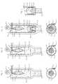
- the device essentially consists from a combustion chamber 1 in which the burner 3 generated by a Burner flame 4 burns out.
- the flue gas 5 is discharged through the discharge 14th derived.
- the feedstock 6 is distributed over the circumference of the Combustion chamber wall 2, also the burner side of the combustion chamber 1 fed.
- a vertical arrangement of the combustion chamber 1 and constructed "Fall Burner" 3 and continue corresponding distance between Burner flame 4 and feed 6 is a heating of the Feedstock 6 with simultaneous cooling of the flue gases 5 instead.
- the uniform distribution of the feedstock 6 over the circumference of Combustor wall 2 can be achieved, for example, that the Material entry 7 by tangential blowing of the feedstock 6 means a pneumatic conveying takes place.
- the occurring cyclone effect causes the feed 6 to concentrate on the combustion chamber wall 2 and the conveying air as an insulating layer between feed 6 and Burner flame 4 is used.
- the arrangement of the device not further bound to the vertical position.
- the combustion chamber 1 is additionally through an outer chamber. 9 envelops.
- the material entry 7 takes place in the annular gap 8 generated thereby.
- the combustion chamber 1 can, as shown in Fig. 2, as a pipe section be formed so that flue gas 5 and feed 6 only in the mix subsequent mixing chamber 12.
- the mixing is through intensified the delivery pressure of the feedstock 6.
- between combustion chamber 1 and annular gap 8 is no connection, so that there is no mixing of the feedstock 6 with the flue gas. 5 comes.
- This design also allows operation in the Countercurrent method, i. the flow direction of the feedstock 6 is the opposite of the flue gas 5.
- Fig. 3 shows a device in which the combustion chamber 1 additionally by a combustion chamber bottom 10 is completed.
- the combustion chamber floor 10 separates combustion chamber 1 and mixing chamber 12.
- the mixing chamber 12th Between combustion chamber 1 and mixing chamber 12 remain connections, through which the flue gas 5 can get into the mixing chamber 12, for Example, an annular gap 8 as in Fig.3.
- the starting material 6 is also in the Mixed chamber 12 passed, in Fig. 3, for example, by a deflection to about 180 °.
- the delivery pressure of the feedstock 6 takes place in the Mixing chamber 12 intensive mixing with the flue gas 5.
- From the Mixing chamber 12 passes the flue gas feed mixture over the Catching space 13 for discharge 14. But there are also solutions conceivable in where the flue gas is discharged without entering the mixing chamber 12 arrive and without mixing with the Einspezstoff 6.
- Fig. 4 shows a device which an even more intensive mixing of Feedstock 6 causes the flue gas 5, with simultaneous extraction the flue gases 5 from the combustion chamber 1.
- the annular gap 8 for the feed 6 in the area of merging with the flue gas 5 as Nozzle 11 is formed.
- the combustion chamber bottom 10 is adapted and forms with the outer chamber 9, the driving and mixing chamber 12 of a jet pump. This also known as Venturi principle method also applies to the Water jet pump application.
- the trap 13 can also by the Shaping the combustion chamber bottom 10 are formed by demselbigen.
Landscapes
- Engineering & Computer Science (AREA)
- Chemical & Material Sciences (AREA)
- Dispersion Chemistry (AREA)
- Mechanical Engineering (AREA)
- General Engineering & Computer Science (AREA)
- Drying Of Solid Materials (AREA)
- Crucibles And Fluidized-Bed Furnaces (AREA)
Description
- Fig. 1, Fig. 2
- sowie Fig. 3 jeweils eine Ausführungsform einer erfindungsgemäßen Vorrichtung, wobei im oberen Teil der jeweiligen Figur ein Querschnitt und im unteren Bereich eine Draufsicht der Vorrichtung dargestellt ist, und
- Fig. 4
- eine Teilansicht einer Vorrichtung im Querschnitt.
- 1
- Brennkammer
- 2
- Brennkammerwand
- 3
- Brenner
- 4
- Brennerflamme
- 5
- Rauchgas
- 6
- Einsatzstoff
- 7
- Materialeintrag
- 8
- Ringspalt
- 9
- Außenkammer
- 10
- Brennkammerboden
- 11
- Düse
- 12
- Mischkammer
- 13
- Fangamr
- 14
- Austrag
- 15
- Isolierung
Claims (13)
- Verfahren zur Erhitzung und Trocknung eines staubförmigen oder feinkörnigen Einsatzstoffes (6), dadurch gekennzeichnet, dass innerhalb einer von einer Brennkammerwand (2) begrenzten Brennkammer (1) eine Brennerflamme (4) erzeugt wird, über einen Materialeintrag (7) der Einsatzstoff (6) der Brennkammerwand (2) zugeleitet wird, der Einsatzstoff (6) entlang der Brennkammerwand (2) bewegt wird, wobei während der Bewegung des Einsatzstoffes (6) entlang der Brennkammerwand (2) der Einsatzstoff (6) mittels der Brennerflamme (4) erhitzt und getrocknet wird.
- Verfahren nach Anspruch 1, dadurch gekennzeichnet, dass der Einsatzstoff (6) pneumatisch gefördert wird.
- Verfahren nach Anspruch 1 oder 2, dadurch gekennzeichnet, dass der Einsatzstoff (6) tangential auf die Brennkammerwand (2) geleitet wird und/oder schraublinienförmig um die Brennerflamme (4) geführt wird.
- Verfahren nach einem oder mehreren der Ansprüche 1 bis 3, dadurch gekennzeichnet, dass der Einsatzstoff (6) in die Ausbrandzone der Brennerflamme (4) geleitet wird.
- Verfahren nach einem oder mehreren der Ansprüche 1 bis 4, dadurch gekennzeichnet, dass der Einsatzstoff (6) und das Rauchgas (5) der Brennerflamme (4), vorzugsweise in einer Mischkammer (12), vermischt werden.
- Verfahren nach einem oder mehreren der Ansprüche 1 bis 5, dadurch gekennzeichnet, dass das Rauchgas (3) und der Einsatzstoff (6) getrennt, vorzugsweise entlang der Brennkammerwand (2), geführt werden.
- Verfahren nach einem oder mehreren der Ansprüche 1 bis 6, dadurch gekennzeichnet, dass der Einsatzstoff (6) mittels eines zwischen der Brennkammerwand (2) und einer Außenkammer (9) ausgebildeten Ringspaltes (8) geführt wird.
- Verfahren nach einem oder mehreren der Ansprüche 1 bis 7, dadurch gekennzeichnet, dass das Rauchgas (5) mittels des Förderdrucks des Einsatzstoffes (6) angesaugt wird.
- Verfahren nach einem oder mehreren der Ansprüche 1 bis 8, dadurch gekennzeichnet, dass der Einsatzstoff (6) und/oder das Rauchgas (5) über einen Austrag (14), insbesondere mittels Unterdrucks, entfernt werden.
- Vorrichtung zur Durchführung des Verfahrens nach einem oder meh- . reren der Ansprüche 1 bis 9, dadurch gekennzeichnet, dass ein Brenner (3) zur Erzeugung einer Brennerflamme (4), eine Brennkammer (1) mit einer Brennkammerwand (2), ein Materialeintrag (7) zur Zuleitung des Einsatzstoffes (6) auf die Brennkammerwand (2) und ein Mittel zur Bewegung des Einsatzstoffes (6) entlang der Brennkammerwand (2) vorgesehen sind.
- Vorrichtung nach Anspruch 10, dadurch gekennzeichnet, dass ein pneumatisches Fördermittel für den Einsatzstoff (6) vorgesehen ist.
- Vorrichtung nach Anspruch 10 oder 11, dadurch gekennzeichnet, dass ein Mittel, insbesondere eine Außenkammer (9), zur Ausbildung eines Ringspaltes (8) vorgesehen ist.
- Vorrichtung nach einem der Ansprüche 10 bis 12, dadurch gekennzeichnet, dass eine Mischkammer (12) in der Brennkammer (1) und/oder ein, insbesondere mit Unterdruck beaufschlagbarer, Austrag (14) vorgesehen sind.
Applications Claiming Priority (2)
| Application Number | Priority Date | Filing Date | Title |
|---|---|---|---|
| DE19809067A DE19809067A1 (de) | 1998-03-04 | 1998-03-04 | Verfahren und Vorrichtung zur Trocknung und/oder Erhitzung staubförmiger bzw. feinkörniger Stoffe |
| DE19809067 | 1998-03-04 |
Publications (3)
| Publication Number | Publication Date |
|---|---|
| EP0949476A2 EP0949476A2 (de) | 1999-10-13 |
| EP0949476A3 EP0949476A3 (de) | 1999-12-29 |
| EP0949476B1 true EP0949476B1 (de) | 2005-02-09 |
Family
ID=7859577
Family Applications (1)
| Application Number | Title | Priority Date | Filing Date |
|---|---|---|---|
| EP99104276A Expired - Lifetime EP0949476B1 (de) | 1998-03-04 | 1999-03-03 | Verfahren und Vorrichtung zur Trocknung und Erhitzung staubförmiger bzw. feinkörniger Stoffe |
Country Status (4)
| Country | Link |
|---|---|
| EP (1) | EP0949476B1 (de) |
| AT (1) | ATE289049T1 (de) |
| DE (2) | DE19809067A1 (de) |
| ES (1) | ES2236978T3 (de) |
Families Citing this family (1)
| Publication number | Priority date | Publication date | Assignee | Title |
|---|---|---|---|---|
| CN119178167B (zh) * | 2024-10-10 | 2025-09-23 | 北京航空航天大学 | 一种应用于高高空低压环境的h2燃烧室头部结构 |
Family Cites Families (15)
| Publication number | Priority date | Publication date | Assignee | Title |
|---|---|---|---|---|
| US2973727A (en) * | 1957-02-22 | 1961-03-07 | Orr & Sembower Inc | Pulverised fuel burner |
| US3596890A (en) * | 1968-02-19 | 1971-08-03 | Alastair G M Small | Drying apparatus |
| GB1208033A (en) * | 1968-05-09 | 1970-10-07 | Stanley Horrocks | A method of and apparatus for mixing a high temperature gas stream containing products of combustion with a low temperature gas or air stream containing solid particles |
| GB1453834A (en) * | 1973-02-23 | 1976-10-27 | Barr Murphy Ltd | Method of and apparatus for drying particulate materials s |
| GB1570276A (en) * | 1976-12-31 | 1980-06-25 | White J | Method and apparatus for heating particulate solids |
| DE2808874C2 (de) * | 1978-03-02 | 1985-01-24 | Smit Ovens Nijmegen B.V., Nijmegen | Vorrichtung zur Verbrennung von in einem Gasstrom mitgeführten brennbaren Stoffen bzw. zur Erwärmung von Luft |
| US4190415A (en) * | 1978-07-10 | 1980-02-26 | Singrey Raymond E | Chip drying and cleaning device |
| FR2438679A1 (fr) * | 1978-10-11 | 1980-05-09 | Nal Etu Exper Machinisme Centr | Procede et appareil de traitement thermique de matieres combustibles |
| FR2543280B1 (fr) * | 1983-03-23 | 1987-12-04 | Gaz De France | Procede et installation de traitement par voie thermique de produits divises |
| US5014631A (en) * | 1988-06-09 | 1991-05-14 | Jgc Corporation | Cyclone furnace |
| DE3915740A1 (de) * | 1989-05-13 | 1990-11-15 | Ludger Schumacher | Einrichtung zur durchfuehrung von hochtemperaturprozessen |
| US5007181A (en) * | 1990-01-22 | 1991-04-16 | Gte Products Corporation | Deagglomerating direct-fired flash dryer for drying stir-in phosphors and method of using same |
| DE4115348C2 (de) * | 1991-05-10 | 2000-08-10 | Deutz Ag | Verfahren zur Hochtemperaturbehandlung von feinkörnigen Feststoffen in einem Schmelzzyklon |
| DE4123306C2 (de) * | 1991-07-13 | 2000-05-25 | Deutz Ag | Anlage zur thermischen Behandlung von mehlförmigen Rohmaterialien |
| DK138991A (da) * | 1991-07-24 | 1993-01-25 | Cimbria Unigrain Ltd | Apparat til toerring af slam og lignende |
-
1998
- 1998-03-04 DE DE19809067A patent/DE19809067A1/de not_active Ceased
-
1999
- 1999-03-03 AT AT99104276T patent/ATE289049T1/de active
- 1999-03-03 ES ES99104276T patent/ES2236978T3/es not_active Expired - Lifetime
- 1999-03-03 DE DE59911572T patent/DE59911572D1/de not_active Expired - Lifetime
- 1999-03-03 EP EP99104276A patent/EP0949476B1/de not_active Expired - Lifetime
Also Published As
| Publication number | Publication date |
|---|---|
| ATE289049T1 (de) | 2005-02-15 |
| EP0949476A3 (de) | 1999-12-29 |
| DE19809067A1 (de) | 1999-09-09 |
| EP0949476A2 (de) | 1999-10-13 |
| ES2236978T3 (es) | 2005-07-16 |
| DE59911572D1 (de) | 2005-03-17 |
Similar Documents
| Publication | Publication Date | Title |
|---|---|---|
| DE69618613T2 (de) | Verfahren und vorrichtung zum trocknen und heizen | |
| DE69730702T3 (de) | Vorrichtung und verfahren zur verbrennung von brennstoff | |
| DE19536837B4 (de) | Vorrichtung und Verfahren zum Einspritzen von Brennstoffen in komprimierte gasförmige Medien | |
| DE3151164C2 (de) | Vorrichtung zum Blähen von Perlit, Vermiculit und ähnlichem Blähgut | |
| DE10260733B4 (de) | Verfahren und Anlage zur Wärmebehandlung von eisenoxidhaltigen Feststoffen | |
| DE10260739B3 (de) | Verfahren und Anlage zur Herstellung von Metalloxid aus Metallverbindungen | |
| DE10260731B4 (de) | Verfahren und Anlage zur Wärmebehandlung von eisenoxidhaltigen Feststoffen | |
| AT411363B (de) | Einrichtung zum schmelzen von stäuben | |
| DE60124116T2 (de) | Verfahren und anlage zur herstellung von zementklinker | |
| DE2510765C2 (de) | Verfahren zur Wärmebehandlung feinkörnigen oder flüssigen Materials und Ofen zum Durchführen des Verfahrens | |
| EP0949476B1 (de) | Verfahren und Vorrichtung zur Trocknung und Erhitzung staubförmiger bzw. feinkörniger Stoffe | |
| DE2406464A1 (de) | Verfahren und vorrichtung zum trocknen teilchenfoermiger materialien | |
| DE2624970B2 (de) | Schachtofen zur Kalzinierung und Röstung von pulverförmigem Gut in der Wirbelschicht | |
| DE10156616B4 (de) | Verfahren zur Mitverbrennung von mechanisch entwässertem Klärschlamm in einem Wirbelschichtkessel mit stationärer oder schwach expandierter Wirbelschicht | |
| DE1501801A1 (de) | Verfahren und Vorrichtung zum Verbrennen von zerstaeubbaren Brennstoffen | |
| DE2449798A1 (de) | Wirbelschichtofen fuer die verbrennung von teilweise entwaessertem schlamm | |
| DE891314C (de) | Verfahren zum Verfeuern von Kohlenstaub in zwei Teilstroemen verschiedener Korngroesse und Anwendung des Verfahrens auf Kohlenstaubfeuerungen mit mehr als zwei Teilstroemen | |
| DD248109A1 (de) | Vorrichtung zur thermischen behandlung von feinkoernigen stoffen | |
| EP3244989B1 (de) | Verfahren zur reduzierung von stickoxiden im abgas einer flugstrombehandlungsanlage | |
| EP4437273B1 (de) | Verfahren und vorrichtung zur behandlung und neutralisierung von umweltschädlichen und/oder toxischen abgasen | |
| EP2984408B1 (de) | Brenneinrichtung | |
| DE10029724C2 (de) | Verfahren zum Blähen von Vermiculit | |
| DE1157333B (de) | Verbrennungsvorrichtung fuer fluessige Brennstoffe | |
| DE2843883C2 (de) | Verfahren zur Erzeugung von schwefelarmem Koksstaub und Gas durch Ent- und Teilvergasung von Kohlenstaub in einer Reaktionskammer | |
| DE2843883C3 (de) | Verfahren zur Erzeugung von schwefelarmem Koksstaub und Gas durch Ent- und Teilvergasung von Kohlenstaub in einer Reaktionskammer |
Legal Events
| Date | Code | Title | Description |
|---|---|---|---|
| PUAI | Public reference made under article 153(3) epc to a published international application that has entered the european phase |
Free format text: ORIGINAL CODE: 0009012 |
|
| AK | Designated contracting states |
Kind code of ref document: A2 Designated state(s): AT CH DE ES FR GB IT LI NL SE |
|
| AX | Request for extension of the european patent |
Free format text: AL;LT;LV;MK;RO;SI |
|
| PUAL | Search report despatched |
Free format text: ORIGINAL CODE: 0009013 |
|
| AK | Designated contracting states |
Kind code of ref document: A3 Designated state(s): AT BE CH CY DE DK ES FI FR GB GR IE IT LI LU MC NL PT SE |
|
| AX | Request for extension of the european patent |
Free format text: AL;LT;LV;MK;RO;SI |
|
| RIC1 | Information provided on ipc code assigned before grant |
Free format text: 6F 26B 3/18 A, 6F 26B 17/10 B, 6F 28C 3/12 B, 6F 26B 23/02 B |
|
| 17P | Request for examination filed |
Effective date: 20000614 |
|
| AKX | Designation fees paid |
Free format text: AT CH DE ES FR GB IT LI NL SE |
|
| 17Q | First examination report despatched |
Effective date: 20020423 |
|
| GRAP | Despatch of communication of intention to grant a patent |
Free format text: ORIGINAL CODE: EPIDOSNIGR1 |
|
| RTI1 | Title (correction) |
Free format text: METHOD AND DEVICE FOR DRYING AND HEATING GRANULATED RESPECTIVELY POWDERY MATERIALS |
|
| GRAS | Grant fee paid |
Free format text: ORIGINAL CODE: EPIDOSNIGR3 |
|
| GRAA | (expected) grant |
Free format text: ORIGINAL CODE: 0009210 |
|
| RAP1 | Party data changed (applicant data changed or rights of an application transferred) |
Owner name: LINTEC GMBH & CO. KG |
|
| RIN1 | Information on inventor provided before grant (corrected) |
Inventor name: NISSEN, JENS PETER |
|
| AK | Designated contracting states |
Kind code of ref document: B1 Designated state(s): AT CH DE ES FR GB IT LI NL SE |
|
| REG | Reference to a national code |
Ref country code: GB Ref legal event code: FG4D Free format text: NOT ENGLISH |
|
| REG | Reference to a national code |
Ref country code: CH Ref legal event code: NV Representative=s name: KIRKER & CIE SA Ref country code: CH Ref legal event code: EP |
|
| GBT | Gb: translation of ep patent filed (gb section 77(6)(a)/1977) |
Effective date: 20050209 |
|
| REF | Corresponds to: |
Ref document number: 59911572 Country of ref document: DE Date of ref document: 20050317 Kind code of ref document: P |
|
| REG | Reference to a national code |
Ref country code: SE Ref legal event code: TRGR |
|
| REG | Reference to a national code |
Ref country code: ES Ref legal event code: FG2A Ref document number: 2236978 Country of ref document: ES Kind code of ref document: T3 |
|
| PLBE | No opposition filed within time limit |
Free format text: ORIGINAL CODE: 0009261 |
|
| STAA | Information on the status of an ep patent application or granted ep patent |
Free format text: STATUS: NO OPPOSITION FILED WITHIN TIME LIMIT |
|
| ET | Fr: translation filed | ||
| 26N | No opposition filed |
Effective date: 20051110 |
|
| PGFP | Annual fee paid to national office [announced via postgrant information from national office to epo] |
Ref country code: FR Payment date: 20120403 Year of fee payment: 14 Ref country code: CH Payment date: 20120323 Year of fee payment: 14 |
|
| PGFP | Annual fee paid to national office [announced via postgrant information from national office to epo] |
Ref country code: GB Payment date: 20120322 Year of fee payment: 14 Ref country code: IT Payment date: 20120327 Year of fee payment: 14 Ref country code: SE Payment date: 20120322 Year of fee payment: 14 |
|
| PGFP | Annual fee paid to national office [announced via postgrant information from national office to epo] |
Ref country code: NL Payment date: 20120327 Year of fee payment: 14 Ref country code: DE Payment date: 20120403 Year of fee payment: 14 |
|
| PGFP | Annual fee paid to national office [announced via postgrant information from national office to epo] |
Ref country code: AT Payment date: 20120321 Year of fee payment: 14 |
|
| PGFP | Annual fee paid to national office [announced via postgrant information from national office to epo] |
Ref country code: ES Payment date: 20120326 Year of fee payment: 14 |
|
| REG | Reference to a national code |
Ref country code: NL Ref legal event code: V1 Effective date: 20131001 |
|
| REG | Reference to a national code |
Ref country code: SE Ref legal event code: EUG |
|
| PG25 | Lapsed in a contracting state [announced via postgrant information from national office to epo] |
Ref country code: SE Free format text: LAPSE BECAUSE OF NON-PAYMENT OF DUE FEES Effective date: 20130304 |
|
| REG | Reference to a national code |
Ref country code: CH Ref legal event code: PL |
|
| REG | Reference to a national code |
Ref country code: AT Ref legal event code: MM01 Ref document number: 289049 Country of ref document: AT Kind code of ref document: T Effective date: 20130303 |
|
| GBPC | Gb: european patent ceased through non-payment of renewal fee |
Effective date: 20130303 |
|
| REG | Reference to a national code |
Ref country code: FR Ref legal event code: ST Effective date: 20131129 |
|
| PG25 | Lapsed in a contracting state [announced via postgrant information from national office to epo] |
Ref country code: GB Free format text: LAPSE BECAUSE OF NON-PAYMENT OF DUE FEES Effective date: 20130303 Ref country code: DE Free format text: LAPSE BECAUSE OF NON-PAYMENT OF DUE FEES Effective date: 20131001 Ref country code: FR Free format text: LAPSE BECAUSE OF NON-PAYMENT OF DUE FEES Effective date: 20130402 Ref country code: LI Free format text: LAPSE BECAUSE OF NON-PAYMENT OF DUE FEES Effective date: 20130331 Ref country code: CH Free format text: LAPSE BECAUSE OF NON-PAYMENT OF DUE FEES Effective date: 20130331 Ref country code: AT Free format text: LAPSE BECAUSE OF NON-PAYMENT OF DUE FEES Effective date: 20130303 |
|
| REG | Reference to a national code |
Ref country code: DE Ref legal event code: R119 Ref document number: 59911572 Country of ref document: DE Effective date: 20131001 |
|
| PG25 | Lapsed in a contracting state [announced via postgrant information from national office to epo] |
Ref country code: NL Free format text: LAPSE BECAUSE OF NON-PAYMENT OF DUE FEES Effective date: 20131001 Ref country code: IT Free format text: LAPSE BECAUSE OF NON-PAYMENT OF DUE FEES Effective date: 20130303 |
|
| REG | Reference to a national code |
Ref country code: ES Ref legal event code: FD2A Effective date: 20150710 |
|
| PG25 | Lapsed in a contracting state [announced via postgrant information from national office to epo] |
Ref country code: ES Free format text: LAPSE BECAUSE OF NON-PAYMENT OF DUE FEES Effective date: 20130304 |