EP0949112B1 - Modular anchoring system in an automotive vehicle passenger compartment - Google Patents
Modular anchoring system in an automotive vehicle passenger compartment Download PDFInfo
- Publication number
- EP0949112B1 EP0949112B1 EP19990400817 EP99400817A EP0949112B1 EP 0949112 B1 EP0949112 B1 EP 0949112B1 EP 19990400817 EP19990400817 EP 19990400817 EP 99400817 A EP99400817 A EP 99400817A EP 0949112 B1 EP0949112 B1 EP 0949112B1
- Authority
- EP
- European Patent Office
- Prior art keywords
- slider
- slide rail
- slide
- longitudinal
- base
- Prior art date
- Legal status (The legal status is an assumption and is not a legal conclusion. Google has not performed a legal analysis and makes no representation as to the accuracy of the status listed.)
- Expired - Lifetime
Links
Images


Classifications
-
- B—PERFORMING OPERATIONS; TRANSPORTING
- B60—VEHICLES IN GENERAL
- B60N—SEATS SPECIALLY ADAPTED FOR VEHICLES; VEHICLE PASSENGER ACCOMMODATION NOT OTHERWISE PROVIDED FOR
- B60N2/00—Seats specially adapted for vehicles; Arrangement or mounting of seats in vehicles
- B60N2/02—Seats specially adapted for vehicles; Arrangement or mounting of seats in vehicles the seat or part thereof being movable, e.g. adjustable
- B60N2/04—Seats specially adapted for vehicles; Arrangement or mounting of seats in vehicles the seat or part thereof being movable, e.g. adjustable the whole seat being movable
- B60N2/06—Seats specially adapted for vehicles; Arrangement or mounting of seats in vehicles the seat or part thereof being movable, e.g. adjustable the whole seat being movable slidable
- B60N2/08—Seats specially adapted for vehicles; Arrangement or mounting of seats in vehicles the seat or part thereof being movable, e.g. adjustable the whole seat being movable slidable characterised by the locking device
- B60N2/0812—Location of the latch
- B60N2/0818—Location of the latch inside the rail
-
- B—PERFORMING OPERATIONS; TRANSPORTING
- B60—VEHICLES IN GENERAL
- B60N—SEATS SPECIALLY ADAPTED FOR VEHICLES; VEHICLE PASSENGER ACCOMMODATION NOT OTHERWISE PROVIDED FOR
- B60N2/00—Seats specially adapted for vehicles; Arrangement or mounting of seats in vehicles
- B60N2/005—Arrangement or mounting of seats in vehicles, e.g. dismountable auxiliary seats
- B60N2/015—Attaching seats directly to vehicle chassis
- B60N2/01508—Attaching seats directly to vehicle chassis using quick release attachments
- B60N2/01516—Attaching seats directly to vehicle chassis using quick release attachments with locking mechanisms
- B60N2/01525—Attaching seats directly to vehicle chassis using quick release attachments with locking mechanisms with locking elements expanding inside or under the vehicle floor or rail
- B60N2/01541—Attaching seats directly to vehicle chassis using quick release attachments with locking mechanisms with locking elements expanding inside or under the vehicle floor or rail using moving hooks
-
- B—PERFORMING OPERATIONS; TRANSPORTING
- B60—VEHICLES IN GENERAL
- B60N—SEATS SPECIALLY ADAPTED FOR VEHICLES; VEHICLE PASSENGER ACCOMMODATION NOT OTHERWISE PROVIDED FOR
- B60N2/00—Seats specially adapted for vehicles; Arrangement or mounting of seats in vehicles
- B60N2/02—Seats specially adapted for vehicles; Arrangement or mounting of seats in vehicles the seat or part thereof being movable, e.g. adjustable
- B60N2/04—Seats specially adapted for vehicles; Arrangement or mounting of seats in vehicles the seat or part thereof being movable, e.g. adjustable the whole seat being movable
- B60N2/06—Seats specially adapted for vehicles; Arrangement or mounting of seats in vehicles the seat or part thereof being movable, e.g. adjustable the whole seat being movable slidable
- B60N2/07—Slide construction
- B60N2/0702—Slide construction characterised by its cross-section
- B60N2/072—Complex cross-section, e.g. obtained by extrusion
-
- B—PERFORMING OPERATIONS; TRANSPORTING
- B60—VEHICLES IN GENERAL
- B60N—SEATS SPECIALLY ADAPTED FOR VEHICLES; VEHICLE PASSENGER ACCOMMODATION NOT OTHERWISE PROVIDED FOR
- B60N2/00—Seats specially adapted for vehicles; Arrangement or mounting of seats in vehicles
- B60N2/02—Seats specially adapted for vehicles; Arrangement or mounting of seats in vehicles the seat or part thereof being movable, e.g. adjustable
- B60N2/04—Seats specially adapted for vehicles; Arrangement or mounting of seats in vehicles the seat or part thereof being movable, e.g. adjustable the whole seat being movable
- B60N2/06—Seats specially adapted for vehicles; Arrangement or mounting of seats in vehicles the seat or part thereof being movable, e.g. adjustable the whole seat being movable slidable
- B60N2/08—Seats specially adapted for vehicles; Arrangement or mounting of seats in vehicles the seat or part thereof being movable, e.g. adjustable the whole seat being movable slidable characterised by the locking device
- B60N2/0831—Movement of the latch
- B60N2/0837—Movement of the latch pivoting
- B60N2/0843—Movement of the latch pivoting about a longitudinal axis
Definitions
- the invention provides a system for adjusting the longitudinal position, and locking in the adjusted position of a sub-assembly on the horizontal floor of the passenger compartment of a motor vehicle.
- each end of the sub-base has two bolts of substantially longitudinal orientation, articulated around a pivot of longitudinal axis movable vertically, to selectively move upper extremities and lower bolts so that they selectively cooperate with respectively upper and lower zones of the associated slide, so as to ensure functions of longitudinal guiding, locking or unlocking by jamming, and vertical locking or extraction by jamming or loosening.
- the pivot of articulation of the bolts is animated by a movement of vertical translation which it transforms into a movement of rotation of the bolts along the axis of the slide.
- This movement of vertical translation is obtained by vertical displacement of the pivot, consisting of a ball forming a nut, along the thread a screw linked to a frame of said device, and whose screwing or unscrewing selectively causes the spacing or approximation of the bolts, and, consequently immobilization of the base relative to the slide.
- the sub-assemblies being likely to constitute loads having large vertical dimensions, their fastening system must be designed to withstand non-uniform tearing of the anchor points. If, for any reason, a subset with more of an anchor point sees one of its anchor points torn off, it occurs the appearance of a couple on the other points anchor and the whole load fixing is weakened. In the event of an impact, the load forming the lever arm, the longitudinal accelerations of the load are likely to exert a shearing force on the anchor points of sub-assemblies, which may cause rupture of the anchor points of the sub-assemblies in case the means of locking the anchor points are insufficient.
- this system does not provide a fixing system of any subset by means of rings and straps.
- this solution is not acceptable in the case of a non-utility vehicle, and in particular a vehicle versatile such as a people carrier, in which the passenger compartment is led to receive seats, and therefore cannot include protruding rings permanently installed to meet aesthetic and safety imperatives, passengers who may be injured by the rings.
- the invention proposes a new conception of a previously mentioned type adjustment system which overcomes the aforementioned drawbacks.
- the invention proposes a system of the type previously described, characterized in that the sub-assembly has a ring and that the first slide is ordered in its vertical displacement by manual actions vertical on the lashing ring which is integral with the first slide, and in that the second slide is controlled in its vertical movements by manual actions vertical on a gripping ring secured to the second slide.
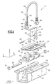
- the system 10 comprises a base 12 produced in the form of a horizontal plate which extends parallel to a floor (not shown) of the vehicle, and which can optionally be associated with an element interior design of the vehicle such as a seat, shelf or any interior design element (not shown).
- the base 12 is intended to be received, as seen also in FIG. 2, in a slide 16 which is fixed to the vehicle floor.
- the slide 16 is made from a profile, for example a drawn bar or Pressed.
- the base 12 has two horizontal wings 24, symmetrical with respect to the median longitudinal plane P of the slide 16, which extend transversely over the entire length of the base 12, and which have on their faces lower 26 of the pads 28, made of low material coefficient of friction, intended, as can also be seen in the Figure 2, to allow the support of the base 12 on two wings upper 30 of the slide 16, which extend horizontally and transversely outwards, and in part inwards, from the end edges upper side faces 32 of the slide 16.
- the pads of low material coefficient of friction 28 are carried by the base 12, which reduces their length to the longitudinal dimension of the base 12, thereby significantly lowering the manufacturing costs, as opposed to a design where the pads 28 would extend longitudinally over the entire length upper wings 30 of the slide 16.
- a central part longitudinal 18 of base 12 is pierced with oblong holes 20, vertical direction, and which extend transversely from side and on the other side of the median plane P of the device 10, to receive in vertical sliding a first slide 36.
- the slide 36 has, in an upper part, a ring lashing 22, inverted U-shaped fitting in the plane median P, and which is advantageously produced from a curved bar in an appropriate shape.
- the slide In a part lower extending the branches of the U of the ring 22, the slide has two coaxial bores 34 and longitudinal.
- the bores 34 are carried by shapes in hook 38 made of material with the arched bar of the ring lashing 22.
- the slide 36 can then advantageously be made in one piece, for example by deformation plastic of a steel wire.
- the slide 36 is guided in its movements vertical by contact of intermediate cylindrical spans 40, visible in FIG. 3, and forming part of the ring lashing 22, with the inner faces of the oblong holes 20 from the base 12.
- intermediate cylindrical bearings 40 have flanges at their upper ends annulars 42, illustrated by FIGS. 1 and 3.
- the flanges annulars 42 are for example split washers removable, mounted in annular grooves (not shown) located at the upper ends of the staves intermediate cylindrical 40.
- the slide 36 can therefore move in the vertical direction relative to the base 12, while being limited in its downward vertical displacements by the compression of the springs 44. Indeed, when the springs 44 are sufficiently compressed, their turns are contiguous and the slide 36 can no longer descend. By default, the slide 36 is resiliently drawn upwards by the springs 44.
- the slide 36 In its longitudinal bores 34, the slide 36 is likely to receive a longitudinal axis 50 on which are threaded, as can be seen in Figure 3, five organs lock 52 received longitudinally between the branches of the U of the slide 36, and being able to pivot freely around of said axis 50, for example by occupying an angular position locked assembly, visible in figure 2.
- the alignment of the locking devices in association with the means of control forms two combs 53, shown in Figures 1 and 3, comprising two and three members 52 respectively.
- the combs 53 can each be made in one piece by molding, forging, and / or machining.
- the slide 16 has in one direction longitudinal of the teeth 17 which extend transversely to the interior on interior faces 21 of its upper wings 30, forming along the length of the slide 16 a rack 19.
- rack 19 is intended to receive between teeth 17 upper active parts 94 organs locking 52 of the combs 53.
- the base 12 comprises two transverse slots 58, arranged between the oblong holes 20, which are capable of guiding in vertical sliding a second slide 56.
- the second slide 56 is formed by a curved U-shaped plate, an upper part of which forms a grip ring 68, and of which a lower part has two legs vertical transverse 55, which are drilled longitudinally through holes 60 of a longitudinal rod 62, intended for cross curvilinear lights 64 of the aforementioned organs 52.
- the transverse legs 55 of the second slide 56 have a transverse size equal to the width of the base slots 58
- the second slide 36 is made of cut and folded sheet metal, which reduces considerably the manufacturing costs.
- the transverse legs 55 are pierced with holes oblongs 66, which open vertically at the ends lower 54 of the legs 55 of the second slide 56, and whose diameter corresponds to that of the longitudinal axis 50 which receives the locking members 52 of the combs 53, so that the second slide 56 is guided vertically by a part by the slots 58, and secondly by the axis 50 on which the legs 55 are guided in sliding through oblong holes 66.
- the transverse connection of the second slide 56 to first slide 36 via the oblong holes 66, of the longitudinal axis 50, and of the bores 34 guarantees good transverse centering of the first slide 36 in the holes transverse oblongs 20.
- the second slide 56 is resiliently biased towards the bottom relative to the base 12 by means of a spring flat 67 supported on the one hand under a transverse leg horizontal 70 of the base 12 which is arranged longitudinally between the slots 58, and on the other hand in side slots 72 arranged longitudinally in the branches of the U of the second slide 56.
- the return spring 44 of the first slide 36 does not can recall the first slide 36 only upwards and does not form a stop for its vertical movements upwards.
- the return spring 67 has a calibration different from the springs 44 of the first slide 36. In position rest, the return spring 67 is prestressed so that it tends to recall the second slide 56 down but in is prevented by the support of the legs 54 on the longitudinal axis 50 of the first slide 36, which is recalled upwards by the springs 44, of greater stiffness than that of spring 67.
- the transverse retaining tab 70 of the flat spring 67 is obtained by punching the plate forming the base 12, with which it came integrally.
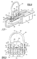
- Figure 2 shows the system 10 in position locking assembly.
- the locking members 52 of the combs 53 are carried by the longitudinal axis 50 which is immobilized in its transverse displacements by coaxial bores longitudinal 34 of the hooks 38 of the first slide 36, and is immobilized longitudinally by fixing means 51 such as elastic rings or, alternatively (not shown), a screw / nut system.
- the locking members 52 of the combs 53 are by elsewhere crossed by the longitudinal rod 62 which occupies a determined position in the slots 64 of the organs 52, of so that the upper parts of the locking members 52 of the combs 53 extend transversely outwards in the slide 16 between the teeth 17 of the rack 19.
- the locking members 52 are arranged alternately on the longitudinal axis 50, so that two organs 52 consecutive cooperate with two opposing spaces included between two teeth 17 of the rack 19.
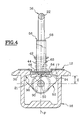
- Figure 4 shows the system 10 in position locked.
- the locking members 52 of the combs 53 have in the transverse plane P 'a profile in the form of a drop of water and are strung on axis 50 in the vicinity of their lower parts of larger dimensions 90. Their active upper parts 94 are received between the teeth 17 of the rack 19.
- the teeth 17 of the rack 19 views in the transverse plane P ' have a profile which is substantially triangular so as to favor the rapid extraction of locking members 52 of the combs 53 when these will, as will be described later, lead to retract.
- the teeth 17 of the rack 19 may have a profile in the form of parallelogram allowing better resistance to longitudinal efforts of the base 12.
- the slide 36 is therefore in the high position and the slide 56 is recalled in its low stop position on the axis 50 by the flat spring 67 shown in Figure 1, so that the longitudinal rod 62 is received in abutment at the end 96 of the lights 64 of the organs 52, which end 96 is opposite to the parts active 94 of said organs 52.
- the lights 64 are substantially in an arc and are not centered on axis 50.
- the distance E between the longitudinal rod 62 and the longitudinal axis 50 is minimal and the support of the rod longitudinal 62 in abutment at the bottom of the end 96 of the lights 64 keeps organs 52 in one position maximum transverse dimensions.
- Figure 5 illustrates the system configuration 10 when a user pushes the lashing ring 22 towards the bottom, as shown by the white arrow.
- the first slide 36 then occupies a position of low stop in which the active parts 94 of the organs locking 52 of the combs 53 are no longer received between teeth 17, but exposed below.
- the second slide descends with the first slide 36, since the spring 67 tends to return it towards the bottom and that the axis 50, forming a stop for the second slide solidly descends from the first slide 36.
- the locking members 52 of the combs 53 have maximum transverse dimensions, while being released from the teeth 17 of the rack 19.
- This position corresponds to a longitudinal adjustment position, by example, when a user wants to adjust the position longitudinal of the lashing ring 22, or of a possible vehicle interior sub-assembly which would be linked to the base 12.
- the weight of the base 12 and the sub all of the vehicle's interior fittings possibly linked plate the base 12 against the wings upper 30 of the slide 16 via the pads 28 and wings 24, and consequently the lashing ring 22 does not can move only longitudinally.
- the maximum transverse size of the locking members 52 of the combs 53 guarantees advantageously that it does not leave the slide 16 in the event that an effort is exerted vertically towards the high on the lashing ring 22, as would be the case if a load, secured to the ring 22 tipped during a violent shock.
- Figure 6 shows the system 10 in position vertical engagement or disengagement of the base 12.
- the longitudinal rod 62 has slipped inside lights 64 made in the locking members 52 of the combs 53 to reach a stop position 97, which is the opposite of the previous position 96 in the lights 64.
- the sliding bearing of the longitudinal rod 62 in the lights 64 of the organs 52 during the ascent of the slide 56 causes the inward transverse retraction of the organs 52, and the base 12 is no longer while resting on the wings 30 of the slide 16.
- the base 12 can then be removed of the slide 16.
- the ascent of the second slide 56 is perfectly ensured by the slots 58 of the base 12 and by the oblong holes 66 of the lower ends 54 of the second slide 56 which receive the longitudinal axis 50 integral with the first slide 36.
- this position corresponds to a use in engagement or release of the system 10 in the slide 16 linked to the vehicle.
- This position allows by example of removing or adding a subset such as previously described with reference to FIG. 1, so that ability to use the passenger compartment of the vehicle concerned with a great modularity.
- FIG. 7 also illustrates an embodiment as a variant of the slide 16.
- the rack 19 of the slide 16 is produced by two plates 98, hollowed out at intervals regular, and arranged in the longitudinal direction of the slide 16 and inclined at an angle similar to that of the teeth 17 described with reference to the preceding figures, for cooperate with hook ends 100 located at ends of the active parts 94 of the organs 52.
- the teeth 17 of the rack are made up by the areas of material between two recesses of the plates 98.
Landscapes
- Engineering & Computer Science (AREA)
- Aviation & Aerospace Engineering (AREA)
- Transportation (AREA)
- Mechanical Engineering (AREA)
- Passenger Equipment (AREA)
- Seats For Vehicles (AREA)
- Body Structure For Vehicles (AREA)
- Lock And Its Accessories (AREA)
- Surgical Instruments (AREA)
Description
L'invention propose un système pour le réglage de la position longitudinale, et le blocage en position réglée d'un sous ensemble sur le plancher horizontal de l'habitacle d'un véhicule automobile.The invention provides a system for adjusting the longitudinal position, and locking in the adjusted position of a sub-assembly on the horizontal floor of the passenger compartment of a motor vehicle.
Selon une conception connue et conventionnelle, il a déjà été proposé d'aménager des séries de points d'ancrage de sous ensembles, sur le plancher du véhicule, chacun occupant une position déterminée de fixation.According to a known and conventional conception, it has already proposed to arrange series of anchor points of sub-assemblies, on the vehicle floor, each occupying a determined fixing position.
Toutefois, cette conception offre un nombre limité de possibilités de fixation. Un utilisateur désirant, dans une telle configuration, positionner un sous-ensemble dans l'habitacle d'un véhicule équipé de points d'ancrage fixes, ne peut utiliser que les emplacements prévus à cet effet, ce qui est pénalisant en matière de modularité d'aménagement de l'habitacle.However, this design offers a limited number of fixing possibilities. A user wishing, in such a configuration, positioning a sub-assembly in the passenger compartment a vehicle fitted with fixed anchor points, cannot use than the spaces provided for this purpose, which is penalizing in terms of modular interior design.
Pour résoudre ce problème, et notamment dans le cas ou les sous-ensembles sont des sièges, on a imaginé de permettre des latitudes de réglage des points d'ancrage des sous ensembles.To solve this problem, especially in the case where the sub-assemblies are seats, we imagined allow adjustment latitudes for anchor points subsets.
Dans ce domaine, l'invention se rapporte donc plus particulièrement à un système pour le réglage de la position longitudinale, et le blocage en position réglée d'un sous-ensemble, sur une structure d'un habitacle d'un véhicule automobile équipé d'au moins une glissière qui reçoit en coulissement longitudinal au moins un dispositif de guidage des déplacements longitudinaux et de verrouillage longitudinal et vertical en position réglée d'un socle du sous-ensemble, dont l'extrémité reçue dans la glissière est équipée d'un mécanisme expansible mobile commandé entre
- une première position extrême, dite d'engagement ou de dégagement vertical, dans laquelle deux organes de verrouillage du mécanisme expansible, à action symétrique et opposée par rapport à un plan médian vertical de la glissière, sont dans une position escamotée vers l'intérieur dans laquelle leur encombrement transversal permet l'introduction ou l'extraction verticale du mécanisme à travers une fente longitudinale médiane de la glissière délimitée par deux bords supérieurs longitudinaux (définis ailes dans la suite) et parallèles de la glissière ; et
- une seconde position extrême, dite de verrouillage, dans laquelle les deux organes s'étendent chacun transversalement en regard de deux faces intérieures des ailes supérieures de la glissière avec lesquelles ils coopèrent par accrochage, pour immobiliser le socle par rapport à la glissière longitudinalement et verticalement ;
- en passant par au moins une position intermédiaire, dite de réglage, dans laquelle les deux organes s'étendent chacun transversalement en regard des deux faces intérieures des ailes supérieures de la glissière, pour retenir verticalement le socle par rapport à la glissière et permettre des déplacements longitudinaux du socle à l'intérieur de la glissière,
- a first extreme position, called vertical engagement or disengagement, in which two locking members of the expandable mechanism, with symmetrical action and opposite with respect to a vertical median plane of the slide, are in a position retracted inwards in which their transverse dimensions allow the introduction or the vertical extraction of the mechanism through a median longitudinal slot of the slide delimited by two longitudinal upper edges (defined wings below) and parallel to the slide; and
- a second extreme position, called the locking position, in which the two members each extend transversely opposite two internal faces of the upper wings of the slide with which they cooperate by hooking, to immobilize the base relative to the slide longitudinally and vertically ;
- passing through at least one intermediate position, called an adjustment position, in which the two members each extend transversely opposite the two internal faces of the upper wings of the slide, in order to vertically retain the base relative to the slide and allow movement longitudinal of the base inside the slide,
Le document US-A-5.236.153 offre un exemple d'une telle réalisation.US-A-5,236,153 provides an example of a such an achievement.
Toutefois, il est limité à une application concernant exclusivement des sièges d'aéroplane, et cette conception fait appel à des moyens expansibles délicats à utiliser. En effet, chaque extrémité de socle de sous-ensemble comporte deux pênes d'orientation sensiblement longitudinale, articulés autour d'un pivot d'axe longitudinal mobile verticalement, pour déplacer sélectivement des extrémités supérieures et inférieures des pênes de sorte qu'elles coopèrent sélectivement avec des zones respectivement supérieures et inférieures de la glissière associée, de façon à assurer des fonctions de guidage, verrouillage ou déverrouillage longitudinal par coincement, et de verrouillage vertical ou extraction par coincement ou relâchement. Dans ce dispositif, le pivot d'articulation des pênes est animé d'un mouvement de translation verticale qu'il transforme en un mouvement de rotation des pênes suivant l'axe de la glissière. Ce mouvement de translation verticale est obtenu par déplacement vertical du pivot, constitué d'une bille formant écrou, le long du filetage d'une vis lié à un bâti du dit dispositif, et dont le vissage ou le dévissage provoque sélectivement l'écartement ou le rapprochement des pênes, et, par voie de conséquence l'immobilisation du socle par rapport à la glissière.However, it is limited to an application concerning exclusively airplane seats, and this design makes use of expandable means which are delicate to use. Indeed, each end of the sub-base has two bolts of substantially longitudinal orientation, articulated around a pivot of longitudinal axis movable vertically, to selectively move upper extremities and lower bolts so that they selectively cooperate with respectively upper and lower zones of the associated slide, so as to ensure functions of longitudinal guiding, locking or unlocking by jamming, and vertical locking or extraction by jamming or loosening. In this device, the pivot of articulation of the bolts is animated by a movement of vertical translation which it transforms into a movement of rotation of the bolts along the axis of the slide. This movement of vertical translation is obtained by vertical displacement of the pivot, consisting of a ball forming a nut, along the thread a screw linked to a frame of said device, and whose screwing or unscrewing selectively causes the spacing or approximation of the bolts, and, consequently immobilization of the base relative to the slide.
Dans le contexte d'un véhicule automobile pour lequel la modularité des sous ensembles va de pair avec la rapidité de manipulation, un tel système vis-écrou est inapproprié.In the context of a motor vehicle for which the modularity of the subsets goes hand in hand with the speed handling, such a screw-nut system is inappropriate.
De plus, si cette conception permet une grande modularité d'aménagement d'un habitacle d'aéroplane, elle ne peut en revanche être appliquée à un habitacle d'automobile pour lequel les impératifs d'immobilisation des sous-ensembles sont beaucoup plus draconiens. In addition, if this design allows a large modular layout of an airplane cabin, it does not can, however, be applied to an automobile interior for which the immobilization requirements of the sub-assemblies are much more draconian.
En effet, en cas de brutale décélération ou de choc, les sous ensembles doivent rester rigoureusement immobiles par rapport à leurs glissières, pour éviter qu'ils ne soient projetés dans l'habitacle. L'éventualité d'un choc interdit donc l'emploi de procédés de verrouillage longitudinal par coincement.In fact, in the event of a sudden deceleration or impact, the sub-assemblies must remain strictly stationary by compared to their slides, to prevent them from being thrown in the passenger compartment. The possibility of a shock therefore prohibits employment longitudinal locking methods by wedging.
Les sous-ensembles étant susceptibles de constituer des charges ayant des dimensions verticales importantes, leur système de fixation doit être conçu de façon à pouvoir résister à un arrachement non uniforme des points d'ancrage. Si, pour une raison quelconque, un sous ensemble comportant plus d'un point d'ancrage voit un de ses points d'ancrage arraché, il se produit l'apparition d'un couple sur les autres points d'ancrage et l'ensemble de la fixation de la charge est fragilisée. En cas de choc, le charge formant bras de levier, les accélérations longitudinales de la charge sont susceptibles d'exercer un effort de cisaillement sur les points d'ancrage des sous ensembles, qui risque de provoquer une rupture des points d'ancrage des sous-ensembles dans le cas où les moyens de verrouillage des points d'ancrages sont insuffisants.The sub-assemblies being likely to constitute loads having large vertical dimensions, their fastening system must be designed to withstand non-uniform tearing of the anchor points. If, for any reason, a subset with more of an anchor point sees one of its anchor points torn off, it occurs the appearance of a couple on the other points anchor and the whole load fixing is weakened. In the event of an impact, the load forming the lever arm, the longitudinal accelerations of the load are likely to exert a shearing force on the anchor points of sub-assemblies, which may cause rupture of the anchor points of the sub-assemblies in case the means of locking the anchor points are insufficient.
Il est donc préférable de décaler verticalement les fonctions de guidage et de verrouillage d'une telle fixation de façon à pouvoir opposer un couple résistant à un éventuel couple au niveau du socle qui résulterait de l'effort de cisaillement exercé sur le socle et provoquerait la rupture de la fixation du sous-ensemble.It is therefore preferable to vertically offset the guiding and locking functions of such a fixing so as to be able to oppose a resistant couple to a possible torque at the base which would result from the effort of shear exerted on the base and would cause the rupture of the fixing the sub-assembly.
Enfin, ce système ne prévoit pas de système de fixation d'un sous ensemble quelconque au moyen d'anneaux et de sangles.Finally, this system does not provide a fixing system of any subset by means of rings and straps.
De manière connue, il a déjà été proposé de disposer des anneaux à la surface du plancher d'un véhicule utilitaire. In known manner, it has already been proposed to have rings on the surface of the floor of a utility vehicle.
Un utilisateur désireux de disposer une charge dans un véhicule ainsi équipé à un endroit aux environs duquel il n'y a pas d'anneaux, est contraint d'utiliser des sangles de grande longueur afin de les accrocher à des anneaux éloignés, ce qui compromet la stabilité de la charge.A user wishing to have a charge in a vehicle so equipped in a location around which there is no no rings, is forced to use large straps length in order to hang them on distant rings, which compromises load stability.
De plus, cette solution n'est pas acceptable dans le cas d'un véhicule non utilitaire, et notamment un véhicule polyvalent tel qu'un monospace, dans lequel l'habitacle est amené à recevoir des sièges, et ne peut donc comporter d'anneaux protubérants installés à demeure, pour répondre à des impératifs d'esthétique et de sécurité, les passagers pouvant être amenés à se blesser avec les anneaux.In addition, this solution is not acceptable in the case of a non-utility vehicle, and in particular a vehicle versatile such as a people carrier, in which the passenger compartment is led to receive seats, and therefore cannot include protruding rings permanently installed to meet aesthetic and safety imperatives, passengers who may be injured by the rings.
Il importe donc de pouvoir bénéficier d'une conception d'anneaux de fixation amovibles, telle que celle décrite ci-dessus, qui permette de les déplacer et de les fixer en différents points de l'habitacle.It is therefore important to be able to benefit from a conception removable fixing rings, such as that described above, which allows them to be moved and fixed in different points in the passenger compartment.
L'invention propose une nouvelle conception d'un système de réglage du type mentionné précédemment qui permet de remédier aux inconvénients précités.The invention proposes a new conception of a previously mentioned type adjustment system which overcomes the aforementioned drawbacks.
Pour simplifier la commande du dit système et fournir une grande modularité de positions d'anneaux d'accrochage, l'invention propose un système du type précédemment décrit, caractérisé en ce que le sous-ensemble comporte un anneau d'arrimage, et en ce que le premier coulisseau est commandé dans ses déplacement verticaux par des actions manuelles verticales sur l'anneau d'arrimage qui est solidaire du premier coulisseau, et en ce que le second coulisseau est commandé dans ses déplacements verticaux par des actions manuelles verticales sur un anneau de préhension solidaire du second coulisseau.To simplify the order of said system and provide a large modularity of attachment ring positions, the invention proposes a system of the type previously described, characterized in that the sub-assembly has a ring and that the first slide is ordered in its vertical displacement by manual actions vertical on the lashing ring which is integral with the first slide, and in that the second slide is controlled in its vertical movements by manual actions vertical on a gripping ring secured to the second slide.
Selon d'autres caractéristiques de l'invention :
- le deuxième coulisseau est rappelé élastiquement vers une position basse par rapport au premier coulisseau ;
- le premier coulisseau comporte deux portées cylindriques intermédiaires de guidage, verticales, parallèles et symétriques par rapport à un plan vertical médian du socle, transversal à la glissière, qui sont guidées en coulissement dans des trous oblongs du socle de diamètre complémentaire, et en ce que le deuxième coulisseau comporte deux pattes de guidage verticales parallèles et symétriques par rapport au plan médian du premier coulisseau, et qui sont guidées en coulissement dans des fentes du socle de forme complémentaire ;
- les organes de verrouillage comportent des lumières curvilignes non centrées autour de leur axe d'articulation, qui déterminent une course verticale de la tige, portée par le deuxième coulisseau et reçue dans les lumières, de sorte que la course de la tige est égale à la course du deuxième coulisseau ;
- les organes des verrouillages sont des peignes dont des parties actives sont reçues entre des dents transversales de crémaillère longitudinale portées par les faces intérieures des bords supérieurs de la glissière ;
- la crémaillère, à savoir les crémaillères présentent entre leurs dents des évidements de forme complémentaire de crochets portés par les parties actives des peignes pour resserrer transversalement vers l'intérieur les parois latérales de la glissière lorsque le socle est soumis à un effort d'arrachement.
- the second slide is resiliently returned to a low position relative to the first slide;
- the first slide has two intermediate cylindrical guide surfaces, vertical, parallel and symmetrical with respect to a vertical median plane of the base, transverse to the slide, which are guided in sliding in oblong holes in the base of complementary diameter, and in that the second slide has two vertical guide lugs parallel and symmetrical with respect to the median plane of the first slide, and which are guided in sliding in slots of the base of complementary shape;
- the locking members comprise curvilinear slots not centered around their axis of articulation, which determine a vertical stroke of the rod, carried by the second slide and received in the slots, so that the stroke of the rod is equal to the run of the second slide;
- the locking members are combs, active parts of which are received between transverse longitudinal rack teeth carried by the inner faces of the upper edges of the slide;
- the rack, namely the racks have between their teeth recesses of complementary shape of hooks carried by the active parts of the combs to tighten transversely inward the side walls of the slide when the base is subjected to a tearing force.
D'autres caractéristiques et avantages de l'invention apparaítront à la lecture de la description détaillée qui va suivre pour la compréhension de laquelle on se reportera aux dessins annexés dans lesquels :
- la figure 1 est une vue en perspective éclatée d'un système réalisé suivant l'invention ;
- la figure 2 est une vue selon la figure 1 d'un système suivant l'invention représenté en position verrouillée ;
- la figure 3 est une vue de face du socle dégagé de sa glissière ;
- la figure 4 est une vue en coupe suivant un plan médian vertical transversal P du système du système en position de verrouillage ;
- la figure 5 est une vue selon la figure 4 du système en position de réglage ;
- la figure 6 est une vue selon la figure 4 du système en position de dégagement ; et
- la figure 7 est une vue selon la figure 4 d'un mode de réalisation en variante de la crémaillère.
- Figure 1 is an exploded perspective view of a system produced according to the invention;
- Figure 2 is a view according to Figure 1 of a system according to the invention shown in the locked position;
- Figure 3 is a front view of the base released from its slide;
- Figure 4 is a sectional view along a transverse vertical median plane P of the system of the system in the locked position;
- Figure 5 is a view according to Figure 4 of the system in the adjustment position;
- Figure 6 is a view according to Figure 4 of the system in the release position; and
- Figure 7 is a view according to Figure 4 of an alternative embodiment of the rack.
En référence à la figure 1, on désignera dans la description qui va suivre, et avec un sens identique, par le terme de direction verticale, la direction matérialisée par la flèche V, par le terme de direction longitudinale, la direction matérialisée par la flèche L, par le terme de direction transversale la direction matérialisée par la flèche T, par le terme de plan longitudinal, le plan matérialisé par le plan P, et par le terme de plan transversal, le plan matérialisé par le plan P'.Referring to Figure 1, we will designate in the description which follows, and with an identical meaning, by the term vertical direction, the direction materialized by the arrow V, by the term longitudinal direction, the direction materialized by arrow L, by the term direction transverse the direction materialized by the arrow T, by the term of longitudinal plane, the plane materialized by the plane P, and by the term of transverse plane, the plane materialized by the plane P '.
Sur la figure 1, on voit un système d'arrimage modulable 10 à commande par anneaux réalisé suivant l'invention.In Figure 1, we can see a lashing system modular 10 with ring control made according to the invention.
De manière connue, le système 10 comporte un socle
12 réalisé sous forme d'une plaque horizontale qui s'étend
parallèlement à un plancher (non représenté) du véhicule, et
qui peut éventuellement être associée à un élément
d'aménagement intérieur du véhicule tel qu'un siège, une
tablette ou un quelconque élément d'aménagement intérieur
(non représentés).In known manner, the
Le socle 12 est destiné à être reçu, comme on le voit
aussi à la figure 2, dans une glissière 16 qui est fixée au
plancher du véhicule. Avantageusement, la glissière 16 est
réalisée à partir d'un profilé, par exemple une barre étirée ou
emboutie.The
Le socle 12 comporte deux ailes horizontales 24,
symétriques par rapport au plan longitudinal médian P de la
glissière 16, qui s'étendent transversalement sur toute la
longueur du socle 12, et qui comportent sur leur faces
inférieures 26 des patins 28, réalisés en matériau à faible
coefficient de frottement, destinés, comme on le voit aussi à la
figure 2, à permettre l'appui du socle 12 sur deux ailes
supérieures 30 de la glissière 16, qui s'étendent
horizontalement et transversalement vers l'extérieur, et en
partie vers l'intérieur, à partir des bords d'extrémités
supérieure de faces latérales 32 de la glissière 16.The
Avantageusement, les patins en matériau à faible
coefficient de frottement 28 sont portés par le socle 12, ce qui
permet de réduire leur longueur à la dimension longitudinale
du socle 12, permettant ainsi d'abaisser sensiblement les
coûts de fabrication, par opposition à une conception où les
patins 28 s'étendraient longitudinalement sur toute la longueur
des ailes supérieures 30 de la glissière 16.Advantageously, the pads of low material
coefficient of
Comme on le voit sur la figure 1, une partie centrale
longitudinale 18 du socle 12 est percé de trous oblongs 20, de
direction verticale, et qui s'étendent transversalement de part
et d'autre du plan médian P du dispositif 10, pour recevoir en
coulissement vertical un premier coulisseau 36. Le coulisseau
36 comporte, dans une partie supérieure, un anneau
d'arrimage 22, en forme de U inversé s'inscrivant dans le plan
médian P, et qui est avantageusement réalisé à partir d'une
barre cintrée suivant une forme appropriée. Dans une partie
inférieure prolongeant les branches du U de l'anneau 22, le
coulisseau comporte deux alésages 34 coaxiaux et
longitudinaux. Dans un mode de réalisation préféré de
l'invention, les alésages 34 sont portés par des formes en
crochet 38 venues de matière avec la barre cintrée de l'anneau
d'arrimage 22. Le coulisseau 36 peut alors avantageusement
être réalisé d'une seule pièce, par exemple par déformation
plastique d'un fil d'acier.As seen in Figure 1, a central part
longitudinal 18 of
Le coulisseau 36 est guidé dans ses déplacements
verticaux par contact des portées cylindriques intermédiaires
40, visibles à la figure 3, et faisant partie de l'anneau
d'arrimage 22, avec les faces intérieures des trous oblongs 20
du socle 12.The
Par ailleurs, les portées cylindriques intermédiaires 40
comportent à leurs extrémités supérieures, des collerettes
annulaires 42, illustrées par les figures 1 et 3. Les collerettes
annulaires 42 sont par exemple des rondelles fendues
amovibles, montées dans des gorges annulaires (non
représentées) situées aux extrémités supérieures des portées
cylindriques intermédiaires 40.Furthermore, the intermediate
Des ressorts hélicoïdaux de rappel 44, montés glissant
sur les portées cylindriques intermédiaires 40, prennent appui
d'une part sous les collerettes annulaires 42, et d'autre part,
par l'intermédiaire de rondelles 46 enfilées sur les portées
cylindriques intermédiaires 40, sur la partie centrale
longitudinale 18 du socle 12.Sliding return coil springs 44
on the intermediate
Le coulisseau 36 peut donc se déplacer dans la
direction verticale par rapport au socle 12, tout en étant limité
dans ses déplacements verticaux vers le bas par la
compression des ressorts 44. En effet, lorsque les ressorts 44
sont suffisamment comprimés, leurs spires sont jointives et le
coulisseau 36 ne peut plus descendre. Par défaut, le
coulisseau 36 est rappelé élastiquement vers le haut par les
ressorts 44.The
Dans ses alésages longitudinaux 34, le coulisseau 36
est susceptible de recevoir un axe longitudinal 50 sur lequel
sont enfilés, comme on peut le voir à la figure 3, cinq organes
de verrouillage 52 reçus longitudinalement entre les branches
du U du coulisseau 36, et pouvant pivoter librement autour
dudit axe 50, en occupant par exemple une position angulaire
assemblée verrouillée, visible à la figure 2. L'alignement des
organes de verrouillages en association avec les moyens de
commande forme deux peignes 53, représentés aux figures 1
et 3, comportant respectivement deux et trois organes 52.In its
En variante (non représentée), les peignes 53 peuvent
être réalisés chacun d'une seule pièce par moulage, forgeage,
et/ou usinage.As a variant (not shown), the
La glissière 16 comporte dans une direction
longitudinale des dents 17 qui s'étendent transversalement à
l'intérieur sur des faces intérieures 21 de ses ailes supérieures
30, en formant sur la longueur de la glissière 16 une
crémaillère 19. La crémaillère 19 est destinée à recevoir entre
ses dents 17 des parties actives supérieures 94 des organes
de verrouillage 52 des peignes 53.The
Comme l'illustrent les figures 1 et 3, le socle 12
comporte deux fentes transversales 58, disposées entre les
trous oblongs 20, et qui sont susceptibles de guider en
coulissement vertical un deuxième coulisseau 56.As illustrated in FIGS. 1 and 3, the
Comme on peut le voir à la figure 1, le deuxième
coulisseau 56 est formé d'une plaque cintrée en forme de U,
dont une partie supérieure forme un anneau de préhension 68,
et dont une partie inférieure comporte deux pattes
transversales verticales 55, qui sont percées longitudinalement
de trous de passage 60 d'une tige longitudinale 62, destinée à
traverser des lumières curvilignes 64 des organes 52 précités.
Les pattes transversales 55 du deuxième coulisseau 56
présentent un encombrement transversal égal à la largeur des
fentes 58 du socle 12As can be seen in Figure 1, the
Avantageusement, le deuxième coulisseau 36 est
réalisé en tôle découpée et pliée, ce qui permet de réduire
considérablement les coûts de fabrication.Advantageously, the
Les pattes transversales 55 sont percées de trous
oblongs 66, qui débouchent verticalement aux extrémités
inférieures 54 des pattes 55 du deuxième coulisseau 56, et
dont le diamètre correspond à celui de l'axe longitudinal 50 qui
reçoit les organes de verrouillage 52 des peignes 53, de sorte
que le deuxième coulisseau 56 est guidé verticalement d'une
part par les fentes 58, et d'autre part par l'axe 50 sur lequel
les pattes 55 sont guidées en coulissement par l'intermédiaire
des trous oblongs 66.The
La liaison transversale du deuxième coulisseau 56 au
premier coulisseau 36 par l'intermédiaire des trous oblongs 66,
de l'axe longitudinal 50, et des alésages 34 garantit un bon
centrage transversal du premier coulisseau 36 dans les trous
oblongs transversaux 20.The transverse connection of the
Le second coulisseau 56 est rappelé élastiquement vers
le bas par rapport au socle 12 par l'intermédiaire d'un ressort
plat 67 prenant appui d'une part sous une patte transversale
horizontale 70 du socle 12 qui est disposée longitudinalement
entre les fentes 58, et d'autre part dans des fentes latérales 72
agencées longitudinalement dans les branches du U du
deuxième coulisseau 56. The
Le ressort de rappel 44 du premier coulisseau 36 ne
peut rappeler le premier coulisseau 36 que vers le haut et ne
forme pas de butée à ses déplacements verticaux vers le haut.The
L'effort antagoniste du ressort de rappel 67 qui s'exerce
sur le deuxième coulisseau 56 et par son intermédiaire sur
l'axe longitudinal 50 permet de rappeler le premier coulisseau
vers le bas, permettant ainsi à la rondelle 46 de rester au
repos en appui sur le socle 12.The opposing effort of the
Par ailleurs, le ressort de rappel 67 est d'un tarage
différent des ressorts 44 du premier coulisseau 36. En position
de repos, le ressort de rappel 67 est précontraint de sorte qu'il
tend a rappeler le deuxième coulisseau 56 vers le bas mais en
est empêché par l'appui des pattes 54 sur l'axe longitudinal 50
du premier coulisseau 36, qui est rappelé vers le haut par les
ressorts 44, de raideur supérieure à celle du ressort 67.Furthermore, the
Avantageusement, la patte transversale 70 de retenue
du ressort plat 67 est obtenue par poinçonnage de la plaque
formant le socle 12, avec laquelle elle est venue de matière.Advantageously, the
La figure 2 représente le système 10 en position
assemblée de verrouillage.Figure 2 shows the
Les organes de verrouillage 52 des peignes 53 sont
portés par l'axe longitudinal 50 qui est immobilisé dans ses
déplacements transversaux par les alésages coaxiaux
longitudinaux 34 des crochets 38 du premier coulisseau 36, et
est immobilisé longitudinalement par des moyens de fixation
51 tels que des anneaux élastiques ou, en variante (non
représentée), un système vis/écrou.The locking
Les organes de verrouillage 52 des peignes 53 sont par
ailleurs traversés par la tige longitudinale 62 qui occupe une
position déterminée dans les lumières 64 des organes 52, de
sorte que les parties supérieures des organes de verrouillage
52 des peignes 53 s'étendent transversalement vers l'extérieur
dans la glissière 16 entre les dents 17 de la crémaillère 19.
Les organes de verrouillage 52 sont disposés alternativement
sur l'axe longitudinal 50, de sorte que deux organes
consécutifs 52 coopèrent avec deux espaces opposés compris
entre deux dents 17 de la crémaillère 19.The locking
La position de la tige longitudinale 62 dans les lumières
64 est décrite en référence aux figures 4, 5, et 6.The position of the
La figure 4 représente le système 10 en position
verrouillée.Figure 4 shows the
Dans cette position, le coulisseau 36 est en butée vers
le haut, les organes 52 en appui sous les faces intérieures 21
de la glissière 16 retenant le coulisseau 36 par l'intermédiaire
de l'axe longitudinal 50.In this position, the
Les organes de verrouillage 52 des peignes 53 ont dans
le plan transversal P' un profil en forme de goutte d'eau et sont
enfilés sur l'axe 50 au voisinage de leurs parties inférieures de
plus fortes dimensions 90. Leurs parties supérieures actives
94 sont reçues entre les dents 17 de la crémaillère 19. Dans
ce mode de réalisation, les dents 17 de la crémaillère 19, vues
dans le plan transversal P', présentent un profil sensiblement
triangulaire de façon à favoriser l'extraction rapide des
organes de verrouillage 52 des peignes 53 lorsque ceux-ci
seront, comme on le décrira ultérieurement, amenés à
s'escamoter.The locking
En variante (non représentée), les dents 17 de la
crémaillère 19 peuvent présenter un profil en forme de
parallélogramme permettant une meilleure résistance aux
efforts longitudinaux du socle 12.As a variant (not shown), the
Dans la configuration de la figure 4, le coulisseau 36
est donc en position haute et le coulisseau 56 est rappelé
dans sa position basse de butée sur l'axe 50 par le ressort plat
67 représenté sur la figure 1, de sorte que la tige longitudinale
62 est reçue en butée à l'extrémité 96 des lumières 64 des
organes 52, laquelle extrémité 96 est opposée aux parties
actives 94 desdits organes 52. Les lumières 64 sont
sensiblement en arc de cercle et ne sont pas centrées sur
l'axe 50.In the configuration of FIG. 4, the
De cette manière, l'écart E entre la tige longitudinale 62
et l'axe longitudinal 50 est minimal et l'appui de la tige
longitudinale 62 en butée au fond de l'extrémité 96 des
lumières 64 maintient les organes 52 dans une position
d'encombrement transversal maximale.In this way, the distance E between the
La figure 5 illustre la configuration du système 10
lorsqu'un utilisateur pousse l'anneau d'arrimage 22 vers le
bas, comme illustré par la flèche blanche.Figure 5 illustrates the
Le premier coulisseau 36 occupe alors une position de
butée basse dans laquelle les parties actives 94 des organes
de verrouillage 52 des peignes 53 ne sont plus reçues entre
les dents 17, mais dégagées en dessous.The
Le deuxième coulisseau descend avec le premier
coulisseau 36, puisque le ressort 67 tend à le rappeler vers le
bas et que l'axe 50, formant butée du deuxième coulisseau
descend solidairement du premier coulisseau 36.The second slide descends with the
Ainsi, les organes de verrouillage 52 des peignes 53
présentent un encombrement transversal maximal, tout en
étant dégagés des dents 17 de la crémaillère 19. Cette
position correspond à une position de réglage longitudinal, par
exemple, lorsqu'un utilisateur souhaite régler la position
longitudinale de l'anneau d'arrimage 22, ou d'un éventuel
sous-ensemble de l'aménagement intérieur du véhicule qui
serait lié au socle 12. Le poids du socle 12 et du sous
ensemble de l'aménagement intérieur du véhicule qui y est
éventuellement lié plaque le socle 12 contre les ailes
supérieures 30 de la glissière 16 par l'intermédiaire des patins
28 et des ailes 24, et, par suite, l'anneau d'arrimage 22 ne
peut se déplacer que longitudinalement.Thus, the locking
Par ailleurs, l'encombrement transversal maximal des
organes de verrouillage 52 des peignes 53 garantit
avantageusement que celui-ci ne quitte pas la glissière 16
dans le cas où un effort serait exercé verticalement vers le
haut sur l'anneau d'arrimage 22, comme ce serait le cas si une
charge, arrimée à l'anneau 22 basculait lors d'un choc violent.Furthermore, the maximum transverse size of the
locking
La figure 6 représente le système 10 en position
d'engagement ou de dégagement vertical du socle 12.Figure 6 shows the
Dans cette configuration, lorsqu'un utilisateur exerce un
effort de traction, représenté par la flèche blanche, en tirant
par exemple avec ses doigts sur l'anneau de préhension 68 du
second coulisseau 56 et en maintenant l'anneau d'arrimage
enfoncé, comme indiqué par la flèche blanche, par exemple
avec la paume de sa main, le deuxième coulisseau 56 remonte
par rapport au premier coulisseau 36 en contraignant à
nouveau le ressort plat de rappel 67, ce qui conduit à un
écartement E' entre la tige longitudinale 62 et l'axe
longitudinal 50 des organes de verrouillage 52 des peignes 53
supérieur à l'écartement E décrit en référence aux figures 4 et
5.In this configuration, when a user exercises a
tensile force, represented by the white arrow, by pulling
for example with his fingers on the
Par suite, la tige longitudinale 62 a glissé à l'intérieur
des lumières 64 pratiquées dans les organes de verrouillage
52 des peignes 53 pour atteindre une position de butée 97, qui
est à l'opposé de la précédente position 96 dans les lumières
64. Le glissement en appui de la tige longitudinale 62 dans les
lumières 64 des organes 52 lors de la remontée du coulisseau
56 provoque la rétraction transversale vers l'intérieur des
organes 52, et le socle 12 n'est plus alors qu'en appui sur les
ailes 30 de la glissière 16. Le socle 12 peut alors être extrait
de la glissière 16. La remontée du deuxième coulisseau 56 est
parfaitement assurée par les fentes 58 du socle 12 et par les
trous oblongs 66 des extrémités inférieures 54 du deuxième
coulisseau 56 qui reçoivent l'axe longitudinal 50 solidaire du
premier coulisseau 36.As a result, the
Avantageusement, cette position correspond à une
utilisation en engagement ou en dégagement du système 10
dans la glissière 16 liée au véhicule. Cette position permet par
exemple d'enlever ou de rajouter un sous-ensemble tel que
précédemment décrit en référence à la figure 1, de façon à
pouvoir utiliser l'habitacle du véhicule concerné avec une
grande modularité.Advantageously, this position corresponds to a
use in engagement or release of the
La réintroduction du socle 12 et des éléments qui y sont
liés dans la glissière 16 est facilitée par des tranches
inférieures 76 des organes 52, qui, lorsque les organes 52
sont amenés au contact des ailes 30 de la glissière 16,
provoquent la rétraction transversale des organes 52, les
ressorts de rappel 44 et 67 provoquant aussitôt après, par
sécurité, l'écartement des organes 52 en position
d'encombrement transversal maximal.The reintroduction of the
La figure 7 illustre par ailleurs un mode de réalisation
en variante de la glissière 16. La crémaillère 19 de la glissière
16 est réalisée par deux plaques 98, évidées à intervalles
réguliers, et disposées selon la direction longitudinale de la
glissière 16 et inclinées d'un angle similaire à celui des dents
17 décrites en référence aux figures précédentes, pour
coopérer avec des extrémités en crochet 100 situées aux
extrémités des parties actives 94 des organes 52. Dans cette
configuration, les dents 17 de la crémaillère sont constituées
par les zones de matière comprises entre deux évidements des
plaques 98. De cette manière, lorsque les organes 52 sont
dans une position d'encombrement transversal maximal, les
extrémités en crochet 100 sont reçues dans les plaques
évidées 98 de sorte qu'un effort d'arrachement vertical
transmis au socle 12 transmet aux organes 52 une résultante
qui tend à rapprocher les parois latérales 32 de la glissière 16,
garantissant ainsi une parfaite tenue verticale du système 10
en cas de choc.FIG. 7 also illustrates an embodiment
as a variant of the
Claims (6)
- System (10) for adjusting the longitudinal position of a sub-assembly and locking it in the adjusted position on an automotive vehicle structure equipped with at least one slide rail (16) that longitudinally slidably holds at least one device for guiding the longitudinal movements of and longitudinally and vertically locking in the adjusted position the base (12) of the sub-assembly, on which the end held by the slide rail (16) is fitted with an expandable mobile mechanism that can be adjusted betweenof the type in which the two mechanism locking units (53) are mounted hinged around a longitudinal rod (50) on a first slider (36) mounted vertically mobile relative to the base (12) to move the units (53) vertically, and are controlled to adjust their transverse footprint by the vertical movement of a second slider (56) that is mounted vertically mobile relative to the first slider (36) and is connected to a longitudinal pin (62) held in slots (64) to control the hinged units (53) by causing them to pivot in either direction by moving vertically closer to or away from the longitudinal hinge rod (50) of the units (53),a first extreme position, known as the vertical engagement or disengagement position, in which two units (53) for locking the expandable mechanism, with symmetrical and opposite action relative to a vertical mid-plane (P) of the slide rail (16), are in an inwardly retracted position in which their transverse footprint allows for the vertical insertion or removal of the mechanism through a median longitudinal elongated hole in the slide rail delimited by two parallel upper longitudinal flanges (30) of the slide rail (16); anda second extreme position, known as the locked position, in which the two units (53) each extend transversely opposite two inner surfaces (21) of the upper flanges (30) of the slide rail (16), with which they cooperate by meshing, to longitudinally and vertically immobilize the base (12) relative to the slide rail (16);through at least one intermediate position, known as the adjustment position, in which the two units (53) each extend transversely opposite the two inner surfaces (21) of the upper flanges (30) of the slide rail (16), to vertically hold the base (12) relative to the slide rail (16) and allow for longitudinal movements of the base (12) inside the slide rail (16);
characterized in that the sub-assembly comprises a securing ring (22), the vertical movement of the first slider (36) is controlled by manual vertical action on the securing ring (22), which is connected to the first slider (36), and the vertical movement of the second slider (56) is controlled by manual vertical action on a pull ring (68) connected to the second slider (56). - System according to claim 1, characterized in that the second slider (56) is returned elastically to a lowered position relative to the first slider (36).
- System according to either of the previous claims, characterized in that the first slider (36) comprises two cylindrical intermediate guide shafts (44), which are parallel and symmetrical relative to a vertical mid-plane (P') of the base (12), transverse to the slide rail (16), and are guided slidably in oblong holes (20) in the base (12) with a complementary diameter, and the second slider comprises two vertical guide arms (55) that are parallel and symmetrical relative to the mid-plane (P') of the first slider (36), and are slidably guided in elongated holes (58) in the base (12) with a complementary shape.
- System according to any one of the previous claims, characterized in that the locking units (53) comprise curved slots (64) not centred around their hinge rod (50), which determine the vertical travel of the pin (62) carried by the second slider (56) and held in the slots (64) so that the travel of the pin (62) is equal to the travel of the second slider (56).
- System according to any one of the previous claims, characterized in that the locking units (53) are combs the active parts (94) of which are held between transverse teeth (17) on a longitudinal rack (19) on the inner surfaces (21) of the upper flanges (30) of the slide rail.
- System according to any one of claims 1 to 4, characterized in that the locking units (53) are combs and the slide rail comprises a rack (19) formed by plates (98) with recesses at regular intervals that are a complementary shape to hooks (100) on the active parts (94) of the combs (53) to transversely contract the side walls (32) of the slide rail (16) inwards when the base (12) is subject to an uplift force.
Applications Claiming Priority (2)
| Application Number | Priority Date | Filing Date | Title |
|---|---|---|---|
| FR9804243 | 1998-04-06 | ||
| FR9804243A FR2777048B1 (en) | 1998-04-06 | 1998-04-06 | MODULAR LOCKING SYSTEM IN THE INTERIOR OF A MOTOR VEHICLE |
Publications (2)
| Publication Number | Publication Date |
|---|---|
| EP0949112A1 EP0949112A1 (en) | 1999-10-13 |
| EP0949112B1 true EP0949112B1 (en) | 2004-03-17 |
Family
ID=9524895
Family Applications (1)
| Application Number | Title | Priority Date | Filing Date |
|---|---|---|---|
| EP19990400817 Expired - Lifetime EP0949112B1 (en) | 1998-04-06 | 1999-04-02 | Modular anchoring system in an automotive vehicle passenger compartment |
Country Status (4)
| Country | Link |
|---|---|
| EP (1) | EP0949112B1 (en) |
| DE (1) | DE69915529T2 (en) |
| ES (1) | ES2213988T3 (en) |
| FR (1) | FR2777048B1 (en) |
Families Citing this family (10)
| Publication number | Priority date | Publication date | Assignee | Title |
|---|---|---|---|---|
| GB9927855D0 (en) * | 1999-11-26 | 2000-01-26 | Johnson Controls Gmbh | Anchor assembly |
| FR2856018B1 (en) * | 2003-06-10 | 2005-08-26 | Faurecia Sieges Automobile | DEVICE FOR FIXING A SEAT ON A VEHICLE FLOOR AND VEHICLE SEAT COMPRISING SUCH A FIXING DEVICE |
| FR2950292B1 (en) * | 2009-09-21 | 2011-12-16 | Antolin Grupo Ing Sa | REMOVABLE SEAT ANCHORING DEVICE OF A MOTOR VEHICLE |
| DE102011075771A1 (en) | 2011-05-12 | 2012-11-15 | Airbus Operations Gmbh | Device for fastening seats in passenger cabins, seat rail, holding device and method |
| FR2986751B1 (en) * | 2012-02-10 | 2014-03-21 | Antolin Grupo Ing Sa | MECHANISM FOR ANCHORING A REMOVABLE SEAT |
| DE102012218762A1 (en) * | 2012-09-06 | 2014-03-06 | Burg Silvergreen Gmbh | DEVICE FOR SECURING LOADEGUT |
| ITTO20130320A1 (en) * | 2013-04-22 | 2014-10-23 | Ruspa Officine S P A | SEAT FOR SLIDING VEHICLE |
| EP3150426B1 (en) * | 2015-10-02 | 2018-07-25 | Tillmann Profil GmbH | Rail for a seat of a motor vehicle, and seat rail system for a motor vehicle |
| CN107399348B (en) * | 2017-08-01 | 2023-08-11 | 上汽大众汽车有限公司 | Handling tool for automobile battery |
| DE102019120194A1 (en) * | 2019-07-25 | 2021-01-28 | Aguti Produktentwicklung & Design Gmbh | Device for mounting a seat arrangement in a vehicle and vehicle |
Family Cites Families (5)
| Publication number | Priority date | Publication date | Assignee | Title |
|---|---|---|---|---|
| US3486204A (en) * | 1967-07-26 | 1969-12-30 | Mc Donnell Douglas Corp | Seat pallet latch |
| US5236153A (en) * | 1992-06-25 | 1993-08-17 | Laconte Richard J | Longitudinal floating pivot track fitting |
| DE19633032B4 (en) * | 1995-08-25 | 2007-01-04 | Volkswagen Ag | fastening system |
| DE29611382U1 (en) * | 1996-06-29 | 1997-12-11 | Illies Gmbh, 38667 Bad Harzburg, De | LUGGAGE BOX FOR MOTOR VEHICLES |
| DE29803620U1 (en) * | 1998-03-03 | 1998-05-07 | Fairchild Fasteners Europe | Seat attachment |
-
1998
- 1998-04-06 FR FR9804243A patent/FR2777048B1/en not_active Expired - Fee Related
-
1999
- 1999-04-02 EP EP19990400817 patent/EP0949112B1/en not_active Expired - Lifetime
- 1999-04-02 ES ES99400817T patent/ES2213988T3/en not_active Expired - Lifetime
- 1999-04-02 DE DE69915529T patent/DE69915529T2/en not_active Expired - Lifetime
Also Published As
| Publication number | Publication date |
|---|---|
| DE69915529D1 (en) | 2004-04-22 |
| FR2777048B1 (en) | 2000-06-02 |
| ES2213988T3 (en) | 2004-09-01 |
| FR2777048A1 (en) | 1999-10-08 |
| DE69915529T2 (en) | 2005-03-03 |
| EP0949112A1 (en) | 1999-10-13 |
Similar Documents
| Publication | Publication Date | Title |
|---|---|---|
| EP0363261B1 (en) | Reinforced frame for a vehicle seat | |
| EP0949111B1 (en) | Modular anchoring system with cam control | |
| EP0947380B1 (en) | Rack device built on the rail bottom | |
| EP0925996B1 (en) | Vehicle seat assembly with removable seat mounted on slides | |
| EP0949112B1 (en) | Modular anchoring system in an automotive vehicle passenger compartment | |
| FR2869857A1 (en) | Seatbelt webbing guide for motor vehicle has rotatable arm mounted to guide body to rotate between closed and open configurations to respectively allow securing and releasing of seatbelt webbing in guide cavity of guide body | |
| FR2789026A1 (en) | VEHICLE SEAT HAVING A MOBILE SAFETY CROSSING | |
| FR2673148A1 (en) | REMOVABLE SEAT OF VEHICLE. | |
| FR2963586A1 (en) | SLIDER FOR A MOTOR VEHICLE SEAT WITH LATERAL LOCKING WITHOUT A GAME | |
| FR2725946A1 (en) | Vehicle chock, for use on transporters with perforated carrying surfaces, | |
| FR2675442A1 (en) | Device making it possible to instal, without tooling, fastening points for securely positioning and anchoring a load | |
| FR2694971A1 (en) | Pulley cut, especially for sailboats. | |
| EP2263910A1 (en) | Car seat for a child, intended for being installed on a seat of a vehicle | |
| FR2930485A1 (en) | Car seat for infant, has shell with backrest and chassis with backrest part connected with each other by curved telescopic guide whose radius of curvature is centered on rotation axis of base with respect to seating part of chassis | |
| EP0532378B1 (en) | Restraining device for the back-seat middle passenger of a vehicle | |
| FR2716423A1 (en) | Safety device integrated into vehicle seats | |
| EP0437413B1 (en) | Removable unitary structure for securing and supporting a road vehicle by its wheels | |
| FR3016146A1 (en) | SLIDER AND SEAT FOR A MOTOR VEHICLE COMPRISING SUCH A SLIDER | |
| EP0457699A2 (en) | Device for automatically coupling a safety belt anchorage to a vehicle floor | |
| FR2758299A1 (en) | Cup holder for automobiles | |
| FR2796344A1 (en) | Automobile rear seat anchoring and articulation mechanism comprises cheek web connected to seat part, with web immobilizer comprising two hooks clamping pegs integral with floor | |
| FR2562004A1 (en) | Slide allowing the longitudinal adjustment of a seat for terrestrial, nautical and airborne vehicles | |
| EP0543706A1 (en) | Device for automatically coupling a safety belt anchorage to a vehicle floor | |
| FR3025148A1 (en) | SEAT FOR A VEHICLE COMPRISING A LOADING FLOOR | |
| FR2912976A1 (en) | Endless screw-nut assembly locking and unlocking device for seat belt strap of motor vehicle, has half nuts simultaneously engaged on both sides of screw, and spring moved away from screw in case of release of axial thrust force on pusher |
Legal Events
| Date | Code | Title | Description |
|---|---|---|---|
| PUAI | Public reference made under article 153(3) epc to a published international application that has entered the european phase |
Free format text: ORIGINAL CODE: 0009012 |
|
| AK | Designated contracting states |
Kind code of ref document: A1 Designated state(s): AT BE CH CY DE DK ES FI FR GB GR IE IT LI LU MC NL PT SE |
|
| AX | Request for extension of the european patent |
Free format text: AL;LT;LV;MK;RO;SI |
|
| 17P | Request for examination filed |
Effective date: 20000405 |
|
| AKX | Designation fees paid |
Free format text: DE ES GB IT |
|
| RAP1 | Party data changed (applicant data changed or rights of an application transferred) |
Owner name: RENAULT S.A.S. |
|
| GRAH | Despatch of communication of intention to grant a patent |
Free format text: ORIGINAL CODE: EPIDOS IGRA |
|
| GRAS | Grant fee paid |
Free format text: ORIGINAL CODE: EPIDOSNIGR3 |
|
| GRAA | (expected) grant |
Free format text: ORIGINAL CODE: 0009210 |
|
| AK | Designated contracting states |
Kind code of ref document: B1 Designated state(s): DE ES GB IT |
|
| REG | Reference to a national code |
Ref country code: GB Ref legal event code: FG4D Free format text: NOT ENGLISH |
|
| REF | Corresponds to: |
Ref document number: 69915529 Country of ref document: DE Date of ref document: 20040422 Kind code of ref document: P |
|
| GBT | Gb: translation of ep patent filed (gb section 77(6)(a)/1977) |
Effective date: 20040715 |
|
| REG | Reference to a national code |
Ref country code: ES Ref legal event code: FG2A Ref document number: 2213988 Country of ref document: ES Kind code of ref document: T3 |
|
| PLBE | No opposition filed within time limit |
Free format text: ORIGINAL CODE: 0009261 |
|
| STAA | Information on the status of an ep patent application or granted ep patent |
Free format text: STATUS: NO OPPOSITION FILED WITHIN TIME LIMIT |
|
| 26N | No opposition filed |
Effective date: 20041220 |
|
| PGFP | Annual fee paid to national office [announced via postgrant information from national office to epo] |
Ref country code: DE Payment date: 20120420 Year of fee payment: 14 |
|
| PGFP | Annual fee paid to national office [announced via postgrant information from national office to epo] |
Ref country code: GB Payment date: 20120419 Year of fee payment: 14 |
|
| PGFP | Annual fee paid to national office [announced via postgrant information from national office to epo] |
Ref country code: IT Payment date: 20120424 Year of fee payment: 14 |
|
| PGFP | Annual fee paid to national office [announced via postgrant information from national office to epo] |
Ref country code: ES Payment date: 20120425 Year of fee payment: 14 |
|
| GBPC | Gb: european patent ceased through non-payment of renewal fee |
Effective date: 20130402 |
|
| PG25 | Lapsed in a contracting state [announced via postgrant information from national office to epo] |
Ref country code: GB Free format text: LAPSE BECAUSE OF NON-PAYMENT OF DUE FEES Effective date: 20130402 Ref country code: DE Free format text: LAPSE BECAUSE OF NON-PAYMENT OF DUE FEES Effective date: 20131101 |
|
| REG | Reference to a national code |
Ref country code: DE Ref legal event code: R119 Ref document number: 69915529 Country of ref document: DE Effective date: 20131101 |
|
| PG25 | Lapsed in a contracting state [announced via postgrant information from national office to epo] |
Ref country code: IT Free format text: LAPSE BECAUSE OF NON-PAYMENT OF DUE FEES Effective date: 20130402 |
|
| REG | Reference to a national code |
Ref country code: ES Ref legal event code: FD2A Effective date: 20150710 |
|
| PG25 | Lapsed in a contracting state [announced via postgrant information from national office to epo] |
Ref country code: ES Free format text: LAPSE BECAUSE OF NON-PAYMENT OF DUE FEES Effective date: 20130403 |