EP0948010A2 - Elektrischer Tastschalter - Google Patents
Elektrischer Tastschalter Download PDFInfo
- Publication number
- EP0948010A2 EP0948010A2 EP99101255A EP99101255A EP0948010A2 EP 0948010 A2 EP0948010 A2 EP 0948010A2 EP 99101255 A EP99101255 A EP 99101255A EP 99101255 A EP99101255 A EP 99101255A EP 0948010 A2 EP0948010 A2 EP 0948010A2
- Authority
- EP
- European Patent Office
- Prior art keywords
- switch
- switching
- contact element
- arm
- rocker
- Prior art date
- Legal status (The legal status is an assumption and is not a legal conclusion. Google has not performed a legal analysis and makes no representation as to the accuracy of the status listed.)
- Withdrawn
Links
Images

Classifications
-
- H—ELECTRICITY
- H01—ELECTRIC ELEMENTS
- H01H—ELECTRIC SWITCHES; RELAYS; SELECTORS; EMERGENCY PROTECTIVE DEVICES
- H01H11/00—Apparatus or processes specially adapted for the manufacture of electric switches
- H01H11/0006—Apparatus or processes specially adapted for the manufacture of electric switches for converting electric switches
-
- H—ELECTRICITY
- H01—ELECTRIC ELEMENTS
- H01H—ELECTRIC SWITCHES; RELAYS; SELECTORS; EMERGENCY PROTECTIVE DEVICES
- H01H23/00—Tumbler or rocker switches, i.e. switches characterised by being operated by rocking an operating member in the form of a rocker button
- H01H23/02—Details
- H01H23/12—Movable parts; Contacts mounted thereon
- H01H23/14—Tumblers
-
- H—ELECTRICITY
- H01—ELECTRIC ELEMENTS
- H01H—ELECTRIC SWITCHES; RELAYS; SELECTORS; EMERGENCY PROTECTIVE DEVICES
- H01H23/00—Tumbler or rocker switches, i.e. switches characterised by being operated by rocking an operating member in the form of a rocker button
- H01H23/006—Tumbler or rocker switches, i.e. switches characterised by being operated by rocking an operating member in the form of a rocker button adapted for connection with printed circuit boards
Definitions
- the present invention relates to an electrical key switch with at least one tiltable, to at least a switching contact element acting rocker.
- each actuation rocker either two switching elements arranged on both rocker ends or only be assigned a one-sided switching element. This naturally has an impact on the mechanical Storage of the operating rocker.
- the present invention is based on the object to create a push button switch of the type mentioned, the one has high application variability, i.e. he is said to be simple and fast way without fundamental design changes be adaptable to different applications.
- the push button switch according to the invention is also related the number of switching contact elements is very variable. So is it is possible that the switching arm in position with Switch base level essentially parallel connection level at both ends on one of two switch contact elements works. By tilting the switching arm using the Operating rocker in one of two possible tilt directions can either one or the other switch contact element be operated. Alternatively, the Switch arm only in this position parallel to the base plane act on one end of a switch contact element, whereby it then at the other end on a stationary abutment on the housing side is supported.
- the switching arm acts at an inclined connection level preferably with its one running obliquely away from the base plane End on a switch contact element while he at the other end on a stationary abutment on the housing side is supported.
- This support is particularly due to the inclination preferably via a pivotable Articulation (swivel bearing), for which the switching arm on his has a bearing seat at the end supported on the abutment, those with at least one stationary, housing-side Bearing interacts.
- a pivotable Articulation tilt bearing
- the bearing holder and the bearing journal (s) can be locked together.
- a push button switch 1 according to the invention exists mainly from a housing part 2 (Fig. 1 and 2), wherein the housing part 2 in Fig. 1 from the top and in Fig. 2 is shown from the bottom.
- On the The upper side is at least one tilting rocker 8 provided that at least one on the Switch contact element 10 to be arranged on the underside (only in 4 to 6) acts.
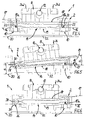
- each actuating rocker 8 optionally on two switch contact elements 10 (Fig. 4) or only on a switching contact element 10 (Fig. 5 and 6) acts.
- each actuating rocker 8 is expediently in their central area directly on the housing part 2 hinged about bearing elements 12.
- each switching arm 14 is optionally in one of at least two different layers can be assembled, the switching arm 14 - see FIGS. 4 to 6 - on the one hand two mutually opposite system levels 16, 17 for optional, position-dependent interaction with the respective switch contact element 10 and on the other hand two the connection levels 16, 17 respectively opposite connection levels 18, 19 for optional, position-dependent interaction defined with the associated operating rocker 8.
- the shift arm bridges 14 each exactly the space between the rocker switch 8 and the switch contact element or elements 10.
- the Switch arm 14 in position with the base plane 20 parallel Connection level 18 at both ends on one of each two switch contact elements 10.
- 6 is the Switch arm 14 also mounted so that the connection level 18 runs parallel to the base plane 20, but acts the switching arm 14 only has one end on a switching contact element 10 while he is elsewhere at a fixed, housing-side abutment 26 is supported. This is done the actuation of the switching contact element 10 by one-sided pressing on the operating rocker 8 on the Abutment 26 opposite side in the direction of arrow 24c.
- This support is preferably carried out here due to pivotable articulation.
- the shift arm points to this 14 at its end supported on the abutment 26
- the bearing receptacle 28 and the bearing journal (s) 30 locked together.
- Each switching contact element 10 is expediently on well-known rubber switching element is formed (so-called "SMD button”), which also serves as a spring element elastic resetting of the respective operating rocker 8 acts (via the switching arm 14).
- the switch contact elements 10 makes sense on a flat circuit board 32 arranged, this circuit board 32 the Switch base level 20 defined or at least to the base level 20 is arranged in parallel.
- the housing part 2 takes the invention Switch arms 14 on, for which a corresponding switch arm 14 Receiving chamber 34 is provided.
- the elongated, approximately rod-shaped switching arm 14 only needs essentially loosely in the required mounting position in the corresponding Receiving chamber 34 to be inserted, apart from the latchable pivot bearing 28, 30 according to FIG. 5.
- the housing part 2 can advantageously be an adapter for Connect the key switch 1 with a not shown Bus coupler of a common installation bus system form.
- the invention is not based on the illustrated and described Embodiments limited, but also includes all designs having the same effect in the sense of the invention. Furthermore, the invention is not yet based on the Claim 1 defined combination of features limited, but can also by any other combination of certain characteristics of all the individual characteristics disclosed overall be defined. This means that basically practically every single feature of claim 1 omitted or by at least one elsewhere in the Application disclosed single feature can be replaced. In this respect, claim 1 is only a first attempt at formulation to understand for an invention.
Landscapes
- Engineering & Computer Science (AREA)
- Manufacturing & Machinery (AREA)
- Push-Button Switches (AREA)
- Switches With Compound Operations (AREA)
Abstract
Description
- Fig. 1
- eine Perspektivansicht der Oberseite eines Gehäuseteils des erfindungsgemäßen Tastschalters mit daran schwenkbeweglich gelagerten Betätigungswippen,
- Fig. 2
- eine Perspektivansicht des Gehäuseteils von der Unterseite her,
- Fig. 3
- eine Perspektivansicht eines erfindungsgemäßen Schaltarms zum Einsetzen in das Gehäuseteil, und zwar in einer Anordnung zwischen einer der Betätigungswippen gemäß Fig. 1 und in Fig. 2 nicht dargestellten Schaltkontaktelementen,
- Fig. 4
- die Einzelteile nach Fig. 1 und 3 mit zusätzlichen Schaltkontaktelementen in einem zusammengesetzten Zustand und in einer schematischen Schnittdarstellung in der Ebene X-X gemäß Fig. 1, und zwar in einem ersten Anwendungsfall,
- Fig. 5
- eine Darstellung analog zu Fig. 4 in einem zweiten Anwendungsfall und
- Fig. 6
- eine Darstellung analog zu Fig. 4 bzw. 5 in einem dritten Anwendungsfall.
Claims (11)
- Elektrischer Tastschalter (1) mit mindestens einer kippbar gelagerten, auf mindestens ein Schaltkontaktelement (10) wirkenden Betätigungswippe (8),
dadurch gekennzeichnet, daß die Betätigungswippe (8) mittelbar über einen wahlweise in einer von mindestens zwei verschiedenen Lagen montierbaren Schaltarm (14) auf das bzw. jedes Schaltkontaktelement (10) wirkt, wobei der Schaltarm (14) einerseits zwei einander gegenüberliegende Anlageebenen (16,17) zum wahlweisen, lageabhängigen Zusammenwirken mit dem jeweiligen Schaltkontaktelement (10) sowie andererseits zwei den Anlageebenen (16,17) jeweils gegenüberliegende Verbindungsebenen (18,19) zum wahlweisen, lageabhängigen Zusammenwirken mit der Betätigungswippe (8) definiert, wobei je nach Lage des Schaltarms (14) die jeweils auf das/jedes Schaltkontaktelement (10) wirkende Anlageebene (16 oder 17) jedenfalls im wesentlichen parallel zu einer Schalter-Basisebene (20) verläuft, während die jeweils gegenüberliegende, mit der Betätigungswippe (8) zusammenwirkende Verbindungsebene (18 oder 19) zu der Schalter-Basisebene (20) entweder ebenfalls im wesentlichen parallel oder in einem bestimmten Winkel (α) schräg verläuft. - Tastschalter nach Anspruch 1,
dadurch gekennzeichnet, daß der Schaltarm (14) in seiner Lage mit zu der Schalter-Basisebene (20) im wesentlichen paralleler Verbindungsebene (18) beidendig auf jeweils eines von zwei Schaltkontaktelementen (10) wirkt. - Tastschalter nach Anspruch 1,
dadurch gekennzeichnet, daß der Schaltarm (14) in seiner Lage mit zu der Schalter-Basisebene (20) im wesentlichen paralleler Verbindungsebene (18) einendig auf das Schaltkontaktelement (10) wirkt und anderendig an einem ortsfesten Widerlager (26) abgestützt ist. - Tastschalter nach Anspruch 1,
dadurch gekennzeichnet, daß der Schaltarm (14) in seiner Lage mit zu der Schalter-Basisebene (20) in dem Winkel (α) schräg geneigt verlaufender Verbindungsebene (19) einendig auf das Schaltkontaktelement (10) wirkt und anderendig an einem ortsfesten Widerlager (26) abgestützt, vorzugsweise schwenkbeweglich angelenkt ist. - Tastschalter nach Anspruch 3 oder 4,
dadurch gekennzeichnet, daß der Schaltarm (14) an seinem an dem Widerlager (26) abgestützten Ende eine Lageraufnahme (28) aufweist, die mit mindestens einem ortsfesten Lagerzapfen (30) zusammenwirkt, wobei vorzugsweise die Lageraufnahme (28) und der/die Lagerzapfen (30) miteinander verrastbar sind. - Tastschalter nach einem der Ansprüche 1 bis 5,
dadurch gekennzeichnet, daß mindestens zwei Betätigungswippen (8) - eine Tastschalterkombination bildend - mit entsprechend zugehörigen Schaltkontaktelementen (10) und jeweils einem Schaltarm (14) parallel angeordnet sind. - Tastschalter nach einem der Ansprüche 1 bis 6,
dadurch gekennzeichnet, daß das/jedes Schaltkontaktelement (10) als Gummi-Schaltelement ausgebildet ist, das gleichzeitig auch als Federelement für die jeweilige Betätigungswippe (8) wirkt. - Tastschalter nach einem der Ansprüche 1 bis 7,
dadurch gekennzeichnet, daß das/jedes Schaltkontaktelement (10) auf einer Schaltplatine (32) angeordnet ist, wobei die Schaltplatine (32) die Schalter-Basisebene (20) definiert oder dazu parallel angeordnet ist. - Tastschalter nach einem der Ansprüche 1 bis 8,
gekennzeichnet durch ein den/jeden Schaltarm (14) aufnehmendes Gehäuseteil (2) mit mindestens einer Aufnahmekammer (34) für den jeweiligen Schaltarm (14). - Tastschalter nach Anspruch 9,
dadurch gekennzeichnet, daß das Gehäuseteil (2) einen Adapter zum Verbinden des Tastschalters (1) mit einem Bus-Ankoppler eines Installations-Bus-Systems bildet. - Tastschalter nach einem der Ansprüche 9 oder 10,
dadurch gekennzeichnet, daß die/jede Betätigungswippe (8) in ihrem mittigen Bereich unmittelbar an dem Gehäuseteil (2), insbesondere an dessen Oberseite (6), über Lagerelemente (12) schwenkbar angelenkt ist.
Applications Claiming Priority (2)
| Application Number | Priority Date | Filing Date | Title |
|---|---|---|---|
| DE29805719U | 1998-03-28 | ||
| DE29805719U DE29805719U1 (de) | 1998-03-28 | 1998-03-28 | Elektrischer Tastschalter |
Publications (2)
| Publication Number | Publication Date |
|---|---|
| EP0948010A2 true EP0948010A2 (de) | 1999-10-06 |
| EP0948010A3 EP0948010A3 (de) | 2000-07-12 |
Family
ID=8054977
Family Applications (1)
| Application Number | Title | Priority Date | Filing Date |
|---|---|---|---|
| EP99101255A Withdrawn EP0948010A3 (de) | 1998-03-28 | 1999-01-23 | Elektrischer Tastschalter |
Country Status (2)
| Country | Link |
|---|---|
| EP (1) | EP0948010A3 (de) |
| DE (1) | DE29805719U1 (de) |
Family Cites Families (3)
| Publication number | Priority date | Publication date | Assignee | Title |
|---|---|---|---|---|
| FR1340217A (fr) * | 1962-07-26 | 1963-10-18 | Merlin Gerin | Interrupteur |
| DE9406434U1 (de) * | 1994-04-18 | 1994-09-08 | Gira Giersiepen Gmbh & Co Kg, 42477 Radevormwald | Elektrischer Tastschalter |
| DE29612262U1 (de) * | 1996-07-15 | 1996-09-12 | Maihöfer, Gerd, 58675 Hemer | Doppelhub-Wippschalter mit Elastomer Schaltelementen |
-
1998
- 1998-03-28 DE DE29805719U patent/DE29805719U1/de not_active Expired - Lifetime
-
1999
- 1999-01-23 EP EP99101255A patent/EP0948010A3/de not_active Withdrawn
Also Published As
| Publication number | Publication date |
|---|---|
| EP0948010A3 (de) | 2000-07-12 |
| DE29805719U1 (de) | 1998-05-28 |
Similar Documents
| Publication | Publication Date | Title |
|---|---|---|
| EP0959529A2 (de) | Elektrische Anschlussbaueinheit | |
| DE2243673C3 (de) | Elektrischer Schalter, insbesondere Mikroschalter | |
| DE3247319A1 (de) | Elektrischer drucktastenschalter mit einem schwenkbar gelagerten druckbuegel | |
| EP0678885B1 (de) | Elektrischer Tastschalter | |
| DE4018978C2 (de) | Schiebeschalter | |
| DE2847772A1 (de) | Elektrischer schalter | |
| AT409198B (de) | Schaltmechanik für einen tastschalter | |
| DE3219294C2 (de) | ||
| DE2118633A1 (de) | Elektromagnetisches Relais | |
| DE19811230C1 (de) | Große, mehrere kleine Tastenfelder abdeckende Drucktaste für ein Keyboard | |
| EP0948010A2 (de) | Elektrischer Tastschalter | |
| EP1467390A1 (de) | Tastenblock zum Einsetzen in eine Bedienfläche eines Haushaltsgerätes | |
| DE3240940A1 (de) | Taste zum schliessen elektrischer kontakte | |
| DE10055035C2 (de) | Lasttrennschalter mit mindestens einem Sicherungshalter | |
| DE29920404U1 (de) | Elektrischer Installationsschalter sowie Bauteilsystem und Glimmlampe für einen elektrischen Installationsschalter | |
| EP1376631B1 (de) | Befestigung mindestens einer Betätigungswippe an der Schaltwippe eines elektrischen Schaltgerätes | |
| EP0922290B1 (de) | Bewegbare schaltkontaktanordnung mit einem kontakthebel aufnehmenden kontakthebelträger | |
| DE2413897B2 (de) | Elektrischer installationsschalter | |
| DE29520909U1 (de) | Elektrisches Schaltgerät | |
| EP0890969A2 (de) | Kontaktkörper zur Aufnahme eines Kontaktmessers eines Sicherungseinsatzes | |
| WO2000022305A1 (de) | Elektrisches gerät mit einem verbindungsclip und einer verbindungsclipaufnahme zur verbindung mit einem zweiten elektrischen gerät | |
| DE102009037408B4 (de) | Betätigungseinrichtung | |
| DE2511510A1 (de) | Elektrischer schalter | |
| EP3654473B1 (de) | Elektrischer schalter | |
| EP0858088B1 (de) | Elektrisches Schaltgerät |
Legal Events
| Date | Code | Title | Description |
|---|---|---|---|
| PUAI | Public reference made under article 153(3) epc to a published international application that has entered the european phase |
Free format text: ORIGINAL CODE: 0009012 |
|
| AK | Designated contracting states |
Kind code of ref document: A2 Designated state(s): AT BE DE NL |
|
| AX | Request for extension of the european patent |
Free format text: AL;LT;LV;MK;RO;SI |
|
| TCNL | Nl: translation of patent claims filed | ||
| PUAL | Search report despatched |
Free format text: ORIGINAL CODE: 0009013 |
|
| AK | Designated contracting states |
Kind code of ref document: A3 Designated state(s): AT BE CH CY DE DK ES FI FR GB GR IE IT LI LU MC NL PT SE |
|
| AX | Request for extension of the european patent |
Free format text: AL;LT;LV;MK;RO;SI |
|
| 17P | Request for examination filed |
Effective date: 20000621 |
|
| AKX | Designation fees paid |
Free format text: AT BE DE NL |
|
| 17Q | First examination report despatched |
Effective date: 20020426 |
|
| GRAH | Despatch of communication of intention to grant a patent |
Free format text: ORIGINAL CODE: EPIDOS IGRA |
|
| RAP1 | Party data changed (applicant data changed or rights of an application transferred) |
Owner name: GIRA GIERSIEPEN GMBH & CO. KG |
|
| STAA | Information on the status of an ep patent application or granted ep patent |
Free format text: STATUS: THE APPLICATION IS DEEMED TO BE WITHDRAWN |
|
| 18D | Application deemed to be withdrawn |
Effective date: 20030910 |