EP0946317B1 - Platten mit keramischen schichten für das walzengiessverfahren und verfahren zu deren herstellung - Google Patents
Platten mit keramischen schichten für das walzengiessverfahren und verfahren zu deren herstellung Download PDFInfo
- Publication number
- EP0946317B1 EP0946317B1 EP97935759A EP97935759A EP0946317B1 EP 0946317 B1 EP0946317 B1 EP 0946317B1 EP 97935759 A EP97935759 A EP 97935759A EP 97935759 A EP97935759 A EP 97935759A EP 0946317 B1 EP0946317 B1 EP 0946317B1
- Authority
- EP
- European Patent Office
- Prior art keywords
- casting
- ceramic
- insert
- silica
- alumina
- Prior art date
- Legal status (The legal status is an assumption and is not a legal conclusion. Google has not performed a legal analysis and makes no representation as to the accuracy of the status listed.)
- Expired - Lifetime
Links
- 239000000919 ceramic Substances 0.000 title claims abstract description 56
- 238000009749 continuous casting Methods 0.000 title claims abstract description 9
- 238000000034 method Methods 0.000 title claims description 7
- 238000004519 manufacturing process Methods 0.000 title claims description 6
- 238000005266 casting Methods 0.000 claims abstract description 73
- MCMNRKCIXSYSNV-UHFFFAOYSA-N Zirconium dioxide Chemical compound O=[Zr]=O MCMNRKCIXSYSNV-UHFFFAOYSA-N 0.000 claims abstract description 48
- 239000000463 material Substances 0.000 claims abstract description 48
- PNEYBMLMFCGWSK-UHFFFAOYSA-N aluminium oxide Inorganic materials [O-2].[O-2].[O-2].[Al+3].[Al+3] PNEYBMLMFCGWSK-UHFFFAOYSA-N 0.000 claims abstract description 33
- 230000009974 thixotropic effect Effects 0.000 claims abstract description 17
- 229910010293 ceramic material Inorganic materials 0.000 claims abstract description 16
- 239000000835 fiber Substances 0.000 claims abstract 5
- 239000000203 mixture Substances 0.000 claims description 16
- VYPSYNLAJGMNEJ-UHFFFAOYSA-N Silicium dioxide Chemical compound O=[Si]=O VYPSYNLAJGMNEJ-UHFFFAOYSA-N 0.000 claims description 14
- 239000011819 refractory material Substances 0.000 claims description 14
- 150000001875 compounds Chemical class 0.000 claims description 10
- 229910052751 metal Inorganic materials 0.000 claims description 9
- 239000002184 metal Substances 0.000 claims description 9
- 229910052681 coesite Inorganic materials 0.000 claims description 7
- 229910052593 corundum Inorganic materials 0.000 claims description 7
- 229910052906 cristobalite Inorganic materials 0.000 claims description 7
- 239000000377 silicon dioxide Substances 0.000 claims description 7
- 229910052682 stishovite Inorganic materials 0.000 claims description 7
- 229910052905 tridymite Inorganic materials 0.000 claims description 7
- 229910001845 yogo sapphire Inorganic materials 0.000 claims description 7
- 230000008878 coupling Effects 0.000 claims description 4
- 238000010168 coupling process Methods 0.000 claims description 4
- 238000005859 coupling reaction Methods 0.000 claims description 4
- 238000010304 firing Methods 0.000 claims description 4
- 230000002093 peripheral effect Effects 0.000 claims description 3
- 238000004026 adhesive bonding Methods 0.000 claims description 2
- 239000004411 aluminium Substances 0.000 claims description 2
- 229910052782 aluminium Inorganic materials 0.000 claims description 2
- XAGFODPZIPBFFR-UHFFFAOYSA-N aluminium Chemical compound [Al] XAGFODPZIPBFFR-UHFFFAOYSA-N 0.000 claims description 2
- 239000010703 silicon Substances 0.000 claims description 2
- 229910052710 silicon Inorganic materials 0.000 claims description 2
- 239000012535 impurity Substances 0.000 claims 5
- WHOPEPSOPUIRQQ-UHFFFAOYSA-N oxoaluminum Chemical compound O1[Al]O[Al]1 WHOPEPSOPUIRQQ-UHFFFAOYSA-N 0.000 claims 1
- 239000004568 cement Substances 0.000 description 4
- 239000002131 composite material Substances 0.000 description 3
- 239000007787 solid Substances 0.000 description 3
- 239000000126 substance Substances 0.000 description 3
- 230000015572 biosynthetic process Effects 0.000 description 2
- 238000007711 solidification Methods 0.000 description 2
- 230000008023 solidification Effects 0.000 description 2
- 229910000589 SAE 304 stainless steel Inorganic materials 0.000 description 1
- 206010039509 Scab Diseases 0.000 description 1
- 229910000831 Steel Inorganic materials 0.000 description 1
- 230000008602 contraction Effects 0.000 description 1
- 239000006185 dispersion Substances 0.000 description 1
- 230000008595 infiltration Effects 0.000 description 1
- 238000001764 infiltration Methods 0.000 description 1
- JEIPFZHSYJVQDO-UHFFFAOYSA-N iron(III) oxide Inorganic materials O=[Fe]O[Fe]=O JEIPFZHSYJVQDO-UHFFFAOYSA-N 0.000 description 1
- 239000011214 refractory ceramic Substances 0.000 description 1
- 239000010959 steel Substances 0.000 description 1
- XLYOFNOQVPJJNP-UHFFFAOYSA-N water Substances O XLYOFNOQVPJJNP-UHFFFAOYSA-N 0.000 description 1
Images


Classifications
-
- B—PERFORMING OPERATIONS; TRANSPORTING
- B22—CASTING; POWDER METALLURGY
- B22D—CASTING OF METALS; CASTING OF OTHER SUBSTANCES BY THE SAME PROCESSES OR DEVICES
- B22D11/00—Continuous casting of metals, i.e. casting in indefinite lengths
- B22D11/06—Continuous casting of metals, i.e. casting in indefinite lengths into moulds with travelling walls, e.g. with rolls, plates, belts, caterpillars
-
- B—PERFORMING OPERATIONS; TRANSPORTING
- B22—CASTING; POWDER METALLURGY
- B22D—CASTING OF METALS; CASTING OF OTHER SUBSTANCES BY THE SAME PROCESSES OR DEVICES
- B22D11/00—Continuous casting of metals, i.e. casting in indefinite lengths
- B22D11/06—Continuous casting of metals, i.e. casting in indefinite lengths into moulds with travelling walls, e.g. with rolls, plates, belts, caterpillars
- B22D11/0637—Accessories therefor
- B22D11/0648—Casting surfaces
- B22D11/066—Side dams
-
- Y—GENERAL TAGGING OF NEW TECHNOLOGICAL DEVELOPMENTS; GENERAL TAGGING OF CROSS-SECTIONAL TECHNOLOGIES SPANNING OVER SEVERAL SECTIONS OF THE IPC; TECHNICAL SUBJECTS COVERED BY FORMER USPC CROSS-REFERENCE ART COLLECTIONS [XRACs] AND DIGESTS
- Y10—TECHNICAL SUBJECTS COVERED BY FORMER USPC
- Y10T—TECHNICAL SUBJECTS COVERED BY FORMER US CLASSIFICATION
- Y10T428/00—Stock material or miscellaneous articles
- Y10T428/22—Nonparticulate element embedded or inlaid in substrate and visible
Definitions
- the present invention relates to an improvement in refractory plates for apparatuses for the continuous casting of flat, thin products and, more particularly to an improvement in refractory plates consisting in inserting thereon ceramic inserts against wear.
- JP-A-7068352 is disclosed a ceramic plate which is mounted on water cooled metallic case in order to make thermal deformation and side wear small in a casting twin rolls apparatus.
- Refractory plates for the lateral containment of molten metal, in an apparatus for the continuous casting of thin, flat products and having ceramic inserts thereon are already known.
- the aim of the present invention is to provide improved refractory plates having inserts of ceramic material that solve the abovementioned problems of reduced planarity, of a time-consuming and difficult production of the same, and of the generation of fissures in the areas between inserts and refractory castings.
- Another aim of the present invention is to provide low-cost improved refractory plates with ceramic material inserts.
- a further object of the present invention is to provide a process for the production of such improved refractory plates.
- improved refractory plates for the lateral containment in apparatuses for the continuous casting characterised in that they comprise:
- the present invention provides a process for the production of refractory plates with ceramic inserts, characterised in that it comprises the following steps:
- Fig. 1 shows schematically an apparatus for the continuous casting of flat, thin products.
- the apparatus comprises a pair of counter-rotating rolls 1 and 2, and with their rotation axes spaced by a distance greater than the sum of their radiuses.
- the apparatus comprises a pair of counter-rotating rolls 1 and 2, and with their rotation axes spaced by a distance greater than the sum of their radiuses.
- At both the lateral faces of said rolls 1 and 2 there are arranged two flat walls 3 and 4 which have respective refractory plates 5 (better shown hereinafter) for the lateral containment of molten metal 6 cast between the rolls 1 and 2.
- the arrangement is such to obtain a flat product 7 following the rotation of the rolls 1 and 2.
- FIG. 2 shows a perspective view that illustrates partially the plate according to the invention.
- the plate 5 is constituted of a plurality of inserts 8 of a ceramic material arranged along the contacting arc between the edges of the rolls 1, 2 (schematically shown by means of the lines A-A) and the surface of the plate.
- the arrangement of the inserts 8 is such so that they assume a "Y"-shape on the plate 5.
- a first casting 9 of a silica-alumina refractory material containing ceramic fibres is provided.
- a silica-alumina refractory material containing ceramic fibres is provided.
- Such a compound has an extremely low thermal conductivity, avoiding thus the dispersion of heat towards the exterior.
- ZrO 2 Zirconia
- joints 11 for the thermal expansion (having the shape of elongated elements) constituted of highly refractory ceramic fibres, arranged for compensating the different thermal expansion between the inserts 8 and the adjacent castings 9 and 10, respectively, thus avoiding the formation of possible spaces or fissures that might constitute nuclei of cooled metal, with the consequences disclosed hereinabove.
- a third casting 12 of a thixotropic material having a high contents of SiC providing the support for the abovementioned inserts 8 and the castings 9 and 10, respectively by covering them on their back and entirely.
- Said casting 12 of a thixotropic material has a high thermal conductivity and high mechanical characteristics.
- FIG. 3 shows a cross section of the plate, taken along the line A-A of Fig. 2.
- the third casting 12 of material having a high contents of SiC constitutes the support both for the inserts 8 and for the castings 9 and 10, respectively.
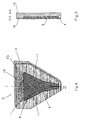
- FIGs. 4 and 5 show a perspective view a cross sectional view along the line A-A, respectively, of a second embodiment of the present invention.
- the plate has a single insert 8 in a ceramic material and in the shape of substantially a triangle.
- Refractory plates have been obtained by means of a casting material and inserts in a ceramic material, having the following features:
- joints for the thermal expansion have been inserted between the inserts and the castings, constituted essentially of the following compound, expressed as a percentage in weight with respect to the total weight of the mixture:
- Refractory plates have been obtained by means of casting a refractory material constituted as in the former example and inserts of a ceramic material, the inserts having the following composition, expressed in percentage in weight with respect to the total weight of the mixture:
- the present embodiment allows to obtain a monolithic composite plate in which all the components are assembled each other with continuity thanks to the formation of chemical bonds having high mechanical characteristics. In this way there is avoided the possibility of occurring fissures between a material and another, as in the case of a refractory cement and, consequently, the problems which cause undesired solidifications which would entail the inconvenience that have been disclosed hereinbefore.
Landscapes
- Engineering & Computer Science (AREA)
- Mechanical Engineering (AREA)
- Compositions Of Oxide Ceramics (AREA)
- Ceramic Products (AREA)
- Laminated Bodies (AREA)
- Continuous Casting (AREA)
- Press-Shaping Or Shaping Using Conveyers (AREA)
- Devices For Post-Treatments, Processing, Supply, Discharge, And Other Processes (AREA)
- Preparation Of Clay, And Manufacture Of Mixtures Containing Clay Or Cement (AREA)
Claims (8)
- Platten (5) für das seitliche Einschließen in Vorrichtungen zum Stranggießen, die umfassen:wobei die Anordnung so ist, daß der wenigstens eine keramische Einsatz (3) an dem dritten Gußteil (12) aus einem thixotrophischen Material so angeordnet ist, daß er eine im wesentlichen dreieckige Form annimmt, das erste Siliziumoxid-Aluminiumoxid-Gußteil (9) auf Basis eines keramischen Fasermaterials an dem dritten Gußteil (12) an dem äußeren Bereich in bezug auf den wenigstens einen keramischen Einsatz (8) angeordnet ist, das zweite Gußteil (9) aus Siliziumoxid-Aluminiumoxid-Material mit einem hohen Gehalt an ZrO2 an dem dritten Gußteil (12) aus einem thixotrophischen Material im wesentlichen im mittleren Abschnitt der Platte (5) angeordnet ist, der durch den wenigstens einen keramischen Einsatz (8) gebildet wird, und die Vielzahl von Verbindungsstellen (11) aus keramischen Fasern für die Wärmeausdehnung an den Kontaktflächen zwischen dem wenigstens einen keramischen Einsatz (8) und wenigstens dem ersten, dem zweiten oder dem dritten Gußteil (9, 10, 12) angeordnet ist.wenigstens einen Einsatz (8) aus einem keramischen Material;eine Vielzahl von Verbindungsstellen (11) für die Wärmeausdehnung, wobei die Verbindungsstellen aus einem keramischen Fasermaterial bestehen;ein erstes Gußteil (9) aus einem Siliziumoxid-Aluminiumoxid-Material, das keramische Fasern enthält;ein zweites Gußteil (10) aus einem Siliziumoxid-Aluminiumoxid-Material mit einem hohen Gehalt an ZrO2; undein drittes Gußteil (12) aus einem thixotrophischen Material auf SiC-Basis;
- Platten nach Anspruch 1, wobei das dritte Gußteil (12) aus einem thixotrophischen Material auf SiC-Basis, in Gewichtsprozent ausgedrückt, ein Gemisch der folgenden Bestandteile enthält:
- Al2O3
- 5 bis 15 %
- SiO2
- 2 bis 4,5 %
- SiC
- 80 bis 95 %;
- Platten nach Anspruch 1 oder 2, wobei das zweite Gußteil (10) aus einem Siliziumoxid-Aluminiumoxid-Material mit einem hohen Gehalt an ZrO2, in Gewichtsprozent ausgedrückt, ein Gemisch der folgenden Verbindungen enthält:
- ZrO2
- 40 bis 60 %
- Al2O3
- 25 bis 40 %
- SiO2
- 15 bis 40 %;
- Platten nach einem der vorangehenden Ansprüche, wobei das erste Siliziumoxid-Aluminiumoxid-Gußteil (9) auf der Basis von keramischen Fasern, in Gewichtsprozent ausgedrückt, ein Gemisch der folgenden Verbindungen enthält:
- Al2O3
- 40 bis 50 %
- SiO2
- 30 bis 40 %;
- Fe2O2
- 2,5 bis 4,5 %
- Platten nach einem der vorangehenden Ansprüche, wobei jeder Einsatz (8) der Vielzahl keramischer Einsätze, in Gewichtsprozent ausgedrückt, ein Gemisch der folgenden Verbindungen in bezug auf das Gesamtgewicht des Gemischs enthält:
- BN
- 20 bis 55 %; und wenigstens eine der folgenden Verbindungen:
- ZrO2
- 40 bis 60 %
- SiC
- 2,5 bis 7,5 %;
- Sialon (Silicium-und-Aluminium-Oxinitirid)
- 55 bis 90 %;
- Platten nach einem der vorangehenden Ansprüche, wobei die Vielzahl von Verbindungsstellen (11) aus keramischen Fasern für die Wärmeausdehnung, in Gewichtsprozent ausgedrückt, ein Gemisch der folgenden Verbindungen umfaßt:
- Al2O2
- 80 bis 95 %
- SiC
- 2 bis 25 %
- Verfahren zum Herstellen verbesserter feuerfester Platten (5) mit keramischen Einsätzen (8) nach einem der Ansprüche 1-6, dadurch gekennzeichnet, daß es die folgenden Schritte umfaßt:Positionieren und optimales Verbinden durch Ankleben wenigstens eines Einsatzes (8) aus keramischem Material am Boden einer Form;Positionieren einer Vielzahl von Verbindungsstellen (11), die aus keramischen Fasern bestehen, mit optimierter Verbindung an den Umfangswänden des wenigstens einen Einsatzes (8) aus keramischem Material;Ausführen eines ersten Gußteils (9) aus einem feuerfesten Material, das im wesentlichen aus einem Gemisch aus Siliziumoxid und Aluminiumoxid sowie keramischen Fasern besteht, am äußeren Teil des wenigstens einen keramischen Einsatzes (8);Ausführen eines zweiten Gußteils (10) aus einem feuerfesten Siliziumoxid-Aluminiumoxid-Material mit einem hohen Gehalt an ZrO2 am mittleren Teil der Platte (5), das innen durch den wenigstens einen keramischen Einsatz (8) begrenzt wird;Ausführen eines dritten Gußteils (12) aus einem feuerfesten thixotrophischen Material mit einem hohen Gehalt an SiC über dem wenigstens einen keramischen Einsatz (8) in bezug auf das erste Gußteil (9) aus feuerfestem Material und das zweite Gußteil (10) aus feuerfestem Material mit einem hohen Gehalt an ZrO2;Entnehmen der so hergestellten Platte (5) aus der Form nach einem Zeitraum von wenigstens 24 Stunden;Wärmebehandlung der Platte (5) bei 110°C über einen Zeitraum von wenigstens 24 Stunden; undNiedrigtemperatur-Brennen der Platte (5) bei wenigstens 400°C über einen Zeitraum von wenigstens einer Stunde.
- Vorrichtung zum Stranggießen von flachen dünnen Körpern (7), die umfaßt:wobei die Platten (5) dadurch gekennzeichnet sind, daß sie umfassen:wenigstens ein Paar gegenläufiger Walzen (1, 2), deren Längsachsen parallel in einem Abstand angeordnet sind, der größer ist als die Summe ihrer Radien; undwenigstens ein Paar feuerfester Platten (5), die das geschmolzene Metall (6) einschließen und sich an den Basen des Paars Walzen (1, 2) befinden;wobei die Anordnung so ist, daß der wenigstens eine keramische Einsatz (8) an dem dritten Gußteil (12) aus thixotrophischem Material so angeordnet ist, daß eine im wesentlichen dreieckige Form entsteht, das erste Siliziumoxid-Aluminiumoxid-Gußteil (9) mit keramischen Fasern an dem dritten Gußteil (12) an dem äußeren Bereich in bezug auf den wenigstens einen keramischen Einsatz (8) angeordnet ist, das zweite Gußteil (10) aus Material mit einem hohen Gehalt an ZrO2 an dem dritten Gußteil (12) aus thixotrophischem Material im wesentlichen im mittleren Bereich angeordnet ist, der durch den wenigstens einen keramischen Einsatz (8) gebildet wird, und die Vielzahl von Verbindungsstellen (11) aus keramischen Fasern an den Kontaktflächen zwischen dem wenigstens einen keramischen Einsatz (8) und wenigstens dem ersten, dem zweiten oder dem dritten Gußteil (9, 10, 11) angeordnet ist.wenigstens einen Einsatz (8) aus einem keramischem Material;eine Vielzahl von Verbindungsstellen (11) für die Wärmeausdehnung, die aus einem keramischen Fasermaterial bestehen;ein erstes Gußteil (9) aus einem Siliziumoxid-Aluminiumoxid-Material auf Basis von keramischen Fasern;ein zweites Gußteil (10) aus einem Siliziumoxid-Aluminiumoxid-Material mit einem hohen Gehalt an ZrO2; undein drittes Gußteil (12) aus einem thixotrophischen Material auf SiC-Basis;
Applications Claiming Priority (3)
| Application Number | Priority Date | Filing Date | Title |
|---|---|---|---|
| ITRM960552 | 1996-07-31 | ||
| IT96RM000552A IT1284201B1 (it) | 1996-07-31 | 1996-07-31 | Piastre con riporti ceramici antiusura per macchine per colata conntinua di corpi piani sottili e procedimento per la loro |
| PCT/IT1997/000195 WO1998004369A1 (en) | 1996-07-31 | 1997-07-30 | Plates with ceramic layers for apparatuses for the continuous casting of flat thin products and process for the manufacture thereof |
Publications (2)
| Publication Number | Publication Date |
|---|---|
| EP0946317A1 EP0946317A1 (de) | 1999-10-06 |
| EP0946317B1 true EP0946317B1 (de) | 2000-05-31 |
Family
ID=11404375
Family Applications (1)
| Application Number | Title | Priority Date | Filing Date |
|---|---|---|---|
| EP97935759A Expired - Lifetime EP0946317B1 (de) | 1996-07-31 | 1997-07-30 | Platten mit keramischen schichten für das walzengiessverfahren und verfahren zu deren herstellung |
Country Status (12)
| Country | Link |
|---|---|
| US (1) | US6378598B1 (de) |
| EP (1) | EP0946317B1 (de) |
| JP (1) | JP3042896B2 (de) |
| KR (1) | KR100325557B1 (de) |
| AT (1) | ATE193471T1 (de) |
| AU (1) | AU3863597A (de) |
| DE (1) | DE69702211T2 (de) |
| ID (1) | ID17970A (de) |
| IT (1) | IT1284201B1 (de) |
| MY (1) | MY118910A (de) |
| WO (1) | WO1998004369A1 (de) |
| ZA (1) | ZA976786B (de) |
Cited By (1)
| Publication number | Priority date | Publication date | Assignee | Title |
|---|---|---|---|---|
| WO2009030411A1 (de) * | 2007-08-28 | 2009-03-12 | Esk Ceramics Gmbh & Co. Kg | Seitenplatte für das dünnbandgiessen von stahl |
Families Citing this family (22)
| Publication number | Priority date | Publication date | Assignee | Title |
|---|---|---|---|---|
| IT1302959B1 (it) * | 1998-12-31 | 2000-10-10 | Acciai Speciali Terni Spa | Piastre refrattarie per macchine di colata continua di corpi pianisottili. |
| JP3684138B2 (ja) * | 2000-05-17 | 2005-08-17 | 新日本製鐵株式会社 | 双ドラム式連鋳サイド堰用セラミックプレート材 |
| AT412195B (de) * | 2002-06-25 | 2004-11-25 | Voest Alpine Ind Anlagen | Verfahren zur erzeugung eines metallbandes mit einer zweiwalzengiesseinrichtung |
| FR2842130B1 (fr) * | 2002-07-12 | 2004-10-15 | Usinor | Face laterale pour installation de coulee continue de bandes metalliques entre deux cylindres |
| CH696138A5 (de) * | 2002-10-04 | 2007-01-15 | Main Man Inspiration Ag | Dichtplatte zur Seitenabdichtung eines zwischen zwei Giessrollen einer Bandgiessmaschine gebildeten Giessspaltes. |
| DE10341250B3 (de) * | 2003-09-08 | 2005-05-25 | Thyssenkrupp Nirosta Gmbh | Verfahren zum Betrieb einer Zweiwalzengießvorrichtung |
| DE10341252B3 (de) * | 2003-09-08 | 2005-01-13 | Thyssenkrupp Nirosta Gmbh | Verfahren zum Betrieb einer Zweiwalzengießvorrichtung und Zweiwalzengießvorrichtung |
| DE10341251B4 (de) * | 2003-09-08 | 2005-06-30 | Thyssenkrupp Nirosta Gmbh | Verfahren zum Betrieb einer Zweiwalzengießvorrichtung |
| DE10341249B4 (de) * | 2003-09-08 | 2005-06-30 | Thyssenkrupp Nirosta Gmbh | Seitenplatte zum Abdichten eines zwischen den Gießwalzen einer Zweiwalzengießvorrichtung gebildeten Gießspalts, Zweiwalzengießvorrichtung und Verfahren zu ihrem Betrieb |
| US7128063B2 (en) * | 2004-07-21 | 2006-10-31 | Gm Global Technology Operations, Inc. | HCCI engine combustion control |
| CH697156A5 (de) * | 2004-09-17 | 2008-05-30 | Main Man Inspiration Ag | Seitenabdichtung eines zwischen zwei Giessrollen einer Bandgiessmaschine gebildeten Giessspaltes. |
| US7556084B2 (en) * | 2006-03-24 | 2009-07-07 | Nucor Corporation | Long wear side dams |
| US8042601B2 (en) * | 2006-03-24 | 2011-10-25 | Nucor Corporation | Side dam with insert |
| DE102007041263A1 (de) | 2007-08-30 | 2009-03-05 | Thyssenkrupp Nirosta Gmbh | Vorrichtung und Verfahren zum Gießen von Bändern aus einer Metallschmelze, insbesondere einer Stahlschmelze |
| JP5199227B2 (ja) * | 2009-12-15 | 2013-05-15 | 日立造船株式会社 | 波除用フラップゲートの起立状態保持機構 |
| JP5837758B2 (ja) | 2011-04-27 | 2015-12-24 | キャストリップ・リミテッド・ライアビリティ・カンパニー | 双ロール鋳造装置及びその制御方法 |
| WO2013106609A2 (en) | 2012-01-11 | 2013-07-18 | Saint-Gobain Ceramics & Plastics, Inc. | Refractory object and process of forming a glass sheet using the refractory object |
| US20140008032A1 (en) * | 2012-07-01 | 2014-01-09 | Nucor Corporation | Side dam with insert |
| CN115806439A (zh) * | 2015-02-24 | 2023-03-17 | 圣戈本陶瓷及塑料股份有限公司 | 耐火制品和制备方法 |
| US10046384B2 (en) | 2015-09-30 | 2018-08-14 | Nucor Corporation | Side dam with pocket |
| CN115626828A (zh) | 2017-10-20 | 2023-01-20 | 飞罗得材料技术股份有限公司 | 陶瓷、探针引导构件、探针卡及封装检查用插座 |
| CN120056248B (zh) * | 2025-04-28 | 2025-07-08 | 宜阳红星陶瓷有限公司 | 一种陶瓷坯自动成型设备 |
Family Cites Families (7)
| Publication number | Priority date | Publication date | Assignee | Title |
|---|---|---|---|---|
| JPH03118945A (ja) * | 1989-10-02 | 1991-05-21 | Nippon Steel Corp | 双ロール式連続鋳造機 |
| JPH03207554A (ja) * | 1990-01-05 | 1991-09-10 | Nippon Steel Corp | ツインドラム式連続鋳造機のサイド堰 |
| FR2671991A1 (fr) * | 1991-01-25 | 1992-07-31 | Usinor Sacilor | Materiau refractaire pour petite face d'une installation de coulee continue des metaux entre cyclindres, et petite face ainsi realisee. |
| JP3025135B2 (ja) * | 1993-09-01 | 2000-03-27 | 黒崎窯業株式会社 | 双ドラム式連続鋳造用のサイド堰とその製造方法 |
| FR2721843B1 (fr) * | 1994-06-30 | 1996-08-30 | Unisor Sacilor | Disposition de coulee continue entre cylindres a parois d'obturation laterale appliquees |
| US6152210A (en) * | 1994-10-14 | 2000-11-28 | Ishikawajima-Harima Heavy Industries Company Limited | Metal casting |
| FR2765504B1 (fr) * | 1997-07-04 | 1999-08-20 | Usinor | Face laterale d'obturation de l'espace de coulee d'une installation de coulee continue entre cylindres de bandes minces metalliques |
-
1996
- 1996-07-31 IT IT96RM000552A patent/IT1284201B1/it active IP Right Grant
-
1997
- 1997-07-30 WO PCT/IT1997/000195 patent/WO1998004369A1/en not_active Ceased
- 1997-07-30 DE DE69702211T patent/DE69702211T2/de not_active Expired - Fee Related
- 1997-07-30 MY MYPI97003482A patent/MY118910A/en unknown
- 1997-07-30 ZA ZA9706786A patent/ZA976786B/xx unknown
- 1997-07-30 AT AT97935759T patent/ATE193471T1/de not_active IP Right Cessation
- 1997-07-30 US US09/230,566 patent/US6378598B1/en not_active Expired - Fee Related
- 1997-07-30 AU AU38635/97A patent/AU3863597A/en not_active Abandoned
- 1997-07-30 JP JP10508672A patent/JP3042896B2/ja not_active Expired - Fee Related
- 1997-07-30 KR KR1019997000845A patent/KR100325557B1/ko not_active Expired - Fee Related
- 1997-07-30 EP EP97935759A patent/EP0946317B1/de not_active Expired - Lifetime
- 1997-07-31 ID IDP972664A patent/ID17970A/id unknown
Cited By (1)
| Publication number | Priority date | Publication date | Assignee | Title |
|---|---|---|---|---|
| WO2009030411A1 (de) * | 2007-08-28 | 2009-03-12 | Esk Ceramics Gmbh & Co. Kg | Seitenplatte für das dünnbandgiessen von stahl |
Also Published As
| Publication number | Publication date |
|---|---|
| JP3042896B2 (ja) | 2000-05-22 |
| WO1998004369A1 (en) | 1998-02-05 |
| ID17970A (id) | 1998-02-12 |
| JP2000500704A (ja) | 2000-01-25 |
| MY118910A (en) | 2005-02-28 |
| ITRM960552A1 (it) | 1998-01-31 |
| ATE193471T1 (de) | 2000-06-15 |
| KR100325557B1 (ko) | 2002-03-06 |
| DE69702211T2 (de) | 2001-02-22 |
| AU3863597A (en) | 1998-02-20 |
| ITRM960552A0 (de) | 1996-07-31 |
| DE69702211D1 (de) | 2000-07-06 |
| KR20000029741A (ko) | 2000-05-25 |
| US6378598B1 (en) | 2002-04-30 |
| EP0946317A1 (de) | 1999-10-06 |
| IT1284201B1 (it) | 1998-05-08 |
| ZA976786B (en) | 1998-02-11 |
Similar Documents
| Publication | Publication Date | Title |
|---|---|---|
| US6378598B1 (en) | Plates for use in continuous casting process for the manufacture thereof | |
| US6667263B1 (en) | Composite material | |
| EP0076577B1 (de) | Rinne für Metallschmelzen | |
| CN87101798A (zh) | 耐火模制件,尤其是滑动闸门的闸板 | |
| US4202148A (en) | Method of making thick-walled refractory fiber modules and the product formed thereby | |
| AU751827B2 (en) | Refractory plates for continuous casting machines of thin flat products | |
| US4483946A (en) | Refractory, heat-insulating liner | |
| US1817421A (en) | Lining brick for rotary cement kilns | |
| GB2085133A (en) | Refractory linings for metallurgical vessels | |
| JPH09263819A (ja) | 転炉ボトムの耐火物施工方法 | |
| JPH0412065A (ja) | 二層構造耐火物 | |
| JP2704250B2 (ja) | 誘導炉用不定形耐火物 | |
| SU722878A1 (ru) | Огнеупорна масса | |
| JP2727937B2 (ja) | 高炉炉体冷却用スティーブクーラの鋳包み方法 | |
| ZA200103709B (en) | Composite material. | |
| WO1990011377A1 (en) | Consumable furnace components | |
| JPH0716784B2 (ja) | 鋳込み用取鍋およびタンディッシュ | |
| JPH0527040U (ja) | 加熱炉用スキツドパイプ | |
| JPH02165863A (ja) | 入れ底型の取鍋底部の内張構造 | |
| KR880001934B1 (ko) | 하이 알루미나(High-Alumina)질 내화물로 캐스팅(Casting)된 평면턴디쉬 | |
| WO2001094056A1 (en) | A slide gate plate system reinforced with steel fibre | |
| JPH1035844A (ja) | コンベアベルトおよびその製造法 | |
| JPH0723254B2 (ja) | 耐火材料 | |
| WO1992019399A1 (en) | Insert for vessels or conduits containing molten metal | |
| Mccallen | High strength insulation for steel ladles |
Legal Events
| Date | Code | Title | Description |
|---|---|---|---|
| PUAI | Public reference made under article 153(3) epc to a published international application that has entered the european phase |
Free format text: ORIGINAL CODE: 0009012 |
|
| 17P | Request for examination filed |
Effective date: 19990202 |
|
| AK | Designated contracting states |
Kind code of ref document: A1 Designated state(s): AT DE FR GB |
|
| GRAG | Despatch of communication of intention to grant |
Free format text: ORIGINAL CODE: EPIDOS AGRA |
|
| GRAG | Despatch of communication of intention to grant |
Free format text: ORIGINAL CODE: EPIDOS AGRA |
|
| GRAH | Despatch of communication of intention to grant a patent |
Free format text: ORIGINAL CODE: EPIDOS IGRA |
|
| 17Q | First examination report despatched |
Effective date: 19991020 |
|
| GRAH | Despatch of communication of intention to grant a patent |
Free format text: ORIGINAL CODE: EPIDOS IGRA |
|
| GRAA | (expected) grant |
Free format text: ORIGINAL CODE: 0009210 |
|
| AK | Designated contracting states |
Kind code of ref document: B1 Designated state(s): AT DE FR GB |
|
| REF | Corresponds to: |
Ref document number: 193471 Country of ref document: AT Date of ref document: 20000615 Kind code of ref document: T |
|
| REF | Corresponds to: |
Ref document number: 69702211 Country of ref document: DE Date of ref document: 20000706 |
|
| ET | Fr: translation filed | ||
| PLBE | No opposition filed within time limit |
Free format text: ORIGINAL CODE: 0009261 |
|
| STAA | Information on the status of an ep patent application or granted ep patent |
Free format text: STATUS: NO OPPOSITION FILED WITHIN TIME LIMIT |
|
| 26N | No opposition filed | ||
| REG | Reference to a national code |
Ref country code: GB Ref legal event code: IF02 |
|
| PGFP | Annual fee paid to national office [announced via postgrant information from national office to epo] |
Ref country code: GB Payment date: 20030716 Year of fee payment: 7 |
|
| PG25 | Lapsed in a contracting state [announced via postgrant information from national office to epo] |
Ref country code: GB Free format text: LAPSE BECAUSE OF NON-PAYMENT OF DUE FEES Effective date: 20040730 |
|
| GBPC | Gb: european patent ceased through non-payment of renewal fee |
Effective date: 20040730 |
|
| PGFP | Annual fee paid to national office [announced via postgrant information from national office to epo] |
Ref country code: FR Payment date: 20090727 Year of fee payment: 13 |
|
| PGFP | Annual fee paid to national office [announced via postgrant information from national office to epo] |
Ref country code: DE Payment date: 20090811 Year of fee payment: 13 Ref country code: AT Payment date: 20090729 Year of fee payment: 13 |
|
| REG | Reference to a national code |
Ref country code: FR Ref legal event code: ST Effective date: 20110331 |
|
| PG25 | Lapsed in a contracting state [announced via postgrant information from national office to epo] |
Ref country code: DE Free format text: LAPSE BECAUSE OF NON-PAYMENT OF DUE FEES Effective date: 20110201 |
|
| REG | Reference to a national code |
Ref country code: DE Ref legal event code: R119 Ref document number: 69702211 Country of ref document: DE Effective date: 20110201 |
|
| PG25 | Lapsed in a contracting state [announced via postgrant information from national office to epo] |
Ref country code: AT Free format text: LAPSE BECAUSE OF NON-PAYMENT OF DUE FEES Effective date: 20100730 Ref country code: FR Free format text: LAPSE BECAUSE OF NON-PAYMENT OF DUE FEES Effective date: 20100802 |