EP0944758B1 - Beschickungsvorrichtung in einem holzschleifer - Google Patents
Beschickungsvorrichtung in einem holzschleifer Download PDFInfo
- Publication number
- EP0944758B1 EP0944758B1 EP97947062A EP97947062A EP0944758B1 EP 0944758 B1 EP0944758 B1 EP 0944758B1 EP 97947062 A EP97947062 A EP 97947062A EP 97947062 A EP97947062 A EP 97947062A EP 0944758 B1 EP0944758 B1 EP 0944758B1
- Authority
- EP
- European Patent Office
- Prior art keywords
- piston
- wood
- grindstone
- feed chute
- closing members
- Prior art date
- Legal status (The legal status is an assumption and is not a legal conclusion. Google has not performed a legal analysis and makes no representation as to the accuracy of the status listed.)
- Expired - Lifetime
Links
- 239000002023 wood Substances 0.000 title claims abstract description 68
- 238000003825 pressing Methods 0.000 claims description 9
- 230000006835 compression Effects 0.000 description 8
- 238000007906 compression Methods 0.000 description 8
- 230000000694 effects Effects 0.000 description 2
- 239000000835 fiber Substances 0.000 description 2
- 238000000034 method Methods 0.000 description 2
- 230000001771 impaired effect Effects 0.000 description 1
- 238000004519 manufacturing process Methods 0.000 description 1
- 238000005507 spraying Methods 0.000 description 1
- 239000000725 suspension Substances 0.000 description 1
- XLYOFNOQVPJJNP-UHFFFAOYSA-N water Substances O XLYOFNOQVPJJNP-UHFFFAOYSA-N 0.000 description 1
Images


Classifications
-
- D—TEXTILES; PAPER
- D21—PAPER-MAKING; PRODUCTION OF CELLULOSE
- D21B—FIBROUS RAW MATERIALS OR THEIR MECHANICAL TREATMENT
- D21B1/00—Fibrous raw materials or their mechanical treatment
- D21B1/04—Fibrous raw materials or their mechanical treatment by dividing raw materials into small particles, e.g. fibres
- D21B1/12—Fibrous raw materials or their mechanical treatment by dividing raw materials into small particles, e.g. fibres by wet methods, by the use of steam
- D21B1/14—Disintegrating in mills
- D21B1/26—Driving or feeding arrangements
Definitions
- the invention relates to an arrangement for feeding wood in a pulp grinder comprising a grindstone, a feed chute extending to the grindstone, a piston moving in the feed chute to press the wood against the grindstone, and a closing member to prevent the wood from moving away from the grindstone when the piston is moved away from the grindstone so as to allow the feed of a new batch of wood.
- the grinders typically used are grinders in which the blocks of wood are pressed against the surface of a rotary grindstone, simultaneously spraying water there to produce a pulp suspension.
- the most generally, the wood supply is implemented in pulp grinders on a discontinuous basis: one batch of wood at a time is fed into a feed chute, after which the wood in the feed chute is pressed by a cylinder and a piston against the grindstone.
- two feed chutes, with cylinders are usually arranged on the opposite sides of the grindstone.
- the grindstone is subjected to less load than when both the feed chutes are in the grinding step, and this causes both uneven loading and variation in the quality of the ground pulp.
- the drawback of the discontinuous supply is that the output is smaller when the wood is fed in batches than when continuous grinding is used.
- Another problem in the discontinuous grinding is that the blocks of wood fed during the compression press more firmly against each other, which also results in variation between the production rates at the beginning and at the end of the grinding. Consequently, for example the freeness of the ground pulp is higher at the beginning of the compression, dropping toward the end of the furnace, even if the feed rate at the piston of the cylinder is adjusted to remain constant. For the same reason, the motor is loaded unevenly.
- the capacity of the grinder is naturally smaller than in solutions where wood fed from two or more feed chutes can be ground simultaneously.
- Another problem in the high feed chute is that the blocks of wood may settle obliquely, which affects the grindstone and because of which the grinder must be sharpened unduly often in order to correct the obliqueness. Since the pressing force of the chains does not divide evenly between the blocks of wood in the feed chute, but in practice the blocks of wood that are the closest to the chains are fed at a higher feed rate than those in the middle of the feed chute, this affects the quality and may also cause the above obliqueness.
- European Patent 266,582 teaches a solution comprising one or two auxiliary pistons in addition to the actual pressing piston, the auxiliary pistons being pushed by separate feed cylinders toward the grindstone when the actual pressing piston is moved to the starting position of its stroke to allow the feed of a new batch of wood.
- a separate closing trap is to be pushed in between the actual piston to prevent the wood from moving backward with the piston.
- the closing trap is to be pushed between the piston and the wood as the piston presses the wood, whereby the closing trap would have to be pushed to its place under great compression. In practice, this is not possible since the frictional forces caused by the pressing force are so great that the solution is impossible to implement.
- the piston were pulled back first, the operation of the trap and the grinding process would be essentially impaired.
- the object of the present invention is to provide an arrangement by which essentially continuous grinding can be provided under essentially constant grinding conditions, even though the wood is fed into the grinder in batches.
- the arrangement of the invention is characterized in that the piston comprises at least one recess into which the closing member can be pushed so that when the closing member is in the feed chute, the feed chute is closed crosswise of the wood to be ground so that the backward movement of the wood is essentially prevented when the piston moves backward.
- the essential idea of the invention is that the invention comprises closing members on one or both sides of the feed chute, and that as the piston presses the wood the closing members can be pushed into the recesses of the pressing piston to close the feed chute, whereby the wood will not be able to move backward from the compression with the piston as the piston moves to the starting position of its stroke to allow the feed of a new batch of wood.
- the invention comprises at least one auxiliary piston and that the closing members can be pushed through each auxiliary piston and that each auxiliary piston can move in relation to the closing members, the auxiliary members having such apertures that the wood between the closing members and the grindstone can be pressed by the auxiliary pistons so that the grinding continues essentially unchanged even when a new batch of wood is being fed in front of the piston.
- Fig. 1a shows a schematic view of a grinder comprising a grindstone 1 and a feed chute 2 extending to it.
- the feed chute 2 there are blocks of wood 3, which are pressed by a piston 5 connected to a feed cylinder 4 against the grindstone 1.
- Figs. 1a to 1d show two auxiliary pistons 6, which are arranged between the piston 5 and the feed chute 2 on both sides of the piston.
- the grinder also comprises closing members 7 on both sides of the feed chute 2. The closing members can be moved by closing cylinders 8 crosswise of the feed chute 2 so that when they are in the 'in' position, they essentially reach each other, preventing the wood 3 in the feed chute 2 from moving away from the grindstone 1.
- the piston 5 comprises one or more recesses for receiving the closing members 7, the closing members 7 pushing between the wood 3 and the piston 5 into the recesses.
- the auxiliary pistons 6 comprise apertures 6a, through which the closing members 7 extend and can push into the movement range of the piston 5.
- the length of the apertures 6a is such that the auxiliary pistons 6 can move a desired distance in their longitudinal direction in relation to the feed chute 2. The auxiliary pistons 6 can thus push the wood by the effect of auxiliary cylinders 9 toward the grindstone 1.
- Fig. 1a shows a situation where the wood in the feed chute, tightly compressed by the piston 5, is ground by the rotating grindstone so that fibre is detached.
- the closing members 7 are inserted in the feed chute 2, thereby preventing the wood 3 from moving away from the grindstone 1.
- the auxiliary pistons 6 are moved toward the grindstone 1 by the auxiliary cylinders 9, whereby the auxiliary pistons, upon moving, compress the wood between the closing means 7 and the grindstone in the feed chute 2 and thereby effect essentially continuous compression between the wood 3 and the grindstone 1.
- Fig. 1b shows a situation where the piston 5 has been pushed toward the grindstone 1 by the feed cylinder 4 so that the batch of wood 3' pressing against the closing members 7 is being compressed.
- the closing members 7 are slowly pulled away from the feed chute 2 by the closing cylinders 8, whereas the piston 5 and the auxiliary pistons 6 continue to move toward the grindstone 1 (Fig.1C).
- the closing members 7 are symmetrical in relation to the feed chute 2 and thereby also the piston 5, and they narrow toward the centre of the feed chute, whereby they are easy to pull away from between the blocks of wood.
- the pushing surface of the piston 5 is naturally such that it essentially corresponds with the shape of the heads of the closing members 7.
- that surface of the closing members which is close to the grindstone 1 can be straight, and those surfaces of the piston 5 which come into contact with the wood can also be straight.
- the advantage of the arrangement is that the compression of the wood pressed against the grindstone 1 and the grinding conditions can be maintained essentially constant, whereby the motor power of the grinder can be set to be essentially constant in a desired manner.
- the grinding conditions are maintained essentially unchanged, and the quality of the fibre obtained and the output of the grinder can be maintained constant in a desired manner.
- the feed chute of the grinder can thus be shorter and the dimensions of the grinder can thereby be smaller than in the previously known continuos grinders, and one or more feed chutes with the necessary components can be arranged around one and the same grindstone to maximize the capacity of the grinder.
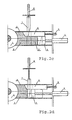
- Figs. 2a to 2d show an embodiment that is otherwise similar to that of Fig. 1 except that only one auxiliary piston 6 and one closing member 7 are used therein.
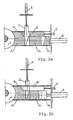
- Figs. 3a and 3b in tum, show the cross-sections of two different embodiments of the closing members and the corresponding shapes of the piston 5 and the auxiliary pistons 6, seen from the same direction.
- the closing member 7 is a single continuous sheet-like component, whereby the piston 5 comprises, at the edges, two press surfaces 5a pressing the wood and between the surfaces a recess 5b essentially corresponding in shape with the closing member 7.
- the auxiliary piston 6 comprises an elongated aperture 6a in the middle, the aperture being wider than the closing member 7 and its length in the longitudinal direction of the auxiliary piston 6 being such that the auxiliary piston can move a sufficient distance.
- the piston 5 comprises three press surfaces 5a pressing the wood and two recesses 5b between them, the shape of the recesses being such that the parallel closing members can push into the piston 5, between the piston and the wood.
- the auxiliary piston 6 comprises two apertures 6a, the distance between the apertures and the width of the apertures being such that the closing members can push through the apertures. The length of the apertures 6a is such that the auxiliary piston 6 can move a desired distance in relation to the closing members.
- the closing members are arranged on those sides of the feed chute 2 which are essentially parallel to the axle of the grindstone 1. Both the closing members 7 and those surfaces of the piston 5 which come into contact with the wood 3 are therefore crosswise of the axle of the grindstone 1, so that when the wood is parallel to the axle of the grindstone, as usual, the closing members 7 and those surfaces of the piston 5 which come into contact with the wood are also crosswise of the wood.
- the above description and the drawings present the invention only by way of example, without limiting it in any way.
- the closing members in the crosswise direction of the feed chute can either be continuous or consist of several parts, and the apertures of the auxiliary pistons and the recesses of the piston must be designed accordingly.
- the invention is not limited to a pulp grinder of a certain type. It can thus be used in both non-pressure grinders and pressure grinders, the other necessary operations and apparatuses being implemented conventionally in a previously known manner so that they are suited to the solutions in question.
Landscapes
- Engineering & Computer Science (AREA)
- Life Sciences & Earth Sciences (AREA)
- Wood Science & Technology (AREA)
- Mechanical Engineering (AREA)
- Debarking, Splitting, And Disintegration Of Timber (AREA)
- Paper (AREA)
- Crushing And Grinding (AREA)
- Disintegrating Or Milling (AREA)
- Filling Or Emptying Of Bunkers, Hoppers, And Tanks (AREA)
- Grinding Of Cylindrical And Plane Surfaces (AREA)
Claims (5)
- Aufbau zum Zuführen von Holz bei einem Holzstoffschleifer mitdadurch gekennzeichnet, dasseinem Schleifstein (1),einem Zuführschacht (2), der sich zu dem Schleifstein erstreckt,einem Kolben (5), der sich in dem Zuführschacht bewegt, um das Holz (3) gegen den Schleifstein (1) zu drücken, undzumindest ein Schließelement (7) zum Verhindern, dass das Holz sich von dem Schleifstein (1) wegbewegt, wenn der Kolben(5) von dem Schleifstein (1) wegbewegt wird, um so die Zufuhr einer neuen Charge an Holz zu ermöglichen,der Kolben (5) zumindest eine Vertiefung (5b) aufweist, in die das zumindest eine Schließelement (7) so gedrückt werden kann, dass, wenn das zumindest eine Schließelement in dem Zuführschacht (2) gedrückt wird, der Zuführschacht quer zu dem zu schleifenden Holz (3) geschlossen ist, so dass die rückwärtige Bewegung des Holzes (3) im wesentlichen verhindert ist, wenn sich der Kolben (5) zurückbewegt.
- Aufbau gemäß Anspruch 1,
dadurch gekennzeichnet, dasser zumindest einen Hilfskolben zum Drücken des Holzes gegen den Schleifstein aufweist,der Hilfskolben (6) zumindest eine Öffnung (6a) aufweist, so dass das zumindest eine Schließelement (7) durch den Hilfskolben (6) drücken kann, unddie Länge von jeder Öffnung (6a) des Hilfskolbens (6) in der Laufrichtung des Hilfskolbens (6) derart ist, dass, wenn das Schließelement (7) den Zuführschacht (2) schließt, der Hilfskolben (6) zu dem Schleifstein (1) hin bewegt werden kann, um das Holz kontinuierlich den Schleifstein zu drücken. - Aufbau gemäß Anspruch 2,
dadurch gekennzeichnet, dasser zumindest zwei Schließelemente (7) an entgegengesetzten Seiten des Zuführschachtes (2) aufweist, undan jeder Seite des Kolbens (5) ein Hilfskolben (6) vorhanden ist, undjeder Hilfskolben (6) zumindest eine Öffnung (6a) aufweist, durch die eines der Schließelemente (7) drücken kann, um den Zuführschacht (2) zu schließen. - Aufbau gemäß einem der Ansprüche 1 bis 3,
dadurch gekennzeichnet, dassjedes Schließelement (7) aus einem kontinuierlichen Schließelement besteht undder Kolben (5) eine einzelne Vertiefung (5b) quer zu dem Kolben der Laufrichtung der Schließelemente aufweist. - Aufbau gemäß einem der Ansprüche 1 bis 3,
dadurch gekennzeichnet, dasser zumindest zwei Schließelemente (7) in der Querrichtung des Zuführschachtes an beiden Seiten des Zuführschachtes aufweist undder Kolben (5) eine gleiche Anzahl an Vertiefungen (5b) wie die Anzahl an Schließelementen in der Querrichtung des Kolbens (5) aufweist.
Applications Claiming Priority (3)
| Application Number | Priority Date | Filing Date | Title |
|---|---|---|---|
| FI965047 | 1996-12-16 | ||
| FI965047A FI101895B1 (fi) | 1996-12-16 | 1996-12-16 | Sovitelma puiden syöttämiseksi puuhiomakoneessa |
| PCT/FI1997/000782 WO1998027267A1 (en) | 1996-12-16 | 1997-12-12 | Arrangement for feeding wood in a pulp grinder |
Publications (2)
| Publication Number | Publication Date |
|---|---|
| EP0944758A1 EP0944758A1 (de) | 1999-09-29 |
| EP0944758B1 true EP0944758B1 (de) | 2002-07-17 |
Family
ID=8547280
Family Applications (1)
| Application Number | Title | Priority Date | Filing Date |
|---|---|---|---|
| EP97947062A Expired - Lifetime EP0944758B1 (de) | 1996-12-16 | 1997-12-12 | Beschickungsvorrichtung in einem holzschleifer |
Country Status (10)
| Country | Link |
|---|---|
| US (1) | US6095443A (de) |
| EP (1) | EP0944758B1 (de) |
| JP (1) | JP2001506712A (de) |
| KR (1) | KR100519552B1 (de) |
| AT (1) | ATE220741T1 (de) |
| BR (1) | BR9713716A (de) |
| CA (1) | CA2274978A1 (de) |
| DE (1) | DE69714073T2 (de) |
| FI (1) | FI101895B1 (de) |
| WO (1) | WO1998027267A1 (de) |
Families Citing this family (1)
| Publication number | Priority date | Publication date | Assignee | Title |
|---|---|---|---|---|
| US7581484B1 (en) * | 2005-08-22 | 2009-09-01 | The United States Of America As Represented By The Secretary Of The Army | Weapon system retention device |
Family Cites Families (7)
| Publication number | Priority date | Publication date | Assignee | Title |
|---|---|---|---|---|
| FI11486A (fi) * | 1927-03-04 | Anordning för kontinuerlig matning av slipapparat | ||
| US1359016A (en) * | 1919-11-15 | 1920-11-16 | James H Baker | Pulp-wood grinder |
| DE413214C (de) * | 1923-08-11 | 1925-05-01 | Karlstads Mek Verkst Ab | Holzmagazin fuer Holzschleifer zur Erzeugung von Holzschliff fuer die Papier- und Pappenfabrikation |
| DE1975587U (de) * | 1967-05-19 | 1967-12-21 | Miag Muehlenbau & Ind Gmbh | Zweipressen-holzschleifer. |
| DE1811187A1 (de) * | 1968-11-27 | 1970-06-11 | Voith Gmbh J M | Zweipressenschleifer |
| DE2812299A1 (de) * | 1978-03-21 | 1979-09-27 | Voith Gmbh J M | Verfahren und vorrichtung zum herstellen von holzschliff |
| DE3636226A1 (de) * | 1986-10-24 | 1988-04-28 | Voith Gmbh J M | Holzschleifer |
-
1996
- 1996-12-16 FI FI965047A patent/FI101895B1/fi not_active IP Right Cessation
-
1997
- 1997-12-12 JP JP52736398A patent/JP2001506712A/ja active Pending
- 1997-12-12 BR BR9713716-2A patent/BR9713716A/pt not_active IP Right Cessation
- 1997-12-12 KR KR10-1999-7005245A patent/KR100519552B1/ko not_active Expired - Fee Related
- 1997-12-12 CA CA002274978A patent/CA2274978A1/en not_active Abandoned
- 1997-12-12 US US09/319,289 patent/US6095443A/en not_active Expired - Fee Related
- 1997-12-12 DE DE69714073T patent/DE69714073T2/de not_active Expired - Lifetime
- 1997-12-12 AT AT97947062T patent/ATE220741T1/de not_active IP Right Cessation
- 1997-12-12 EP EP97947062A patent/EP0944758B1/de not_active Expired - Lifetime
- 1997-12-12 WO PCT/FI1997/000782 patent/WO1998027267A1/en not_active Ceased
Also Published As
| Publication number | Publication date |
|---|---|
| US6095443A (en) | 2000-08-01 |
| ATE220741T1 (de) | 2002-08-15 |
| DE69714073D1 (de) | 2002-08-22 |
| CA2274978A1 (en) | 1998-06-25 |
| KR100519552B1 (ko) | 2005-10-13 |
| BR9713716A (pt) | 2000-01-25 |
| FI965047A0 (fi) | 1996-12-16 |
| EP0944758A1 (de) | 1999-09-29 |
| FI101895B (fi) | 1998-09-15 |
| KR20000057536A (ko) | 2000-09-25 |
| WO1998027267A1 (en) | 1998-06-25 |
| FI965047L (fi) | 1998-06-17 |
| FI101895B1 (fi) | 1998-09-15 |
| DE69714073T2 (de) | 2002-11-28 |
| JP2001506712A (ja) | 2001-05-22 |
Similar Documents
| Publication | Publication Date | Title |
|---|---|---|
| US4973001A (en) | Material bed roller mill | |
| EP0944758B1 (de) | Beschickungsvorrichtung in einem holzschleifer | |
| EP0944757B1 (de) | Vorrichtung zum fortlaufenden schleifen in einem holzschleifer | |
| EP0944759B1 (de) | Holzschleifer | |
| CS276955B6 (en) | Press for continuous manufacture of thin particle boards and fibreboards | |
| US5556043A (en) | Angled-rib blocking slab for pulpwood grinder | |
| US7033155B2 (en) | Hydraulic press for compressing metallic powder | |
| FI20002266A7 (fi) | Laite pellettien puristamiseksi | |
| EP0079336B1 (de) | Verfahren und schleifmühle zur herstellung von holzstoff | |
| EP0468458B1 (de) | Verfahren und Vorrichtung zum Auswechseln eines Messers in einem Disk-Zerspaner | |
| EP0583297B1 (de) | Verfahren und vorrichtung zur fein- und feinst- und mikrofeinzerkleinerung von sprödem mahlgut | |
| EP3045054B1 (de) | Fördereinrichtung zum zuführen eines verdichteten tabakkuchens zu einer tabakschneidevorrichtung | |
| JPS5933473Y2 (ja) | ジヨ−クラツシヤ用テンシヨンロツドスプリングの調整装置 | |
| JPS63283763A (ja) | ダブルトグルジヨ−クラツシヤ | |
| WO1994005439A1 (en) | Adjustable re-usable ceramic inserts | |
| FR2633197A1 (fr) | Procede de broyage fin de mineraux et broyeur a cylindres perfectionne pour la mise en oeuvre de ce procede | |
| JPH05285404A (ja) | ジョークラッシャーを高性能運転する方法 | |
| PL125099B1 (en) | Meat grinder | |
| DD234457B1 (de) | Vorrichtung zum verdichten von flocke und fasrigem material | |
| NZ199947A (en) | Manufacturing pulp from wood chips:wood chips compressed into body and fed to grinding zone having converging wall surfaces formed by grinder |
Legal Events
| Date | Code | Title | Description |
|---|---|---|---|
| PUAI | Public reference made under article 153(3) epc to a published international application that has entered the european phase |
Free format text: ORIGINAL CODE: 0009012 |
|
| 17P | Request for examination filed |
Effective date: 19990615 |
|
| AK | Designated contracting states |
Kind code of ref document: A1 Designated state(s): AT BE CH DE DK ES FI FR GB GR IE IT LI LU MC NL PT SE |
|
| RAP1 | Party data changed (applicant data changed or rights of an application transferred) |
Owner name: METSO PAPER, INC. |
|
| GRAG | Despatch of communication of intention to grant |
Free format text: ORIGINAL CODE: EPIDOS AGRA |
|
| 17Q | First examination report despatched |
Effective date: 20010918 |
|
| GRAG | Despatch of communication of intention to grant |
Free format text: ORIGINAL CODE: EPIDOS AGRA |
|
| GRAG | Despatch of communication of intention to grant |
Free format text: ORIGINAL CODE: EPIDOS AGRA |
|
| GRAH | Despatch of communication of intention to grant a patent |
Free format text: ORIGINAL CODE: EPIDOS IGRA |
|
| GRAH | Despatch of communication of intention to grant a patent |
Free format text: ORIGINAL CODE: EPIDOS IGRA |
|
| GRAA | (expected) grant |
Free format text: ORIGINAL CODE: 0009210 |
|
| AK | Designated contracting states |
Kind code of ref document: B1 Designated state(s): AT BE CH DE DK ES FI FR GB GR IE IT LI LU MC NL PT SE |
|
| PG25 | Lapsed in a contracting state [announced via postgrant information from national office to epo] |
Ref country code: NL Free format text: LAPSE BECAUSE OF FAILURE TO SUBMIT A TRANSLATION OF THE DESCRIPTION OR TO PAY THE FEE WITHIN THE PRESCRIBED TIME-LIMIT Effective date: 20020717 Ref country code: LI Free format text: LAPSE BECAUSE OF FAILURE TO SUBMIT A TRANSLATION OF THE DESCRIPTION OR TO PAY THE FEE WITHIN THE PRESCRIBED TIME-LIMIT Effective date: 20020717 Ref country code: IT Free format text: LAPSE BECAUSE OF FAILURE TO SUBMIT A TRANSLATION OF THE DESCRIPTION OR TO PAY THE FEE WITHIN THE PRESCRIBED TIME-LIMIT;WARNING: LAPSES OF ITALIAN PATENTS WITH EFFECTIVE DATE BEFORE 2007 MAY HAVE OCCURRED AT ANY TIME BEFORE 2007. THE CORRECT EFFECTIVE DATE MAY BE DIFFERENT FROM THE ONE RECORDED. Effective date: 20020717 Ref country code: GR Free format text: LAPSE BECAUSE OF FAILURE TO SUBMIT A TRANSLATION OF THE DESCRIPTION OR TO PAY THE FEE WITHIN THE PRESCRIBED TIME-LIMIT Effective date: 20020717 Ref country code: FR Free format text: LAPSE BECAUSE OF FAILURE TO SUBMIT A TRANSLATION OF THE DESCRIPTION OR TO PAY THE FEE WITHIN THE PRESCRIBED TIME-LIMIT Effective date: 20020717 Ref country code: FI Free format text: LAPSE BECAUSE OF FAILURE TO SUBMIT A TRANSLATION OF THE DESCRIPTION OR TO PAY THE FEE WITHIN THE PRESCRIBED TIME-LIMIT Effective date: 20020717 Ref country code: CH Free format text: LAPSE BECAUSE OF FAILURE TO SUBMIT A TRANSLATION OF THE DESCRIPTION OR TO PAY THE FEE WITHIN THE PRESCRIBED TIME-LIMIT Effective date: 20020717 Ref country code: BE Free format text: LAPSE BECAUSE OF FAILURE TO SUBMIT A TRANSLATION OF THE DESCRIPTION OR TO PAY THE FEE WITHIN THE PRESCRIBED TIME-LIMIT Effective date: 20020717 |
|
| REF | Corresponds to: |
Ref document number: 220741 Country of ref document: AT Date of ref document: 20020815 Kind code of ref document: T |
|
| REG | Reference to a national code |
Ref country code: GB Ref legal event code: FG4D |
|
| REG | Reference to a national code |
Ref country code: CH Ref legal event code: EP |
|
| REG | Reference to a national code |
Ref country code: IE Ref legal event code: FG4D |
|
| REF | Corresponds to: |
Ref document number: 69714073 Country of ref document: DE Date of ref document: 20020822 |
|
| PG25 | Lapsed in a contracting state [announced via postgrant information from national office to epo] |
Ref country code: PT Free format text: LAPSE BECAUSE OF FAILURE TO SUBMIT A TRANSLATION OF THE DESCRIPTION OR TO PAY THE FEE WITHIN THE PRESCRIBED TIME-LIMIT Effective date: 20021017 Ref country code: DK Free format text: LAPSE BECAUSE OF FAILURE TO SUBMIT A TRANSLATION OF THE DESCRIPTION OR TO PAY THE FEE WITHIN THE PRESCRIBED TIME-LIMIT Effective date: 20021017 |
|
| NLV1 | Nl: lapsed or annulled due to failure to fulfill the requirements of art. 29p and 29m of the patents act | ||
| PG25 | Lapsed in a contracting state [announced via postgrant information from national office to epo] |
Ref country code: LU Free format text: LAPSE BECAUSE OF NON-PAYMENT OF DUE FEES Effective date: 20021212 Ref country code: IE Free format text: LAPSE BECAUSE OF NON-PAYMENT OF DUE FEES Effective date: 20021212 Ref country code: GB Free format text: LAPSE BECAUSE OF NON-PAYMENT OF DUE FEES Effective date: 20021212 |
|
| PG25 | Lapsed in a contracting state [announced via postgrant information from national office to epo] |
Ref country code: ES Free format text: LAPSE BECAUSE OF FAILURE TO SUBMIT A TRANSLATION OF THE DESCRIPTION OR TO PAY THE FEE WITHIN THE PRESCRIBED TIME-LIMIT Effective date: 20030130 |
|
| REG | Reference to a national code |
Ref country code: CH Ref legal event code: PL |
|
| EN | Fr: translation not filed | ||
| PLBE | No opposition filed within time limit |
Free format text: ORIGINAL CODE: 0009261 |
|
| STAA | Information on the status of an ep patent application or granted ep patent |
Free format text: STATUS: NO OPPOSITION FILED WITHIN TIME LIMIT |
|
| PG25 | Lapsed in a contracting state [announced via postgrant information from national office to epo] |
Ref country code: MC Free format text: LAPSE BECAUSE OF NON-PAYMENT OF DUE FEES Effective date: 20030701 |
|
| 26N | No opposition filed |
Effective date: 20030422 |
|
| GBPC | Gb: european patent ceased through non-payment of renewal fee | ||
| REG | Reference to a national code |
Ref country code: IE Ref legal event code: MM4A |
|
| PGFP | Annual fee paid to national office [announced via postgrant information from national office to epo] |
Ref country code: AT Payment date: 20081215 Year of fee payment: 12 |
|
| PGFP | Annual fee paid to national office [announced via postgrant information from national office to epo] |
Ref country code: SE Payment date: 20081212 Year of fee payment: 12 |
|
| EUG | Se: european patent has lapsed | ||
| PG25 | Lapsed in a contracting state [announced via postgrant information from national office to epo] |
Ref country code: AT Free format text: LAPSE BECAUSE OF NON-PAYMENT OF DUE FEES Effective date: 20091212 |
|
| PG25 | Lapsed in a contracting state [announced via postgrant information from national office to epo] |
Ref country code: SE Free format text: LAPSE BECAUSE OF NON-PAYMENT OF DUE FEES Effective date: 20091213 |
|
| PGFP | Annual fee paid to national office [announced via postgrant information from national office to epo] |
Ref country code: DE Payment date: 20111222 Year of fee payment: 15 |
|
| REG | Reference to a national code |
Ref country code: DE Ref legal event code: R119 Ref document number: 69714073 Country of ref document: DE Effective date: 20130702 |
|
| PG25 | Lapsed in a contracting state [announced via postgrant information from national office to epo] |
Ref country code: DE Free format text: LAPSE BECAUSE OF NON-PAYMENT OF DUE FEES Effective date: 20130702 |