EP0944757B1 - Vorrichtung zum fortlaufenden schleifen in einem holzschleifer - Google Patents
Vorrichtung zum fortlaufenden schleifen in einem holzschleifer Download PDFInfo
- Publication number
- EP0944757B1 EP0944757B1 EP97947061A EP97947061A EP0944757B1 EP 0944757 B1 EP0944757 B1 EP 0944757B1 EP 97947061 A EP97947061 A EP 97947061A EP 97947061 A EP97947061 A EP 97947061A EP 0944757 B1 EP0944757 B1 EP 0944757B1
- Authority
- EP
- European Patent Office
- Prior art keywords
- wood
- feed chute
- grindstone
- piston
- feed
- Prior art date
- Legal status (The legal status is an assumption and is not a legal conclusion. Google has not performed a legal analysis and makes no representation as to the accuracy of the status listed.)
- Expired - Lifetime
Links
- 239000002023 wood Substances 0.000 claims abstract description 84
- 238000003825 pressing Methods 0.000 claims abstract description 9
- 230000006835 compression Effects 0.000 description 10
- 238000007906 compression Methods 0.000 description 10
- 230000000694 effects Effects 0.000 description 1
- 238000004519 manufacturing process Methods 0.000 description 1
- 238000000034 method Methods 0.000 description 1
- 238000005507 spraying Methods 0.000 description 1
- 239000000725 suspension Substances 0.000 description 1
- XLYOFNOQVPJJNP-UHFFFAOYSA-N water Substances O XLYOFNOQVPJJNP-UHFFFAOYSA-N 0.000 description 1
Images


Classifications
-
- D—TEXTILES; PAPER
- D21—PAPER-MAKING; PRODUCTION OF CELLULOSE
- D21B—FIBROUS RAW MATERIALS OR THEIR MECHANICAL TREATMENT
- D21B1/00—Fibrous raw materials or their mechanical treatment
- D21B1/04—Fibrous raw materials or their mechanical treatment by dividing raw materials into small particles, e.g. fibres
- D21B1/12—Fibrous raw materials or their mechanical treatment by dividing raw materials into small particles, e.g. fibres by wet methods, by the use of steam
- D21B1/14—Disintegrating in mills
- D21B1/18—Disintegrating in mills in magazine-type machines
-
- D—TEXTILES; PAPER
- D21—PAPER-MAKING; PRODUCTION OF CELLULOSE
- D21B—FIBROUS RAW MATERIALS OR THEIR MECHANICAL TREATMENT
- D21B1/00—Fibrous raw materials or their mechanical treatment
- D21B1/04—Fibrous raw materials or their mechanical treatment by dividing raw materials into small particles, e.g. fibres
- D21B1/12—Fibrous raw materials or their mechanical treatment by dividing raw materials into small particles, e.g. fibres by wet methods, by the use of steam
- D21B1/14—Disintegrating in mills
- D21B1/26—Driving or feeding arrangements
Definitions
- the invention relates to an arrangement for providing continuous grinding in a pulp grinder comprising a grindstone, a feed chute extending to the grindstone, a piston for pressing the wood in the feed chute against the grindstone, and a closing member that can be moved crosswise of the feed chute to prevent the wood from moving backward from the grindstone when the piston is moved away from the grindstone.
- the grinders typically used are grinders in which the blocks of wood are pressed against the surface of a rotary grindstone, simultaneously spraying water there to produce a pulp suspension.
- the most generally, the wood supply is implemented in pulp grinders on a discontinuous basis: one batch of wood at a time is fed into a feed chute, after which the wood in the feed chute is pressed by a cylinder against the grindstone.
- two feed chutes, with cylinders are usually arranged on the opposite sides of the grindstone. Consequently, when a feed chute is being filled, the grindstone is subjected to less load than when both the feed chutes are in the grinding step, and this causes both uneven loading and variation in the quality of the ground pulp.
- the drawback of the discontinuous supply is that the output is smaller when the wood is fed in batches than when continuous grinding is used.
- Another problem in the discontinuous grinding is that the blocks of wood fed during the compression press more firmly against each other, which also results in variation between the production rates at the beginning and at the end of the grinding. Consequently, for example the freeness of the ground pulp is higher at the beginning of the compression, dropping toward the end of the furnace, even if the feed rate at the piston of the cylinder is adjusted to remain constant. For the same reason, the motor is loaded unevenly, and the loading increases toward the end of the compression.
- EP-A-0 266 582 discloses an arrangement according to the preamble of claim 1.
- the capacity of the grinder is naturally smaller than in solutions where wood from two or more feed chutes can be ground simultaneously.
- Another problem in the high feed chutes is that the blocks of wood may settle obliquely, which affects the grindstone and because of which the grinder must be sharpened unduly often in order to correct the obliqueness. Since the pressing force of the chains does not divide evenly between the blocks of wood in the feed chute, but in practice the blocks of wood that are the closest to the chains are fed at a higher feed rate than those in the middle of the feed chute, this affects the quality and may also cause the above obliqueness.
- the object of the invention is to provide an arrangement avoiding the drawbacks of the above embodiments and providing continuous and even wood supply to the grindstone.
- the arrangement of the invention is characterized by comprising rotary feed members between the piston and the grindstone on the opposite sides of the feed chute, the feed members pushing the wood in the feed chute toward the grindstone, and the piston comprising at least one recess, into which, behind the wood, the closing member can push as the piston presses the wood.
- the invention in addition to the cylinder and the piston connected thereto the invention comprises separate rotary feed members, which feed the batch of wood already compressed by the cylinder and the piston against the grindstone when the piston is moved away from the pressing position in order to feed a new batch of wood into the feed chute.
- the invention comprises a separate closing member that can be inserted behind the batch of wood compressed by the piston onto the side of the piston so that the batch of wood will not be able to move back from the compression when the piston is moved back in order to feed a new batch of wood.
- the advantage of the invention is that the batch of wood is pressed by the piston, whereby the compressed batch of wood is easy to press further against the grindstone by rotary transfer members at that end of the feed chute which is close to the grindstone.
- Another advantage of the invention is that when the backward movement of the batch of wood has been prevented by the closing member, the piston can be moved to the initial position and a new batch of wood can be fed and subsequently pressed to compress it. The grinding conditions on the surface of the grindstone are thus maintained essentially constant, irrespective of the current state of compression of the last-fed batch of wood. Further, the wood can be fed so that the grinding is continuous although the wood is added in batches.
- the entire feed chute can be designed relatively short as compared with the known solutions, and that more than one feed chute can be arranged to extend to one and the same grindstone, since the weight of the wood will not essentially affect the wood feed characteristics and thereby the quality of the ground pulp.
- Fig. 1 is a schematic view of a part of a grinder comprising a grindstone 1.
- a feed chute 2 along which wood 3 is supplied against the grindstone 1 in a manner known per se.
- a feed cylinder 4 comprising a piston 5 that pushes the wood against the grindstone 1.
- the wood is supplied in front of the piston 5 in batches 3', the batches being then pushed by the piston against the wood 3 that has been supplied to the feed chute 2 earlier.
- rotary feed members 6, which in this embodiment consist of chains 6b running around return wheels 6a. As the chains 6b run around, they push the wood 3 toward the grindstone 1.
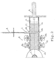
- FIG. 2 shows a closing member 7 that can be moved by a closing cylinder 8 through apertures 2a in the walls of the feed chute 2 to behind the wood in the feed chute, between the piston 5 and the wood 3.
- a closing member 7 that can be moved by a closing cylinder 8 through apertures 2a in the walls of the feed chute 2 to behind the wood in the feed chute, between the piston 5 and the wood 3.
- Fig. 2 is a schematic view of an embodiment that is otherwise similar to that of Fig. 1 except that the rotary feed members 6 are here gears provided with long teeth 6c extending to the feed chute 2, the teeth transferring the wood 3 that is between the closing member 7 and the grindstone 1 toward the grindstone 1 as the gears rotate.
- the rotary feed members 6 are here gears provided with long teeth 6c extending to the feed chute 2, the teeth transferring the wood 3 that is between the closing member 7 and the grindstone 1 toward the grindstone 1 as the gears rotate.
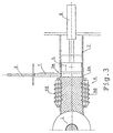
- Fig. 3 in turn shows an embodiment that is otherwise similar to that of Fig. 1 except that the rotary feed members 6 are here coarse-teeth screws rotating about axles in the longitudinal direction of the feed chute 2 and thereby transferring the wood 3 on their screw surface 6d toward the grindstone 1.
- the rotary feed members are located on those sides of the feed chute 2 which are parallel to the axle of the grindstone 1. This results from the fact that the wood 3 in the feed chute 2 is also parallel to the axle of the grindstone 1, whereby the wood is easier to supply evenly.
- the closing member 7 is arranged to move crosswise of the feed chute 2 between the sides, i.e. crosswise of the axle of the grindstone 1, whereby the closing member 7 is behind the wood 3 crosswise thereof, and the surfaces of piston that are in contact with wood are also crosswise thereof.
- Figs. 4a and 4b are schematic views showing different ways of arranging the closing member 7 and the piston 5 in relation to each other so that they can co-operate easily.
- Fig. 4a shows a potential shape of the piston 5 seen from the direction of the closing member 7.
- the piston 5 comprises two parts 5a pressing the wood, and a recess 5 between them.
- the cross-section of the closing member 7, in turn, is such that the closing member fits the recess 5 between the wood 3 and the piston 5.
- Fig. 4b shows another embodiment in which the piston 5 comprises three parts 5a pressing the wood, and two recesses 5b between the parts.
- the closing members 7 comprise two parts that can be moved crosswise of the feed chute 2 and that fit the recesses 5b. This embodiment allows the wood 3 to be pressed more evenly, which may be useful.
- the invention comprises a compression cylinder with a piston by which the wood can be pressed against the grindstone.
- the invention comprises rotary feed members by which the wood compressed by the piston in the feed chute can be pressed further against the grindstone when the piston is moved away from the pressing position so as to allow a new batch of wood to be fed.
- the invention comprises a closing member preventing the compressed wood from moving backward after the compression when the piston is moved away from the pressing position.
- the arrangement of the invention can be applied in many different ways.
- the feed chutes can be arranged horizontally, vertically or obliquely, since the direction does not have an essential effect on their operation. Continuous grinding is thereby achieved, in which the grinding situation and therefore the operating conditions and characteristics of the grinder stay essentially constant and in which the ground pulp obtained is of more even quality and the loading of the motor of the grinder is also more even.
- the invention is not limited to a pulp grinder of a certain type. It can thus be used in both non-pressure grinders and pressure grinders, the other necessary operations and apparatuses being implemented conventionally in a previously known manner so that they suit the solutions in question.
Landscapes
- Engineering & Computer Science (AREA)
- Life Sciences & Earth Sciences (AREA)
- Wood Science & Technology (AREA)
- Mechanical Engineering (AREA)
- Debarking, Splitting, And Disintegration Of Timber (AREA)
- Crushing And Grinding (AREA)
- Paper (AREA)
- Polishing Bodies And Polishing Tools (AREA)
- Grinding Of Cylindrical And Plane Surfaces (AREA)
- Finish Polishing, Edge Sharpening, And Grinding By Specific Grinding Devices (AREA)
Claims (8)
- Aufbau zum Vorsehen eines kontinuierlichen Schleifens bei einem Holzstoffschleifer mit einem Schleifstein (1), einem Zufuhrschacht (2), der sich zu dem Schleifstein erstreckt, einem Kolben (5) für ein Drücken des Holzes in dem Zuführschacht gegen den Schleifstein (1) und einem beweglichen Schließelement (7) quer zu dem Zuführschacht (2), um zu verhindern, dass sich das Holz (3) von dem Schleifstein (1) zurückbewegt, wenn der Kolben (5) von dem Schleifstein (1) weg bewegt ist,
dadurch gekennzeichnet, dass
er Drehzuführelemente (6) zwischen dem Kolben (5) und dem Schleifstein an den entgegengesetzten Seiten des Zuführschachtes (2) aufweist, wobei die Zuführelemente das Holz (3) in dem Zuführschacht (2) zu dem Schleifstein (1) hin drücken, und der Kolben (5) zumindest eine Vertiefung (5b) aufweist, in die hinter dem Holz (3) das Schließelement (7) drücken kann, wenn der Kolben (5) das Holz (3) drückt. - Aufbau gemäß Anspruch 1,
dadurch gekennzeichnet, dass
die Drehzuführelemente (6) Ketten (6b) aufweisen, die um Umkehrräder (6) an entgegengesetzten Seiten des Zuführschachtes laufen. - Aufbau gemäß Anspruch 1,
dadurch gekennzeichnet, dass
die Drehzuführelemente Zahnräder (6), die mit Zähnen (6c) versehen sind, die sich zu dem Zuführschacht (2) erstrecken, an entgegengesetzten Seiten des Zuführschachtes (2) aufweisen. - Aufbau gemäß Anspruch 1,
dadurch gekennzeichnet, dass
die Drehzuführelemente (6) Schrauben aufweisen, die mit Grobschraubflächen (6d) an den entgegengesetzten Seiten des Zuführschachtes (2) vorgesehen sind, wobei die Schraubenflächen (6d) sich zu dem Holz (3) in dem Zuführschacht (2) erstrecken. - Aufbau gemäß einem der vorherigen Ansprüche,
dadurch gekennzeichnet, dass
zumindest zwei Drehzuführelemente (6) quer zu dem Zuführschacht (2) an beiden Seiten des Zuführschachtes vorhanden sind. - Aufbau gemäß einem der vorherigen Ansprüche,
dadurch gekennzeichnet, dass
die Drehzuführelemente (6) an jenen Seiten des Zuführschachtes (2) angeordnet sind, die parallel zu der Achse des Schleifsteins (1) sind, und dass das Schließelement derart eingerichtet ist, dass es sich in Bezug auf den Zuführschacht (2) quer zu der Achse des Schleifsteins (1) bewegt. - Aufbau gemäß einem der vorherigen Ansprüche,
dadurch gekennzeichnet, dass
das Schließelement ein einstückiges Schließelement ist und der Kolben (5) eine Vertiefung (5b) aufweist, die im Wesentlichen in der Mitte ist, um das Schließelement (7) aufzunehmen. - Aufbau gemäß einem der Ansprüche 1 bis 4,
dadurch gekennzeichnet, dass
das Schließeelement zumindest zwei separate Abschnitte aufweist, die quer zu dem Zuführschacht (2) gedrückt werden können, und dass der Kolben (5) in entsprechender Weise zwei Vertiefungen (5b) zum Aufnehmen der zwei Abschnitte des Schließelementes (7) aufweist.
Applications Claiming Priority (3)
| Application Number | Priority Date | Filing Date | Title |
|---|---|---|---|
| FI965046A FI101894B (fi) | 1996-12-16 | 1996-12-16 | Sovitelma jatkuvatoimisen hionnan aikaansaamiseksi puuhiomakoneessa |
| FI965046 | 1996-12-16 | ||
| PCT/FI1997/000781 WO1998027266A1 (en) | 1996-12-16 | 1997-12-12 | Arrangement for providing continuous grinding in a pulp grinder |
Publications (2)
| Publication Number | Publication Date |
|---|---|
| EP0944757A1 EP0944757A1 (de) | 1999-09-29 |
| EP0944757B1 true EP0944757B1 (de) | 2002-06-05 |
Family
ID=8547279
Family Applications (1)
| Application Number | Title | Priority Date | Filing Date |
|---|---|---|---|
| EP97947061A Expired - Lifetime EP0944757B1 (de) | 1996-12-16 | 1997-12-12 | Vorrichtung zum fortlaufenden schleifen in einem holzschleifer |
Country Status (10)
| Country | Link |
|---|---|
| US (1) | US6109550A (de) |
| EP (1) | EP0944757B1 (de) |
| JP (1) | JP2001506711A (de) |
| KR (1) | KR20000057529A (de) |
| AT (1) | ATE218641T1 (de) |
| BR (1) | BR9713715A (de) |
| CA (1) | CA2275637A1 (de) |
| DE (1) | DE69713140T2 (de) |
| FI (1) | FI101894B (de) |
| WO (1) | WO1998027266A1 (de) |
Families Citing this family (2)
| Publication number | Priority date | Publication date | Assignee | Title |
|---|---|---|---|---|
| US7581484B1 (en) * | 2005-08-22 | 2009-09-01 | The United States Of America As Represented By The Secretary Of The Army | Weapon system retention device |
| CN102080339B (zh) * | 2010-10-18 | 2012-02-22 | 杭州珂瑞特机械制造有限公司 | 用于卫生产品生产线的双路进料装置及进料方法 |
Family Cites Families (9)
| Publication number | Priority date | Publication date | Assignee | Title |
|---|---|---|---|---|
| US1518583A (en) * | 1923-07-30 | 1924-12-09 | Port Arthur Shipbuilding Co Lt | Continuous-screw-feed magazine |
| DE413214C (de) * | 1923-08-11 | 1925-05-01 | Karlstads Mek Verkst Ab | Holzmagazin fuer Holzschleifer zur Erzeugung von Holzschliff fuer die Papier- und Pappenfabrikation |
| US1644148A (en) * | 1924-08-16 | 1927-10-04 | Priem Paul | Apparatus for feeding continuous working wood grinders |
| US1652044A (en) * | 1925-02-04 | 1927-12-06 | Nenzel Georg | Apparatus for feeding mechanical grinding machines for producing wood pulp |
| US2297438A (en) * | 1938-12-01 | 1942-09-29 | Stehr Robert | Wood pulp grinder |
| DE2812299A1 (de) * | 1978-03-21 | 1979-09-27 | Voith Gmbh J M | Verfahren und vorrichtung zum herstellen von holzschliff |
| FI60251C (fi) * | 1979-07-20 | 1981-12-10 | Tampella Oy Ab | Taetningsanordning foer en tillslutningslucka foer ett tryckslipverk |
| FI67103C (fi) * | 1983-03-22 | 1985-01-10 | Tampella Oy Ab | Spaerrskiva foer en vedslipmaskin |
| DE3636226A1 (de) * | 1986-10-24 | 1988-04-28 | Voith Gmbh J M | Holzschleifer |
-
1996
- 1996-12-16 FI FI965046A patent/FI101894B/fi active
-
1997
- 1997-12-12 US US09/319,287 patent/US6109550A/en not_active Expired - Fee Related
- 1997-12-12 JP JP52736298A patent/JP2001506711A/ja active Pending
- 1997-12-12 AT AT97947061T patent/ATE218641T1/de not_active IP Right Cessation
- 1997-12-12 KR KR1019990705237A patent/KR20000057529A/ko not_active Withdrawn
- 1997-12-12 DE DE69713140T patent/DE69713140T2/de not_active Expired - Fee Related
- 1997-12-12 EP EP97947061A patent/EP0944757B1/de not_active Expired - Lifetime
- 1997-12-12 CA CA002275637A patent/CA2275637A1/en not_active Abandoned
- 1997-12-12 WO PCT/FI1997/000781 patent/WO1998027266A1/en not_active Ceased
- 1997-12-12 BR BR9713715-4A patent/BR9713715A/pt not_active IP Right Cessation
Also Published As
| Publication number | Publication date |
|---|---|
| FI101894B1 (fi) | 1998-09-15 |
| FI965046A7 (fi) | 1998-06-17 |
| DE69713140T2 (de) | 2002-11-07 |
| JP2001506711A (ja) | 2001-05-22 |
| BR9713715A (pt) | 2000-01-25 |
| EP0944757A1 (de) | 1999-09-29 |
| FI965046A0 (fi) | 1996-12-16 |
| US6109550A (en) | 2000-08-29 |
| KR20000057529A (ko) | 2000-09-25 |
| DE69713140D1 (de) | 2002-07-11 |
| WO1998027266A1 (en) | 1998-06-25 |
| FI101894B (fi) | 1998-09-15 |
| ATE218641T1 (de) | 2002-06-15 |
| CA2275637A1 (en) | 1998-06-25 |
Similar Documents
| Publication | Publication Date | Title |
|---|---|---|
| US4905910A (en) | Double roll machine such as, for example, a roll press | |
| US4838494A (en) | Roller mill, particularly roll press or roll jaw crusher | |
| EP0328647A1 (de) | Walzenbrecher und brechverfahren mit anwendung desselben | |
| EP2464457A1 (de) | Verfahren und vorrichtung zur feinmahlung von mineralischen materialien | |
| EP0944757B1 (de) | Vorrichtung zum fortlaufenden schleifen in einem holzschleifer | |
| TW363885B (en) | Grain milling machine | |
| EP0944758B1 (de) | Beschickungsvorrichtung in einem holzschleifer | |
| EP0399192A1 (de) | Walzenpresse insbesondere zur Druckzerkleinerung körnigen Gutes | |
| EP0687503A1 (de) | Walzenzerkleinerer | |
| CS276955B6 (en) | Press for continuous manufacture of thin particle boards and fibreboards | |
| EP0944759B1 (de) | Holzschleifer | |
| DE3228517A1 (de) | Verdichtungssystem zum zusammenpressen und verdichten von pulverisierten abfallstoffen in brennstoffwuerfel | |
| EP0079336B1 (de) | Verfahren und schleifmühle zur herstellung von holzstoff | |
| EP0583297B1 (de) | Verfahren und vorrichtung zur fein- und feinst- und mikrofeinzerkleinerung von sprödem mahlgut | |
| RU2036725C1 (ru) | Валковый пресс для измельчения и разупрочнения минерального сырья | |
| EP3045054B1 (de) | Fördereinrichtung zum zuführen eines verdichteten tabakkuchens zu einer tabakschneidevorrichtung | |
| JPS63283763A (ja) | ダブルトグルジヨ−クラツシヤ | |
| WO2001041990A1 (en) | Spreader | |
| JPH044026B2 (de) |
Legal Events
| Date | Code | Title | Description |
|---|---|---|---|
| PUAI | Public reference made under article 153(3) epc to a published international application that has entered the european phase |
Free format text: ORIGINAL CODE: 0009012 |
|
| 17P | Request for examination filed |
Effective date: 19990615 |
|
| AK | Designated contracting states |
Kind code of ref document: A1 Designated state(s): AT BE CH DE DK ES FI FR GB GR IE IT LI LU MC NL PT SE |
|
| GRAG | Despatch of communication of intention to grant |
Free format text: ORIGINAL CODE: EPIDOS AGRA |
|
| RAP1 | Party data changed (applicant data changed or rights of an application transferred) |
Owner name: METSO PAPER, INC. |
|
| 17Q | First examination report despatched |
Effective date: 20010808 |
|
| GRAG | Despatch of communication of intention to grant |
Free format text: ORIGINAL CODE: EPIDOS AGRA |
|
| GRAH | Despatch of communication of intention to grant a patent |
Free format text: ORIGINAL CODE: EPIDOS IGRA |
|
| GRAH | Despatch of communication of intention to grant a patent |
Free format text: ORIGINAL CODE: EPIDOS IGRA |
|
| GRAA | (expected) grant |
Free format text: ORIGINAL CODE: 0009210 |
|
| AK | Designated contracting states |
Kind code of ref document: B1 Designated state(s): AT BE CH DE DK ES FI FR GB GR IE IT LI LU MC NL PT SE |
|
| PG25 | Lapsed in a contracting state [announced via postgrant information from national office to epo] |
Ref country code: NL Free format text: LAPSE BECAUSE OF FAILURE TO SUBMIT A TRANSLATION OF THE DESCRIPTION OR TO PAY THE FEE WITHIN THE PRESCRIBED TIME-LIMIT Effective date: 20020605 Ref country code: LI Free format text: LAPSE BECAUSE OF FAILURE TO SUBMIT A TRANSLATION OF THE DESCRIPTION OR TO PAY THE FEE WITHIN THE PRESCRIBED TIME-LIMIT Effective date: 20020605 Ref country code: IT Free format text: LAPSE BECAUSE OF FAILURE TO SUBMIT A TRANSLATION OF THE DESCRIPTION OR TO PAY THE FEE WITHIN THE PRESCRIBED TIME-LIMIT;WARNING: LAPSES OF ITALIAN PATENTS WITH EFFECTIVE DATE BEFORE 2007 MAY HAVE OCCURRED AT ANY TIME BEFORE 2007. THE CORRECT EFFECTIVE DATE MAY BE DIFFERENT FROM THE ONE RECORDED. Effective date: 20020605 Ref country code: GR Free format text: LAPSE BECAUSE OF FAILURE TO SUBMIT A TRANSLATION OF THE DESCRIPTION OR TO PAY THE FEE WITHIN THE PRESCRIBED TIME-LIMIT Effective date: 20020605 Ref country code: FR Free format text: LAPSE BECAUSE OF FAILURE TO SUBMIT A TRANSLATION OF THE DESCRIPTION OR TO PAY THE FEE WITHIN THE PRESCRIBED TIME-LIMIT Effective date: 20020605 Ref country code: FI Free format text: LAPSE BECAUSE OF FAILURE TO SUBMIT A TRANSLATION OF THE DESCRIPTION OR TO PAY THE FEE WITHIN THE PRESCRIBED TIME-LIMIT Effective date: 20020605 Ref country code: CH Free format text: LAPSE BECAUSE OF FAILURE TO SUBMIT A TRANSLATION OF THE DESCRIPTION OR TO PAY THE FEE WITHIN THE PRESCRIBED TIME-LIMIT Effective date: 20020605 Ref country code: BE Free format text: LAPSE BECAUSE OF FAILURE TO SUBMIT A TRANSLATION OF THE DESCRIPTION OR TO PAY THE FEE WITHIN THE PRESCRIBED TIME-LIMIT Effective date: 20020605 |
|
| REF | Corresponds to: |
Ref document number: 218641 Country of ref document: AT Date of ref document: 20020615 Kind code of ref document: T |
|
| REG | Reference to a national code |
Ref country code: GB Ref legal event code: FG4D |
|
| REG | Reference to a national code |
Ref country code: CH Ref legal event code: EP |
|
| REG | Reference to a national code |
Ref country code: IE Ref legal event code: FG4D |
|
| REF | Corresponds to: |
Ref document number: 69713140 Country of ref document: DE Date of ref document: 20020711 |
|
| PG25 | Lapsed in a contracting state [announced via postgrant information from national office to epo] |
Ref country code: PT Free format text: LAPSE BECAUSE OF FAILURE TO SUBMIT A TRANSLATION OF THE DESCRIPTION OR TO PAY THE FEE WITHIN THE PRESCRIBED TIME-LIMIT Effective date: 20020905 Ref country code: DK Free format text: LAPSE BECAUSE OF FAILURE TO SUBMIT A TRANSLATION OF THE DESCRIPTION OR TO PAY THE FEE WITHIN THE PRESCRIBED TIME-LIMIT Effective date: 20020905 |
|
| NLV1 | Nl: lapsed or annulled due to failure to fulfill the requirements of art. 29p and 29m of the patents act | ||
| PG25 | Lapsed in a contracting state [announced via postgrant information from national office to epo] |
Ref country code: LU Free format text: LAPSE BECAUSE OF NON-PAYMENT OF DUE FEES Effective date: 20021212 Ref country code: IE Free format text: LAPSE BECAUSE OF NON-PAYMENT OF DUE FEES Effective date: 20021212 Ref country code: GB Free format text: LAPSE BECAUSE OF NON-PAYMENT OF DUE FEES Effective date: 20021212 |
|
| REG | Reference to a national code |
Ref country code: CH Ref legal event code: PL |
|
| PG25 | Lapsed in a contracting state [announced via postgrant information from national office to epo] |
Ref country code: ES Free format text: LAPSE BECAUSE OF FAILURE TO SUBMIT A TRANSLATION OF THE DESCRIPTION OR TO PAY THE FEE WITHIN THE PRESCRIBED TIME-LIMIT Effective date: 20021220 |
|
| EN | Fr: translation not filed | ||
| PLBE | No opposition filed within time limit |
Free format text: ORIGINAL CODE: 0009261 |
|
| STAA | Information on the status of an ep patent application or granted ep patent |
Free format text: STATUS: NO OPPOSITION FILED WITHIN TIME LIMIT |
|
| 26N | No opposition filed |
Effective date: 20030306 |
|
| PG25 | Lapsed in a contracting state [announced via postgrant information from national office to epo] |
Ref country code: MC Free format text: LAPSE BECAUSE OF NON-PAYMENT OF DUE FEES Effective date: 20030701 |
|
| GBPC | Gb: european patent ceased through non-payment of renewal fee | ||
| REG | Reference to a national code |
Ref country code: IE Ref legal event code: MM4A |
|
| PGFP | Annual fee paid to national office [announced via postgrant information from national office to epo] |
Ref country code: SE Payment date: 20061213 Year of fee payment: 10 Ref country code: AT Payment date: 20061213 Year of fee payment: 10 |
|
| PGFP | Annual fee paid to national office [announced via postgrant information from national office to epo] |
Ref country code: DE Payment date: 20061218 Year of fee payment: 10 |
|
| EUG | Se: european patent has lapsed | ||
| PG25 | Lapsed in a contracting state [announced via postgrant information from national office to epo] |
Ref country code: AT Free format text: LAPSE BECAUSE OF NON-PAYMENT OF DUE FEES Effective date: 20071212 |
|
| PG25 | Lapsed in a contracting state [announced via postgrant information from national office to epo] |
Ref country code: SE Free format text: LAPSE BECAUSE OF NON-PAYMENT OF DUE FEES Effective date: 20071213 Ref country code: DE Free format text: LAPSE BECAUSE OF NON-PAYMENT OF DUE FEES Effective date: 20080701 |