EP0944544B1 - Procede et dispositif pour transporter des produits maintenus individuellement - Google Patents
Procede et dispositif pour transporter des produits maintenus individuellement Download PDFInfo
- Publication number
- EP0944544B1 EP0944544B1 EP97913069A EP97913069A EP0944544B1 EP 0944544 B1 EP0944544 B1 EP 0944544B1 EP 97913069 A EP97913069 A EP 97913069A EP 97913069 A EP97913069 A EP 97913069A EP 0944544 B1 EP0944544 B1 EP 0944544B1
- Authority
- EP
- European Patent Office
- Prior art keywords
- conveying
- elements
- holding
- products
- paths
- Prior art date
- Legal status (The legal status is an assumption and is not a legal conclusion. Google has not performed a legal analysis and makes no representation as to the accuracy of the status listed.)
- Expired - Lifetime
Links
- 238000000034 method Methods 0.000 title claims description 50
- 230000008878 coupling Effects 0.000 claims abstract description 123
- 238000010168 coupling process Methods 0.000 claims abstract description 123
- 238000005859 coupling reaction Methods 0.000 claims abstract description 123
- 210000001520 comb Anatomy 0.000 claims description 7
- 238000005096 rolling process Methods 0.000 claims description 2
- 230000003213 activating effect Effects 0.000 claims 1
- 239000000047 product Substances 0.000 description 53
- 230000008569 process Effects 0.000 description 8
- 238000003032 molecular docking Methods 0.000 description 4
- 230000001360 synchronised effect Effects 0.000 description 4
- 230000004913 activation Effects 0.000 description 3
- 230000008901 benefit Effects 0.000 description 3
- 230000009849 deactivation Effects 0.000 description 3
- 230000005484 gravity Effects 0.000 description 3
- 235000004522 Pentaglottis sempervirens Nutrition 0.000 description 1
- 230000009286 beneficial effect Effects 0.000 description 1
- 238000005516 engineering process Methods 0.000 description 1
- 239000013067 intermediate product Substances 0.000 description 1
- 239000000696 magnetic material Substances 0.000 description 1
- 238000004519 manufacturing process Methods 0.000 description 1
- 238000007639 printing Methods 0.000 description 1
Images


Classifications
-
- B—PERFORMING OPERATIONS; TRANSPORTING
- B65—CONVEYING; PACKING; STORING; HANDLING THIN OR FILAMENTARY MATERIAL
- B65H—HANDLING THIN OR FILAMENTARY MATERIAL, e.g. SHEETS, WEBS, CABLES
- B65H29/00—Delivering or advancing articles from machines; Advancing articles to or into piles
- B65H29/58—Article switches or diverters
- B65H29/60—Article switches or diverters diverting the stream into alternative paths
-
- B—PERFORMING OPERATIONS; TRANSPORTING
- B65—CONVEYING; PACKING; STORING; HANDLING THIN OR FILAMENTARY MATERIAL
- B65H—HANDLING THIN OR FILAMENTARY MATERIAL, e.g. SHEETS, WEBS, CABLES
- B65H29/00—Delivering or advancing articles from machines; Advancing articles to or into piles
- B65H29/003—Delivering or advancing articles from machines; Advancing articles to or into piles by grippers
-
- B—PERFORMING OPERATIONS; TRANSPORTING
- B65—CONVEYING; PACKING; STORING; HANDLING THIN OR FILAMENTARY MATERIAL
- B65H—HANDLING THIN OR FILAMENTARY MATERIAL, e.g. SHEETS, WEBS, CABLES
- B65H2301/00—Handling processes for sheets or webs
- B65H2301/30—Orientation, displacement, position of the handled material
- B65H2301/32—Orientation of handled material
- B65H2301/323—Hanging
-
- B—PERFORMING OPERATIONS; TRANSPORTING
- B65—CONVEYING; PACKING; STORING; HANDLING THIN OR FILAMENTARY MATERIAL
- B65H—HANDLING THIN OR FILAMENTARY MATERIAL, e.g. SHEETS, WEBS, CABLES
- B65H2301/00—Handling processes for sheets or webs
- B65H2301/40—Type of handling process
- B65H2301/44—Moving, forwarding, guiding material
- B65H2301/447—Moving, forwarding, guiding material transferring material between transport devices
- B65H2301/4471—Grippers, e.g. moved in paths enclosing an area
-
- B—PERFORMING OPERATIONS; TRANSPORTING
- B65—CONVEYING; PACKING; STORING; HANDLING THIN OR FILAMENTARY MATERIAL
- B65H—HANDLING THIN OR FILAMENTARY MATERIAL, e.g. SHEETS, WEBS, CABLES
- B65H2405/00—Parts for holding the handled material
- B65H2405/50—Gripping means
- B65H2405/56—Gripping means releasably connected to transporting means
Definitions
- the invention is in the field of conveyor technology and relates to a method for conveying individually kept products according to the generic term of the first independent claim, and an arrangement for Implementation of the procedure according to the generic term of the corresponding independent claim.
- the products to be considered below are kept individually if necessary, individual paths essentially continuously through a Funded network of conveyor lines.
- the products brought to stations from a manufacturing process for example which they are processed individually, or they are processed by a processing station to another processing station or through processing stations, in which they worked during the continuous funding will be supported.
- An example of products to be handled in this way are Print products that start from the printing press through various Processing stations are processed and made ready for dispatch.
- Conveyor systems which run independently of one another have holding means which can be moved by conveyor lines, that is to say not together connected holding means. Such arrangements are particularly suitable for funding procedures with product-specific funding channels, whereby for Guiding the movement of the holding device guide systems with product-specific controllable branching and merging points provided become.
- Such conveyor systems can be operated very flexibly, but are in Regarding control and drive means rather complex. For repatriation the holding means must also have correspondingly controllable guide systems be provided.
- the invention now has as its object a method for the promotion of individual products to demonstrate the benefits of those described above Systems combined, but largely eliminates their disadvantages.
- the method should be largely independent of shape variations Regarding the products to be promoted, it should also be for very high Funding services are applicable and it is said to be better than known ones Procedures in various areas through which to promote the products are adaptable to a wide variety of funding tasks. It is also the task the invention, an arrangement for performing the method create which arrangement simply for various local funding tasks is customizable and easily expandable.
- the method according to the invention is based on each product to be conveyed assign a holding element, which holding element the product in holds a defined way and which holding element together covers the entire transport route predetermined for the product with the product, which conveyor path consists of a series of conveyor lines.
- the Holding elements are coupled for conveying to parts that run along a specific conveyor line are movable, or on guides that are extend along a specific conveyor line.
- the holding elements each have at least one a first coupling part, with the help of which they on second coupling parts can be coupled, with every second coupling part essentially assigned to a specific conveyor path and movable along this.
- the holding elements can also be used Help the first coupling parts also on guides that run along a Extend conveyor line, be coupled.
- a product to be funded by held a holding element and the holding element is by means of the first Coupling part to a second coupling part movable along the conveyor line or to a guide extending along the conveyor line coupled, the coupling part or a conveyor element on which it is arranged is, or the holding element is driven by suitable means.
- transfer areas that is, at places where the product is from a conveyor line is directed to another conveyor line
- the holding element from the second coupling part which can be moved on the one conveyor line or decoupled from the corresponding guide and to one on the other Conveyor path movable second coupling part or to a corresponding Leadership coupled, this handing over all products of a stream can affect or only individual.
- the advantage of the method is on the one hand that the products to be promoted need to be gripped only once, reducing the risk of damage is significantly reduced, making the process largely independent will depend on the exact shape of the products.
- they can on conveyor lines movable second coupling parts depending on the conveying task specific conveyor section of an envisaged network of conveyor sections in of very different types.
- the second coupling parts can For example, be arranged on conveyor chains in an equidistant manner. If holding elements are coupled to such a conveyor chain they function as a well-known conveyor chain, as described at the beginning has been.
- the second coupling parts can also be on links of chains can be arranged with variable link spacing or they can be at completely conveyor elements movable independently of one another.
- Appropriate drive means must also be designed and arrange.
- conveyor lines with movable second coupling parts can also conveyor lines in an arrangement according to the invention be provided on which the holding elements can be moved without coupling are, for example, that their first coupling parts in corresponding configured guides slide, for example driven by gravity.
- Such additional conveyor lines are particularly suitable for non-continuous funding, for example for buffer routes and for return routes.
- Another advantage of the inventive method and the inventive Arrangement is that in processes where it is beneficial is to identify the products individually, the means of identification are not be arranged on the products themselves but on the holding elements and therefore cannot leave the conveyor system with the products, but circulate in the system with the holding elements.
- Such means for Identification is, for example, writable and readable without contact electronic units.
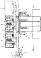
- FIG. 1 schematically shows a first exemplary variant of the method according to the invention using a very limited network with only two conveyor sections A and B in a transfer area U and its immediate surroundings.
- the two conveyor lines are shown schematically by lines with an arrow (conveying direction).
- Second coupling parts 2, which are shown schematically as white squares, can be moved on the two conveyor lines.
- first coupling parts 1 are shown schematically as black circles.
- a first coupling part 1 is arranged on a holding element (not shown), which holding element holds a product 3.
- the product (seen from the back in FIG. 1) is, for example, a printed product, that is to say a newspaper, a magazine or a brochure or an intermediate product for one of the products mentioned.
- FIG. 1 can be understood, for example, as a bird's eye view are, i.e. the conveyor sections A and B, coupling parts 1 and 2 and the holding elements are arranged above the suspended products 3.
- the representation can just as well be understood as a side view, that is, the products 3 are held laterally, the conveyor section A comes from above and the conveyor line B goes down. Mixed forms too are easily imaginable.
- the second coupling parts 2 are constant Distances from one another, for example in an articulated manner Chain links arranged moved.
- the conveyor line A have the second Coupling parts 2 no constant distances from each other, that is, they are for example on loosely connected conveyor elements or arranged on individual conveyor elements. For this reason, are for to provide the transfer area U synchronization means (not shown), with the help of the second coupling parts 2 on the conveyor section A at least in the transfer area U with the second coupling parts 2 on the conveyor line B synchronized, or clocked into the transfer area.
- the chain drives are correspondingly equidistant from another chain to synchronize.
- the holding elements with the first coupling parts 1 are on the feed side (left in the figure) to the transfer area U to the on the conveyor line A movable second coupling parts 2 coupled.
- each first coupling part 1 is replaced by the corresponding second coupling part 2 decoupled from conveyor section A, moved transversely to the conveying direction (arrow Q) and coupled to a second coupling part 2 of the conveyor section B.
- On the conveying side (in the figure on the right) from the transfer area U are the Holding elements or first coupling parts 1 on second coupling parts 2 the conveyor line B coupled and are further promoted on this.
- the second coupling parts 2 of the two conveyor sections A and B means to provide through which the movement of the holding elements or the first Coupling parts 1 are moved transversely to the conveying direction (arrow Q), for example corresponding movement backdrops, as shown by the dash-dotted lines Lines a and b are indicated.
- arrow Q conveying direction
- the funds for the transverse movement must be corresponding be designed to be controllable. In appropriate arrangements can be used as a means gravity can also be used for transverse movement.
- Locking means are also advantageously provided, with the help of which two coupled coupling parts 1 and 2 locked together become.
- Appropriate control means must also be provided in the transfer area U.
- FIGS. 2 and 3 show an exemplary embodiment of a holding element 4 with a first coupling part 1 and a conveying element 5, which can be moved in a guide 6 (defined conveying path) and on which a second coupling part 2 is arranged.
- Holding element 4 and conveying element 5 are shown in FIG. 2 with a viewing direction transverse to the conveying direction, in FIG. 3 with a viewing direction parallel to the conveying direction.
- Holding elements 4 and conveying elements 5 equipped according to FIGS. 2 and 3 can be used in a method variant according to FIG. 1.
- Coupling parts (1/2) consists of one part with one facing outwards narrowing groove 11 and from a comb 12 with a narrowed neck area 13, groove 11 and comb 12 coordinated cross sections have and at least in a takeover area essentially across
- the conveying direction is such that the comb 12 is transverse to the conveying direction can be pushed out of the groove 11.
- the holding element 4 has, for example, a gripper 41 with which a Print product 3 is gripped and held.
- grippers are general known, for example by the publication CH-569197 or US-3948551 (F62).
- the conveying element 5 has, for example, two groups of three Balls 51, with the help of which it is in a corresponding guide channel 61 is rolling movable.
- Such conveying elements 5 are in the publication EP-0387318 and US-5074678.
- two guide channels 61 are parallel to each other out and the conveyor elements 5 are synchronized such that always a pair of conveyor elements with combs aligned 12 are promoted through the transfer area.
- the distance between the guide channels 61 is selected in the transfer area such that the distance between two moving synchronously through the transfer area Combing 12 of two synchronously moving conveyor elements 5 is less than the length of a groove 11 of a holding element 4.
- Conveying element 5 can be pushed onto the comb 12 of the other conveying element 5, these means all holding element conveyed through the transfer area can push or can be controlled such that they are only specific push the holding device.
- These means are, for example, movement backdrops or magnet systems, which are particularly controllable Suitable means.
- FIG. 4 shows a further embodiment of holding elements 4 and conveying elements 5, which are coupled to one another by a pair of coupling parts (1 and 2) (view parallel to the conveying direction) as a representation of a further transfer area through which three conveyor sections A, B and C lead.
- the holding element 4 in turn has a gripper 41 which holds a product 3 and which can be activated or deactivated by means of control rollers 42 for gripping a product or releasing it.
- the conveying element 5 is a link in a link chain which can be moved on rollers 52 in a guide channel 61.
- a groove 11 is arranged as the second coupling part 2 (coupling parts reversed compared to the embodiment according to Figures 2 and 3). How from the detail view F can be seen transversely to the conveying direction, there is the groove 11 from a tube segment and the head part of the comb 12 from a tube, whose outside diameter corresponds to the inside diameter of the pipe segment is coordinated.
- the holding element 4 also has control rollers 43 which are used to push the Comb 12 from the groove 11 of a conveying element 5 into the groove of another Conveyor element on correspondingly arranged backdrops (not shown) unroll.
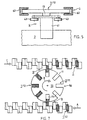
- FIG. 5 shows how a holding element 4 can be moved along an additional conveyor section G, which additional conveyor section has no second coupling parts.
- the holding element 4 essentially corresponds to the holding element of FIG. 4 and is equipped with control rollers 43 and with a comb 12 as the first coupling part 1.
- the comb 12 which is used for coupling to a second coupling part has a neck region 13 which extends only over a central part of the comb length, so that the lateral regions of the comb 12 are free pipe ends.
- the holding element 4 can slide on both sides in corresponding, for example U-shaped guide rails 62, which can represent a further conveying variant for a specific area (for example a buffer section) of an inventive conveying arrangement.
- a return path for empty holding elements can also be realized in such a manner, the holding elements advantageously being driven by gravity or by other, for example, pushing drive means.
- FIG. 6 schematically shows a further transfer area U with two conveyor sections A and B.
- this transfer area there are again holding elements, of which only the first coupling parts are shown in the form of combs, in corresponding grooves 11 of conveyor elements 5.1 of the conveyor section A in grooves 11 of Conveying elements 5.2 of the conveying path B are displaceable, the grooves 11 and combs 12 running essentially transversely to the conveying direction at least in the transfer area U.
- the conveyor elements 5.1 which are movable on the conveyor section A, are closed linked together in a chain so that their distances are invariable are.
- the conveying elements 5.2 are free, that is to say they are not connected to one another Elements.
- the funding elements 5.1 and 5.2 are for an automatic Synchronization designed.
- the chain of conveying elements 5.1 points to this between the conveyor elements concave docking points 53, in the convex Docking points 54 of the conveyor elements 5.2 fit.
- the free funding elements 5.2 are now guided against the chain of conveyor elements 5.1 in such a way that one convex docking point 54 each of a free conveying element 5.2 in one concave docking point 53 between two connected conveying elements 5.1 in a kind of form fit is docked.
- FIG. 7 shows, as a further example of an arrangement for carrying out the method variant according to FIG. 1, part of a network of conveyor lines. Parts of three conveyor sections A, B and C are shown and two transfer areas U.
- the conveyor elements of conveyor sections A and C correspond to the conveyor elements as described in connection with FIG. 6.
- the conveying elements of the conveying section C are cells 56 arranged on a rotating wheel 55, which have, for example, a groove 11 as second coupling parts 2, into which first coupling parts 1, for example combs 12, can be inserted.
- FIG. 8 shows a further variant of a transfer area which is operated essentially according to the same method variant as the transfer area of FIG. 1.
- two conveyor sections A and B are shown on which second coupling parts 2 (white squares) can be moved.
- a plurality of transverse conveyor elements 7 are arranged between the two conveyor sections A and B, and can be moved along a third conveyor section D in synchronization with the conveyor elements of the conveyor sections A and B.
- the holding elements (only first coupling parts 1 shown as black circles) with the products 3 are each transferred to a transverse conveyor element 7 by decoupling the first coupling part 1 of the holding element from the coupling part 2 of the conveyor section A and onto the transverse conveyor element 7 is pushed.
- the transverse conveying element 7 differs from the conveying element in that instead of a second coupling part 2 it has a guide on which the first coupling part 1 of the holding element can be displaced essentially transversely to the general conveying direction.
- Control link shown schematically by the dash-dotted line a
- control backdrop also the two transfers U.1 and U.2 can control.
- transverse conveyor elements 7 for the cross-conveying of the holding elements with appropriate drive means are equipped.
- the promotion of holding devices and products in the transverse conveyor elements 7, as shown in FIG be continuous or a standstill can also be provided.
- FIG. 9 shows the same transfer area as FIG. 8 as a three-dimensional representation. Only first coupling parts 1, second coupling parts 2 of the conveying sections A and B and a transverse guide 71 of a transverse conveying element are shown.
- the coupling parts 1 and 2 correspond to the coupling parts shown in Figures 2 and 3.
- the transverse guide 71 of the transverse conveyor element is essentially a comb 12 with a narrowed neck region 13 with the same cross section as the comb 12 of the second coupling part 2, but is usually longer than this.
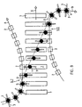
- FIG. 10 schematically shows an application of the transfer area with transverse conveying, as has already been described in connection with FIGS. 8 and 9.
- the transverse conveying elements 7 are axially extending compartments 72 of a processing drum 73.
- the product-conveying conveying path A, the drum 73 and the conveying-away conveying path B are staggered one behind the other perpendicular to the paper plane of FIG. 10, such that the transverse conveying essentially is perpendicular to the plane of the paper and the first transfer U.1 is carried out in a front axial region of the drum 73, the second transfer U.2 is carried out in a rear axial part of the drum.
- the products 3 are held by grippers 41 by means of first coupling parts 1 coupled to the second coupling parts 2 fed along the conveyor section A.
- first coupling parts 1 become the second coupling parts 2 decouples and the products including holding elements (gripper 41 and first Coupling part 1) pushed into a compartment 72 of the drum 73, or each first coupling part 1 is on a transverse guide 71, the bottom of each Compartment 72 is provided.
- the holding elements continue, for example, along the transverse guides 71 moved in the axial direction of the drum 73 and the products 3 conveyed, for example, by a processing station 74 and processed therein.
- second handover U.2 on the other Front of the drum 73 the processed products held by the grippers 41 by means of the first coupling parts 1 on second coupling parts Conveyor line B coupled and conveyed away.
- FIG. 11 shows a further exemplary variant of the method according to the invention on the basis of a transfer area U through which two conveyor lines A and B are guided.
- This method variant differs from the method variant according to FIGS. 1 and 8 in that the holding elements 4 each have at least two first coupling parts 1, wherein they are coupled to a second coupling part for conveyance with one of the first coupling parts.
- the transverse movement Q of the holding elements 4 when transferring is unnecessary with such a method variant.
- FIG. 12 shows a viewing area parallel to the conveying direction, in which, according to the second method variant (FIG. 11), holding elements 4 with products 3 can be transferred from a conveying section A to a conveying section B (or vice versa).
- Control means are to be provided in the transfer area with which the clutch grippers 15 can be activated or deactivated.
- the skilled worker is a gripper and control means for their activation or deactivation known from conveyor systems according to the state of the art, with which grippers products be grasped and held.
- Such grippers are for a function as adapt the second coupling parts 2 (clutch gripper) accordingly.
- first coupling parts 1 and second coupling parts 2 in the process variant according to FIG Known coupling parts are used in a transfer area are controllable accordingly.
- FIG. 13 shows a further variant of first and second coupling parts for the method variant according to FIG. 11.
- a transfer area with two conveying sections A and B is shown (viewing direction parallel to the conveying direction), which conveying sections each define by a guide 63 extending along the conveying section are.
- the first coupling parts 1 of the holding elements 4 are as runners which can be coupled to the guide rail and slide or roll on it.
- the guide 63 thus not only defines the conveying section but is at the same time a second coupling part 2 for each holding element 4 to be conveyed along the conveying section, a different area of the guide serving as a second coupling part at each location of the conveying section and the coupling thereby being movable along the conveying section .
- Each holding element 4 has two first coupling parts 1 in the form of the Guide 63 connectable runners 16.
- Runner 16 from two rotor parts 16.1 and 16.2, with suitable control means and if necessary with resetting means in a closed around the guide 63 State and can be brought into an open state.
- the runners 16 roll, for example, as shown on rollers 20 on the guide 63 or they slide on it.
- Embodiments are also conceivable in which the guide 63 simultaneously Is driving means, i.e. is moved along the conveyor line, and the first coupling parts 1 not designed as a rotor but as clamping parts are, with the help of the holding elements 4 can be clamped to the guide.
- FIG. 14 again shows a third variant of the method according to the invention on the basis of a representation of a transfer area.
- Two conveyor sections A and B with guide channels 61 are shown very schematically, conveyor elements 5 being movable in the guide channels 61, as shown in more detail in FIG. 4.
- Second coupling parts 2 are arranged on the conveying elements and have an opening 17 oriented transversely to the conveying direction.
- the holding element 4 has a continuous same opening 17.
- the first coupling part 1 is a bolt 18 which has a cross section which is matched to the openings 17 and which can be displaced transversely to the conveying direction (arrow Q) in these openings.
- the holding element is coupled to a conveying element 5 which can be moved on the conveying path A or to a conveying element 5 which is movable on the conveying path B.
- openings 17 could also run accordingly, against each other outside narrowing grooves are provided.
- a drive means for the transverse movement Q of the pin 18 in this Case consists at least partially of a magnetic material, can for example correspondingly controllable electromagnets 19 for use come.
- the process variant according to FIG. 14, in which a direction transverse to the conveying direction sliding first coupling part is used is a variant which lies between the variants according to FIGS. 1 and 11.
- the holding element 4 only has a first coupling part 1 or bolt 18 on (variant Figure 1), but becomes the holding element 4 during the transfer not shifted transversely to the conveying direction (variant Figure 11).
Claims (23)
- Procédé destiné au transport d'un grand nombre de produits (3) au moins similaires dans un réseau de voies de transport (A, B, C), les produits (3) étant retenus individuellement pendant le transport, caractérisé en ce que chacun des produits (3) est transporté en étant retenu par un élément de retenue (4), les éléments de retenue (4) étant couplés à des éléments de transport (5) pouvant être déplacés le long d'une voie de transport (A, B, C), ou à des guidages (63) s'étendant le long d'une voie de transport (A, B, C), et en ce que, pour le transfert des produits (3) d'une voie de transport (A) sur une autre voie de transport (B), les éléments de retenue (4) sont découplés des éléments de transport (5) ou des guidages (63) de l'une des voies de transport (A) et couplés aux éléments de transport ou aux guidages de l'autre voie de transport (B).
- Procédé selon la revendication 1, caractérisé en ce que des éléments de retenue (4) transportés le long d'une voie de transport (A) dans une zone de transfert (U), tous ou certains spécifiques sont transférés sur l'autre voie de transport (B).
- Procédé selon la revendication 1 ou 2, caractérisé en ce que les éléments de retenue (4) retenant les produits (3) sont couplés pour le transport des produits (3) à des éléments de transport (5) pouvant être déplacés le long d'une voie de transport (A, B), et en ce que dans une zone de transfert (U), les éléments de transport (5) de deux voies de transport (A, B) sont déplacés parallèlement et de façon synchrone, et les éléments de retenue (4) d'un élément de transport (5) d'une voie de transport (A) sont déplacés pour l'essentiel transversalement à la direction de transport sur un élément de transport (5) de l'autre voie de transport (B).
- Procédé selon la revendication 1 ou 2, caractérisé en ce que les éléments de retenue (4) retenant les produits (3) sont couplés pour le transport le long d'une voie de transport (A, B) à des éléments de transport (5) pouvant être déplacés le long de cette voie de transport, en ce que dans une zone de transfert ils sont déplacés, lors d'un premier transfert (U.1), des éléments de transport (5) d'une première voie de transport (A) sur des éléments de transport transversaux (7) se déplaçant parallèlement et de façon synchrone avec les éléments de transport (5), et en ce que lors d'un deuxième transfert (U.2), ils sont déplacés sur des éléments de transport (5) se déplaçant parallèlement et de façon synchrone avec les éléments de transport transversaux (7) d'une deuxième voie de transport (B).
- Procédé selon la revendication 4, caractérisé en ce que, dans les éléments de transport transversaux (7), les éléments de retenue (4) retenant les produits sont pour l'essentiel déplacés et/ou traités transversalement aux directions de transport des première et deuxième voies de transport (A, B).
- Procédé selon la revendication 1 ou 2, caractérisé en ce que les éléments de retenue (4) retenant les produits (3) sont couplés pour le transport des produits (3) à des éléments de transport (5) pouvant être déplacés le long d'une voie de transport (A, B), et en ce que dans une zone de transfert (U), les éléments de transport (5) d'une première et d'une deuxième voie de transport (A, B) sont déplacés parallèlement et de façon synchrone, et en ce que les éléments de retenue (4) couplés à un élément de transport (5) de la première voie de transport (A) sont déplacés dans la zone de transfert (U), sont ensuite couplés à un élément de transport (5) de la deuxième voie de transport (B), et sont ensuite découplés de l'élément de transport (5) de la première voie de transport (A).
- Procédé selon la revendication 1 ou 2, caractérisé en ce que les éléments de retenue (4) retenant les produits (3) sont couplés pour le transport des produits (3) à des guidages (63) s'étendant le long d'une voie de transport (A, B), en ce que dans une zone de transfert (U), les guidages (63) d'une première et d'une deuxième voie de transport (A, B) s'étendent parallèlement, et en ce que les éléments de retenue (4) couplés au guidage (63) de la première voie de transport (A) sont déplacés dans la zone de transfert (U), sont ensuite couplés au guidage (63) de la deuxième voie de transport (B), et sont ensuite découplés du guidage (63) de la première voie de transport (A).
- Procédé selon la revendication 1 ou 2, caractérisé en ce que les éléments de retenue (4) retenant les produits (3) sont couplés pour le transport des produits (3) à des éléments de transport (5) pouvant être déplacés le long d'une voie de transport (A, B), et en ce que dans une zone de transfert (U), les éléments de transport (5) de deux voies de transport (A, B) sont déplacés parallèlement et de façon synchrone, et en ce que pour le couplage et le découplage consécutif de l'élément de retenue (4), un élément d'accouplement (18) assurant le couplage de l'élément de retenue (4) à un élément de transport (5) est déplacé transversalement à la direction de transport d'un élément de transport (5) de la voie de transport (A) sur un élément de transport (5) de l'autre voie de transport (B).
- Procédé selon l'une quelconque des revendications 1 à 8, caractérisé en ce que les éléments de retenue (4) retenant les produits (3) sont déplacés sur des voies de transport supplémentaires (G), et glissent en l'occurrence dans des guidages (62) correspondants.
- Procédé selon l'une quelconque des revendications 1 à 9, caractérisé en ce que les éléments de retenue (4) retenant les produits (3) sont transportés à des écartements constants ou variables sur les voies de transport (A, B, C).
- Dispositif destiné à la mise en oeuvre du procédé selon la revendication 1, lequel dispositif comporte un réseau de voies de transport définies (A, B, C), et des moyens de retenue pouvant être déplacés le long des voies de transport afin de transporter les produits (3) à l'état retenu le long des voies de transport, caractérisé en ce que le réseau de voies de transport comporte des éléments de transport (5) pouvant être déplacés le long des voies de transport (A, B, C) ou des guidages (63) s'étendant le long des voies de transport (A, B, C), en ce que le réseau de voies de transport comporte en outre des zones de transfert (U) dans lesquelles au moins deux voies de transport (A, B, C) s'étendent parallèlement, et en ce que les moyens de retenue pouvant être déplacés le long des voies de transport (A, B, C) sont constitués d'éléments de retenue (4) pouvant être couplés à des éléments de transport (5) ou à des guidages (63), des moyens de commande (a, b, 43, 19) étant prévus dans les zones de transfert (U) pour le découplage d'éléments de retenue (4) d'éléments de transport (5) ou de guidages (63) d'une première voie de transport (A), et pour le couplage des éléments de retenue (4) à des éléments de transport (5) ou à des guidages (63) d'une deuxième voie de transport (B).
- Dispositif selon la revendication 11, caractérisé en ce que les éléments de retenue (4) comportent au moins un premier élément d'accouplement (1), et en ce que les éléments de transport pouvant être déplacés le long de voies de transport (A, B, C) comportent un d'un deuxième élément d'accouplement (1, 2) un élément de retenue (4) peut être couplé à un élément de transport (5), et en ce que des moyens de commande (a, b, 43) sont prévus dans des zones de transfert (U) pour le couplage ou le découplage de premiers et de deuxièmes éléments d'accouplement (1, 2).
- Dispositif selon la revendication 12, caractérisé en ce que le premier et le deuxième élément d'accouplement (1, 2) sont une cannelure (11) pouvant être orientée dans une zone de transfert (U) transversalement à la direction de transport, se rétrécissant vers l'extérieur, et un collet (12) avec une zone de gorge rétrécie (13) pouvant être orienté en direction de la cannelure (11), et en ce que des moyens de commande (a, b, 43) sont prévus dans des zones de transfert (U), avec lesquels des cannelures et des collets disposés sur des éléments de retenue (4) peuvent être déplacés pour l'essentiel transversalement à la direction de transport.
- Dispositif selon la revendication 12, caractérisé en ce que des éléments de transport transversaux (7) sont prévus dans des zones de transfert entre des voies de transport (A, B), qui peuvent être déplacés parallèlement aux voies de transport (A, B), au moins pour un premier et un deuxième transfert (U.1, U.2), et qui comportent des guidages transversaux (71) destinés au guidage des éléments de retenue (4) pour l'essentiel transversalement à la direction de transport, et en ce qu'il est prévu des moyens de commande avec lesquels des cannelures (11) ou des collets (12) disposés sur les éléments de retenue (4) peuvent, lors d'un premier transfert (U.1), être insérés par glissement dans les guidages transversaux (71) d'éléments de transport transversaux (7), et lors d'un deuxième transfert (U.2), extraits par glissement de guidages transversaux (71) d'éléments de transport transversaux (7).
- Dispositif selon la revendication 12, caractérisé en ce que les éléments de retenue (4) comportent au moins deux premiers éléments d'accouplement (1), et en ce que des moyens de commande sont prévus dans des zones de transfert (U) pour le découplage de l'un des premiers éléments d'accouplement (1) d'un deuxième élément d'accouplement (2) d'un élément de transport (5) d'une première voie de transport (A), et pour le couplage de l'autre premier élément d'accouplement (1) à un deuxième élément d'accouplement (2) d'un élément de transport (5) d'une deuxième voie de transport (B).
- Dispositif selon la revendication 15, caractérisé en ce que le premier élément d'accouplement (1) est un tube (14), et le deuxième élément d'accouplement (2) un grappin d'accouplement (15).
- Dispositif selon la revendication 12, caractérisé en ce que les premiers éléments d'accouplement (1) des éléments de retenue (4) peuvent être déplacés par rapport aux éléments de retenue (4), et en ce que des moyens de commande (19) sont prévus dans des zones de transfert (U) pour le déplacement des premiers éléments d'accouplement (1).
- Dispositif selon la revendication 17, caractérisé en ce que le premier élément d'accouplement (1) est une goupille (18) pouvant être déplacée dans un orifice (17) correspondant de l'élément de retenue (4), et en ce que le deuxième élément d'accouplement (2) comporte un orifice (17) correspondant ou une cannelure.
- Dispositif selon l'une quelconque des revendications 12 à 18, caractérisé en ce que les éléments de transport (5) sont des maillons de chaíne reliés entre eux par articulation à des écartements identiques invariables, en ce que les éléments de transport (5) sont des maillons de chaíne reliés entre eux de façon flexible à des écartements variables, et/ou en ce que les éléments de transport (5) ne sont pas reliés entre eux et peuvent être déplacés individuellement le long de voies de transport.
- Dispositif selon l'une quelconque des revendications 12 à 19, caractérisé en ce que les éléments de transport (5) sont au moins une partie des cellules (56) des voies de transport d'une roue cellulaire (55).
- Dispositif selon l'une quelconque des revendications 12 à 20, caractérisé en ce qu'il est prévu des voies de transport supplémentaires (G) le long desquelles s'étendent des guidages (62), dans lesquels des éléments de retenue (4) peuvent se déplacer en glissant ou en roulant.
- Dispositif selon la revendication 11, caractérisé en ce que les éléments de retenue (4) comportent au moins deux premiers éléments d'accouplement (1) avec lesquels ils peuvent être couplés à des guidages (63) s'étendant le long de voies de transport (A, B, C), et en ce que des moyens de commande sont prévus dans des zones de transfert (U) pour l'activation de l'un et pour la désactivation de l'autre des deux premiers éléments d'accouplement (1) au moins.
- Dispositif selon la revendication 22, caractérisé en ce que les premiers éléments d'accouplement (1) sont des curseurs (16) en deux parties, les deux parties de curseur (16.1 et 16.2) pouvant enserrer le guidage (63).
Priority Applications (1)
| Application Number | Priority Date | Filing Date | Title |
|---|---|---|---|
| DK97913069T DK0944544T4 (da) | 1996-12-13 | 1997-11-26 | Fremgangsmåde og anordning til transport af individuelt holdte produkter |
Applications Claiming Priority (3)
| Application Number | Priority Date | Filing Date | Title |
|---|---|---|---|
| CH306996 | 1996-12-13 | ||
| CH306996 | 1996-12-13 | ||
| PCT/CH1997/000444 WO1998025845A1 (fr) | 1996-12-13 | 1997-11-26 | Procede et dispositif pour transporter des produits maintenus individuellement |
Publications (3)
| Publication Number | Publication Date |
|---|---|
| EP0944544A1 EP0944544A1 (fr) | 1999-09-29 |
| EP0944544B1 true EP0944544B1 (fr) | 2001-10-24 |
| EP0944544B2 EP0944544B2 (fr) | 2005-03-16 |
Family
ID=4247940
Family Applications (1)
| Application Number | Title | Priority Date | Filing Date |
|---|---|---|---|
| EP97913069A Expired - Lifetime EP0944544B2 (fr) | 1996-12-13 | 1997-11-26 | Procede et dispositif pour transporter des produits maintenus individuellement |
Country Status (13)
| Country | Link |
|---|---|
| US (2) | US6302262B1 (fr) |
| EP (1) | EP0944544B2 (fr) |
| JP (1) | JP4030071B2 (fr) |
| CN (1) | CN1093832C (fr) |
| AT (1) | ATE207446T1 (fr) |
| AU (1) | AU740456B2 (fr) |
| BR (1) | BR9713578A (fr) |
| CA (1) | CA2274808C (fr) |
| DE (1) | DE59705111D1 (fr) |
| ES (1) | ES2167724T5 (fr) |
| NO (1) | NO312952B1 (fr) |
| RU (1) | RU2188150C2 (fr) |
| WO (1) | WO1998025845A1 (fr) |
Cited By (1)
| Publication number | Priority date | Publication date | Assignee | Title |
|---|---|---|---|---|
| WO2013029192A1 (fr) | 2011-08-30 | 2013-03-07 | Ferag Ag | Procédé, installation et unité de transport destinés à fournir des groupes de produits |
Families Citing this family (14)
| Publication number | Priority date | Publication date | Assignee | Title |
|---|---|---|---|---|
| US6007064A (en) * | 1997-10-08 | 1999-12-28 | Heidelberg Web Press, Inc. | Singularizer with magnetically diverted gripper conveyor and method of singularizing |
| DK0990535T3 (da) | 1998-09-28 | 2004-03-22 | Grapha Holding Ag | Fremgangsmåde til fremstilling af trykte produkter ved indstikning af i det mindste et delprodukt i et hovedprodukt og indretning til gennemførelse af fremgangsmåden |
| EP1044907A3 (fr) * | 1999-04-14 | 2002-05-29 | Heidelberger Druckmaschinen Aktiengesellschaft | Système de transport de feuilles imprimées |
| US6321897B1 (en) * | 1999-11-24 | 2001-11-27 | Heidelberger Druckmaschinen, Ag | Recyclable pocket system for printed products |
| DK1274640T3 (da) * | 2000-04-20 | 2005-12-05 | Ferag Ag | Indretning til transport af genstande |
| TWI348450B (en) * | 2003-11-13 | 2011-09-11 | Applied Materials Inc | Break-away positioning conveyor mount for accommodating conveyor belt bends |
| EP1693322A1 (fr) * | 2005-02-21 | 2006-08-23 | Ferag AG | Système de transport comprenant des éléments avec galets de roulement pour le convoyage le long d'un guide et procédé de fabrication des galets de roulement |
| US20080072548A1 (en) * | 2006-09-05 | 2008-03-27 | Peter Guttinger | Continuous loading system |
| EP1914033B1 (fr) * | 2006-10-16 | 2011-04-20 | Soudronic AG | Dispositif de transport pour objets ayant des tailles différentes ; Dispositif de soudure doté d'un tel dispositif de transport ; Procédé de soudage de corps de boîte ayant des tailles différentes |
| WO2008089586A1 (fr) * | 2007-01-22 | 2008-07-31 | Ferag Ag | Procédé et dispositif pour regrouper des flux imbriqués |
| TW201021940A (en) * | 2008-12-05 | 2010-06-16 | Leader Extrusion Machinery Ind Co Ltd | Pull chain clamp mechanism featuring transverse stretching for plastic plate forming sheet |
| US8459625B1 (en) * | 2009-03-31 | 2013-06-11 | Honda Motor Co., Ltd. | Device for securing vehicle body to conveyor carrier |
| CH704134A1 (de) | 2010-11-26 | 2012-05-31 | Ferag Ag | Fördersystem, förderelement und führungskanal. |
| TWI817118B (zh) * | 2020-06-09 | 2023-10-01 | 瑞士商巴柏斯特麥克斯合資公司 | 片材加工單元和片材加工機 |
Family Cites Families (20)
| Publication number | Priority date | Publication date | Assignee | Title |
|---|---|---|---|---|
| US3006453A (en) * | 1957-05-20 | 1961-10-31 | Radio Steel & Mfg Co | Conveyer transfer mechanism |
| NL112491C (fr) * | 1959-12-23 | |||
| US3204756A (en) * | 1962-12-11 | 1965-09-07 | Otto Hansel G M B H | Apparatus for the intermittent transport of workpieces, especially for the feeding of wrappers, labels, or the like in wrapping machines |
| DE2340827B2 (de) † | 1973-08-11 | 1976-11-25 | Eisenmann KG Maschinenbau-Gesellschaft, 7030 Böblingen | Querfoerdervorrichtung zum umsetzen von aufhaengeorganen mit gegenstaenden, insbesondere tueren, tuerrahmen, fensterrahmen |
| AT366328B (de) * | 1980-11-07 | 1982-04-13 | Voest Alpine Ag | Anlage zum abstellen der fahrbetriebsmittel einer umlaufseilbahn |
| US4638906A (en) * | 1985-11-19 | 1987-01-27 | Harris Graphics Corporation | Conveyor assembly |
| US4917227A (en) * | 1986-09-11 | 1990-04-17 | Kabushiki Kaisha Toshiba | Conveyance system for article container case |
| NL8900870A (nl) | 1989-04-07 | 1990-11-01 | Meyn Maschf | Inrichting voor het vanaf een eerste transporteur naar een tweede transporteur overbrengen van voorwerpen. |
| US5007624A (en) | 1989-05-25 | 1991-04-16 | Am International Incorporated | Sheet material handling apparatus and method |
| AU5419094A (en) | 1992-06-22 | 1994-01-24 | Nilas A/S | Method and system for successive transferring of objects between hanging conveyors |
| DE4241789A1 (de) † | 1992-12-11 | 1994-06-16 | Heidelberger Druckmasch Ag | Bogenausleger für eine Bogendruckmaschine |
| DE4344941A1 (de) | 1993-12-27 | 1995-06-29 | Mannesmann Ag | Verfahren und Einrichtung zum Übergeben, Fördern und Wiederabgeben von Stückgut, insbesondere zum Kommissionieren von Kartonagen unterschiedlicher Größen |
| IT1279951B1 (it) * | 1995-06-15 | 1997-12-23 | Oam Spa | Unita' di trasferimento di prodotti |
| DE19532281A1 (de) | 1995-09-01 | 1997-03-06 | Guehring Egon | Transfersystem |
| US5769949A (en) * | 1996-05-02 | 1998-06-23 | Chs Acquisition Corp. | Automated coating process |
| US5975280A (en) † | 1996-09-09 | 1999-11-02 | Heidelberger Druckmaschinen | Device for transporting flat products to further processing units or delivery stations |
| US5927471A (en) | 1997-09-22 | 1999-07-27 | Heffner; Samuel J. | Glide for freezer transport |
| US6007064A (en) * | 1997-10-08 | 1999-12-28 | Heidelberg Web Press, Inc. | Singularizer with magnetically diverted gripper conveyor and method of singularizing |
| US5927472A (en) | 1997-10-15 | 1999-07-27 | Eisenmann Corporation | Conveyor transfer unit |
| DE19800630A1 (de) * | 1998-01-09 | 1999-07-15 | Wf Logistik Gmbh | Fördereinrichtung mit einem Übernahmeförderer zur Übernahme von Fördergutträgern von einem Hängeförderer |
-
1997
- 1997-11-26 US US09/319,855 patent/US6302262B1/en not_active Expired - Lifetime
- 1997-11-26 CN CN97181772A patent/CN1093832C/zh not_active Expired - Fee Related
- 1997-11-26 ES ES97913069T patent/ES2167724T5/es not_active Expired - Lifetime
- 1997-11-26 CA CA002274808A patent/CA2274808C/fr not_active Expired - Fee Related
- 1997-11-26 AU AU50459/98A patent/AU740456B2/en not_active Ceased
- 1997-11-26 BR BR9713578-0A patent/BR9713578A/pt not_active IP Right Cessation
- 1997-11-26 JP JP52605598A patent/JP4030071B2/ja not_active Expired - Fee Related
- 1997-11-26 AT AT97913069T patent/ATE207446T1/de not_active IP Right Cessation
- 1997-11-26 RU RU99112478/12A patent/RU2188150C2/ru not_active IP Right Cessation
- 1997-11-26 DE DE59705111T patent/DE59705111D1/de not_active Expired - Lifetime
- 1997-11-26 EP EP97913069A patent/EP0944544B2/fr not_active Expired - Lifetime
- 1997-11-26 WO PCT/CH1997/000444 patent/WO1998025845A1/fr active IP Right Grant
-
1999
- 1999-06-09 NO NO19992792A patent/NO312952B1/no not_active IP Right Cessation
-
2001
- 2001-04-27 US US09/844,903 patent/US6382397B2/en not_active Expired - Lifetime
Cited By (1)
| Publication number | Priority date | Publication date | Assignee | Title |
|---|---|---|---|---|
| WO2013029192A1 (fr) | 2011-08-30 | 2013-03-07 | Ferag Ag | Procédé, installation et unité de transport destinés à fournir des groupes de produits |
Also Published As
| Publication number | Publication date |
|---|---|
| EP0944544B2 (fr) | 2005-03-16 |
| RU2188150C2 (ru) | 2002-08-27 |
| CA2274808A1 (fr) | 1998-06-18 |
| EP0944544A1 (fr) | 1999-09-29 |
| US20010030105A1 (en) | 2001-10-18 |
| US6382397B2 (en) | 2002-05-07 |
| ES2167724T3 (es) | 2002-05-16 |
| JP4030071B2 (ja) | 2008-01-09 |
| CN1093832C (zh) | 2002-11-06 |
| WO1998025845A1 (fr) | 1998-06-18 |
| CA2274808C (fr) | 2007-04-03 |
| ATE207446T1 (de) | 2001-11-15 |
| CN1246100A (zh) | 2000-03-01 |
| DE59705111D1 (de) | 2001-11-29 |
| NO992792L (no) | 1999-08-09 |
| NO312952B1 (no) | 2002-07-22 |
| AU5045998A (en) | 1998-07-03 |
| NO992792D0 (no) | 1999-06-09 |
| ES2167724T5 (es) | 2005-10-16 |
| JP2001505859A (ja) | 2001-05-08 |
| AU740456B2 (en) | 2001-11-01 |
| US6302262B1 (en) | 2001-10-16 |
| BR9713578A (pt) | 2000-03-14 |
Similar Documents
| Publication | Publication Date | Title |
|---|---|---|
| EP0944544B1 (fr) | Procede et dispositif pour transporter des produits maintenus individuellement | |
| EP2035283A1 (fr) | Dispositif de traitement de structures tubulaires souples présentant au moins une ouverture | |
| EP0574851B1 (fr) | Paroi de séparation constituée d'éléments déplaçables | |
| EP1110723A2 (fr) | Procédé pour guider et séparer une bande de papier | |
| EP0237701B1 (fr) | Procédé et dispositif pour l'insertion d'au moins un supplément dans des imprimés de préférence pliés | |
| EP0918721A1 (fr) | Dispositif de transport | |
| DE3221001A1 (de) | Foerdervorrichtungen fuer zeitungen und dergleichen | |
| EP2679524A1 (fr) | Dispositif et procédé pour répartir un flux de produits | |
| EP1169249B1 (fr) | Procede et dispositif pour transporter des produits en vrac | |
| EP1118564B1 (fr) | Dispositif de transport | |
| DE102020207680A1 (de) | Verfahren und Vorrichtung zum Puffern von Behältern | |
| EP0623407A1 (fr) | Dispositif pour placer verticalement des corps de boîte | |
| CH705451A1 (de) | Verfahren, Anlage und Fördereinheit zum Bereitstellen von Gruppen von Produkten. | |
| EP0854105A1 (fr) | Méthode et dispositif pour traiter des produits imprimes plats, comme des journaux, des magazines, et des parties de cela | |
| DE3644423C2 (fr) | ||
| EP0765247B1 (fr) | Procede et dispositif pour traiter des produits imprimes | |
| EP1163175B1 (fr) | Procede pour transporter des matieres en vrac et systeme de transport pour mettre en oeuvre ledit procede | |
| EP4335296A2 (fr) | Agencement et procédé de transport de volaille | |
| EP1426293A1 (fr) | Procédé et appareil pour emballer des articles plats | |
| EP0565000B1 (fr) | Méthode et appareil pour remplir et vider un convoyeur de stockage | |
| EP1042205A1 (fr) | Procede et dispositif pour stocker des elements de transport | |
| EP2210841A2 (fr) | Convoyeur avec des cames d'alignement | |
| EP2383214B1 (fr) | Dispositif d'assemblage | |
| CH691490A5 (de) | Transport- und Umsetzanlage zwischen mindestens einer Vorspinnmaschine und einem nachgeordneten Lager- oder Verarbeitungsbereich. | |
| DE102020117830B3 (de) | Förderanlage mit Schwenkversatzachsvorrichtung |
Legal Events
| Date | Code | Title | Description |
|---|---|---|---|
| PUAI | Public reference made under article 153(3) epc to a published international application that has entered the european phase |
Free format text: ORIGINAL CODE: 0009012 |
|
| 17P | Request for examination filed |
Effective date: 19990701 |
|
| AK | Designated contracting states |
Kind code of ref document: A1 Designated state(s): AT BE CH DE DK ES FI FR GB IT LI NL SE |
|
| GRAG | Despatch of communication of intention to grant |
Free format text: ORIGINAL CODE: EPIDOS AGRA |
|
| GRAG | Despatch of communication of intention to grant |
Free format text: ORIGINAL CODE: EPIDOS AGRA |
|
| GRAH | Despatch of communication of intention to grant a patent |
Free format text: ORIGINAL CODE: EPIDOS IGRA |
|
| 17Q | First examination report despatched |
Effective date: 20010313 |
|
| GRAH | Despatch of communication of intention to grant a patent |
Free format text: ORIGINAL CODE: EPIDOS IGRA |
|
| GRAA | (expected) grant |
Free format text: ORIGINAL CODE: 0009210 |
|
| AK | Designated contracting states |
Kind code of ref document: B1 Designated state(s): AT BE CH DE DK ES FI FR GB IT LI NL SE |
|
| REF | Corresponds to: |
Ref document number: 207446 Country of ref document: AT Date of ref document: 20011115 Kind code of ref document: T |
|
| REG | Reference to a national code |
Ref country code: CH Ref legal event code: EP |
|
| REF | Corresponds to: |
Ref document number: 59705111 Country of ref document: DE Date of ref document: 20011129 |
|
| REG | Reference to a national code |
Ref country code: CH Ref legal event code: NV Representative=s name: FREI PATENTANWALTSBUERO |
|
| REG | Reference to a national code |
Ref country code: GB Ref legal event code: IF02 |
|
| REG | Reference to a national code |
Ref country code: DK Ref legal event code: T3 |
|
| GBT | Gb: translation of ep patent filed (gb section 77(6)(a)/1977) |
Effective date: 20020204 |
|
| ET | Fr: translation filed | ||
| REG | Reference to a national code |
Ref country code: ES Ref legal event code: FG2A Ref document number: 2167724 Country of ref document: ES Kind code of ref document: T3 |
|
| PLBI | Opposition filed |
Free format text: ORIGINAL CODE: 0009260 |
|
| PLBF | Reply of patent proprietor to notice(s) of opposition |
Free format text: ORIGINAL CODE: EPIDOS OBSO |
|
| 26 | Opposition filed |
Opponent name: HEIDELBERGER DRUCKMASCHINEN AG Effective date: 20020717 |
|
| NLR1 | Nl: opposition has been filed with the epo |
Opponent name: HEIDELBERGER DRUCKMASCHINEN AG |
|
| PLBF | Reply of patent proprietor to notice(s) of opposition |
Free format text: ORIGINAL CODE: EPIDOS OBSO |
|
| RDAE | Information deleted related to despatch of communication that patent is revoked |
Free format text: ORIGINAL CODE: EPIDOSDREV1 |
|
| RDAF | Communication despatched that patent is revoked |
Free format text: ORIGINAL CODE: EPIDOSNREV1 |
|
| PUAH | Patent maintained in amended form |
Free format text: ORIGINAL CODE: 0009272 |
|
| STAA | Information on the status of an ep patent application or granted ep patent |
Free format text: STATUS: PATENT MAINTAINED AS AMENDED |
|
| 27A | Patent maintained in amended form |
Effective date: 20050316 |
|
| AK | Designated contracting states |
Kind code of ref document: B2 Designated state(s): AT BE CH DE DK ES FI FR GB IT LI NL SE |
|
| REG | Reference to a national code |
Ref country code: CH Ref legal event code: AEN Free format text: AUFRECHTERHALTUNG DES PATENTES IN GEAENDERTER FORM |
|
| NLR2 | Nl: decision of opposition |
Effective date: 20050316 |
|
| REG | Reference to a national code |
Ref country code: DK Ref legal event code: T4 |
|
| REG | Reference to a national code |
Ref country code: SE Ref legal event code: RPEO |
|
| NLR3 | Nl: receipt of modified translations in the netherlands language after an opposition procedure | ||
| GBTA | Gb: translation of amended ep patent filed (gb section 77(6)(b)/1977) | ||
| REG | Reference to a national code |
Ref country code: ES Ref legal event code: DC2A Date of ref document: 20050616 Kind code of ref document: T5 |
|
| ET3 | Fr: translation filed ** decision concerning opposition | ||
| PGFP | Annual fee paid to national office [announced via postgrant information from national office to epo] |
Ref country code: NL Payment date: 20081113 Year of fee payment: 12 |
|
| PGFP | Annual fee paid to national office [announced via postgrant information from national office to epo] |
Ref country code: AT Payment date: 20081114 Year of fee payment: 12 |
|
| PGFP | Annual fee paid to national office [announced via postgrant information from national office to epo] |
Ref country code: BE Payment date: 20090126 Year of fee payment: 12 |
|
| BERE | Be: lapsed |
Owner name: *FERAG A.G. Effective date: 20091130 |
|
| REG | Reference to a national code |
Ref country code: NL Ref legal event code: V1 Effective date: 20100601 |
|
| PG25 | Lapsed in a contracting state [announced via postgrant information from national office to epo] |
Ref country code: AT Free format text: LAPSE BECAUSE OF NON-PAYMENT OF DUE FEES Effective date: 20091126 |
|
| PG25 | Lapsed in a contracting state [announced via postgrant information from national office to epo] |
Ref country code: NL Free format text: LAPSE BECAUSE OF NON-PAYMENT OF DUE FEES Effective date: 20100601 Ref country code: BE Free format text: LAPSE BECAUSE OF NON-PAYMENT OF DUE FEES Effective date: 20091130 |
|
| PGFP | Annual fee paid to national office [announced via postgrant information from national office to epo] |
Ref country code: DK Payment date: 20121120 Year of fee payment: 16 |
|
| PGFP | Annual fee paid to national office [announced via postgrant information from national office to epo] |
Ref country code: FI Payment date: 20121113 Year of fee payment: 16 |
|
| PGFP | Annual fee paid to national office [announced via postgrant information from national office to epo] |
Ref country code: SE Payment date: 20121120 Year of fee payment: 16 |
|
| REG | Reference to a national code |
Ref country code: DK Ref legal event code: EBP Effective date: 20131130 |
|
| REG | Reference to a national code |
Ref country code: SE Ref legal event code: EUG |
|
| PG25 | Lapsed in a contracting state [announced via postgrant information from national office to epo] |
Ref country code: SE Free format text: LAPSE BECAUSE OF NON-PAYMENT OF DUE FEES Effective date: 20131127 Ref country code: FI Free format text: LAPSE BECAUSE OF NON-PAYMENT OF DUE FEES Effective date: 20131126 |
|
| PG25 | Lapsed in a contracting state [announced via postgrant information from national office to epo] |
Ref country code: DK Free format text: LAPSE BECAUSE OF NON-PAYMENT OF DUE FEES Effective date: 20131130 |
|
| REG | Reference to a national code |
Ref country code: FR Ref legal event code: PLFP Year of fee payment: 19 |
|
| PGFP | Annual fee paid to national office [announced via postgrant information from national office to epo] |
Ref country code: IT Payment date: 20151125 Year of fee payment: 19 Ref country code: DE Payment date: 20151119 Year of fee payment: 19 Ref country code: GB Payment date: 20151118 Year of fee payment: 19 |
|
| PGFP | Annual fee paid to national office [announced via postgrant information from national office to epo] |
Ref country code: FR Payment date: 20151119 Year of fee payment: 19 Ref country code: ES Payment date: 20151111 Year of fee payment: 19 |
|
| PGFP | Annual fee paid to national office [announced via postgrant information from national office to epo] |
Ref country code: CH Payment date: 20160203 Year of fee payment: 19 |
|
| REG | Reference to a national code |
Ref country code: DE Ref legal event code: R119 Ref document number: 59705111 Country of ref document: DE |
|
| REG | Reference to a national code |
Ref country code: CH Ref legal event code: PL |
|
| GBPC | Gb: european patent ceased through non-payment of renewal fee |
Effective date: 20161126 |
|
| PG25 | Lapsed in a contracting state [announced via postgrant information from national office to epo] |
Ref country code: LI Free format text: LAPSE BECAUSE OF NON-PAYMENT OF DUE FEES Effective date: 20161130 Ref country code: CH Free format text: LAPSE BECAUSE OF NON-PAYMENT OF DUE FEES Effective date: 20161130 |
|
| REG | Reference to a national code |
Ref country code: FR Ref legal event code: ST Effective date: 20170731 |
|
| PG25 | Lapsed in a contracting state [announced via postgrant information from national office to epo] |
Ref country code: FR Free format text: LAPSE BECAUSE OF NON-PAYMENT OF DUE FEES Effective date: 20161130 Ref country code: IT Free format text: LAPSE BECAUSE OF NON-PAYMENT OF DUE FEES Effective date: 20161126 |
|
| PG25 | Lapsed in a contracting state [announced via postgrant information from national office to epo] |
Ref country code: GB Free format text: LAPSE BECAUSE OF NON-PAYMENT OF DUE FEES Effective date: 20161126 Ref country code: DE Free format text: LAPSE BECAUSE OF NON-PAYMENT OF DUE FEES Effective date: 20170601 |
|
| REG | Reference to a national code |
Ref country code: ES Ref legal event code: FD2A Effective date: 20180507 |
|
| PG25 | Lapsed in a contracting state [announced via postgrant information from national office to epo] |
Ref country code: ES Free format text: LAPSE BECAUSE OF FAILURE TO SUBMIT A TRANSLATION OF THE DESCRIPTION OR TO PAY THE FEE WITHIN THE PRESCRIBED TIME-LIMIT Effective date: 20011024 |
|
| PG25 | Lapsed in a contracting state [announced via postgrant information from national office to epo] |
Ref country code: ES Free format text: LAPSE BECAUSE OF FAILURE TO SUBMIT A TRANSLATION OF THE DESCRIPTION OR TO PAY THE FEE WITHIN THE PRESCRIBED TIME-LIMIT Effective date: 20161127 |
|
| RIC2 | Information provided on ipc code assigned after grant |
Ipc: B65H 29/04 20060101AFI19980925BHEP Ipc: B65H 29/60 20060101ALI19980925BHEP |