EP0943929A2 - Appareil à résonance magnétique - Google Patents
Appareil à résonance magnétique Download PDFInfo
- Publication number
- EP0943929A2 EP0943929A2 EP99302075A EP99302075A EP0943929A2 EP 0943929 A2 EP0943929 A2 EP 0943929A2 EP 99302075 A EP99302075 A EP 99302075A EP 99302075 A EP99302075 A EP 99302075A EP 0943929 A2 EP0943929 A2 EP 0943929A2
- Authority
- EP
- European Patent Office
- Prior art keywords
- main magnet
- examination region
- magnetic resonance
- subject
- main
- Prior art date
- Legal status (The legal status is an assumption and is not a legal conclusion. Google has not performed a legal analysis and makes no representation as to the accuracy of the status listed.)
- Granted
Links
Images


Classifications
-
- G—PHYSICS
- G01—MEASURING; TESTING
- G01R—MEASURING ELECTRIC VARIABLES; MEASURING MAGNETIC VARIABLES
- G01R33/00—Arrangements or instruments for measuring magnetic variables
- G01R33/20—Arrangements or instruments for measuring magnetic variables involving magnetic resonance
- G01R33/28—Details of apparatus provided for in groups G01R33/44 - G01R33/64
- G01R33/38—Systems for generation, homogenisation or stabilisation of the main or gradient magnetic field
- G01R33/3806—Open magnet assemblies for improved access to the sample, e.g. C-type or U-type magnets
Definitions
- the present invention relates to magnetic resonance. It finds particular application in conjunction with medical diagnostic magnetic resonance imaging and will be described with particular reference thereto. However, it is to be appreciated that the present invention is also amenable to magnetic resonance spectroscopy and magnetic resonance imaging for other applications.
- nuclear magnetic resonance (NMR) and magnetic resonance imaging (MRI) techniques employ a spatially uniform and temporally constant main magnetic field, B 0 , generated through an examination region in which a patient or subject being examined is placed.
- the uniform main magnetic field is generated in one of two ways.
- the first method employs a cylindrically shaped solenoidal main magnet.
- the central bore of the main magnetic defines the examination region in which a horizontally direct main magnetic field is generated.
- the second method employs a main magnet having an open geometry.
- the main magnet has opposing pole pieces arranged facing one another to define the examination region therebetween.
- the pole pieces are connected by a ferrous flux return path. This configuration generates a substantially uniform vertical main magnetic field within the examination region.
- Open geometry main magnets have been able to solve important MRI issues such as, increasing patient aperture, avoiding patient claustrophobia, and improving access for interventional MRI applications.
- a number of interventional MRI procedures such as biopsies, laser ablation, and other procedures are done on both the horizontal bore cylindrical type magnet systems as well as the vertical field open geometry magnet systems.
- the range of procedures is limited due to the presence of the cryostat, poles, and/or other magnet structures surrounding the patient. This limits access to the patient for surgery and determines such things as the available patient positions, types and size of equipment that may be employed, and the like. Consequently, many MRI interventional procedures are done staged. Staged procedures involve imaging the patient and then moving the patient to a different location and/or position for surgery. Additional images are obtained by moving the patient back into the imaging region.
- staged procedures are accompanied by certain inherent drawbacks.
- a magnetic resonance apparatus includes a stationary couch for supporting a subject being examined.
- a main magnet generates a substantially uniform temporarily constant main magnetic field through an examination region.
- the main magnet is mounted such that a portion of the magnet is selectively moveable over a range of positions including at least a first position in which a region of interest of the subject is in the examination region and a second position in which at least the movably mounted portion of the main magnet is displaced from the region of interest of the subject.
- a method of magnetic resonance imaging includes supporting a region of interest of a subject within an examination region.
- the subject is kept stationary and at least a portion of a main magnet which generates a substantially uniform temporally constant main magnetic field is moved from a remote location to a location adjacent the examination region.
- the magnetic resonance imaging is performed and at least the portion of the main magnet is returned to the remote location.
- the invention makes it possible to provide improved patient access, facilitating a wide range of surgical procedures, and minimization of patient movement during surgical procedures.
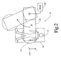
- a magnetic resonance imaging apparatus 10 includes a main magnet 20 which generates a main magnetic field through an examination region which is defined by opposing symmetrical magnetic pole pieces 22, 24 of the main magnet 20 .
- the pole pieces 22, 24 serve to improve the quality of the main magnetic field in the gap therebetween.
- the main magnetic field is a strong substantially uniform temporally constant field that is aligned with a z or vertical axis.
- the opposing magnetic pole pieces 22, 24 are connected by a ferrous flux return path 26 , such as a C- or U-shaped iron element.
- Resistive or superconducting main field coils 28, 30 are operated under control of a main magnetic field control circuit 32 to induce the main magnetic field between the opposing magnetic pole pieces 22, 24 in the examination region and a magnetic flux in the ferrous flux return path 26 .
- the iron element may be a permanent magnet which generates the main magnetic field within the examination region.
- the main field coils 28, 30 include coil segments disposed adjacent to or in conjunction with each of the opposing magnetic pole pieces 22, 24 .
- the main field coils 28, 30 can be disposed anywhere along the ferrous flux return path 26 .
- a magnetic resonance echo means operated under the control of a sequence control circuit 34 applies a series of radio frequency (RF) and magnetic field gradient pulses to invert or excite magnetic spins, induce magnetic resonance, refocus magnetic resonance, manipulate magnetic resonance, spatially and otherwise encode the magnetic resonance, to saturate spins, and the like to generate magnetic resonance imaging and spectroscopy sequences.
- RF radio frequency
- a gradient coil assembly 36 selectively creates magnetic gradients in the main magnetic field across the examination region via gradient current amplifiers 38 that apply electrical current pulses to the gradient coil assembly 36 .
- the gradient coil assembly includes self shielded gradient coils for producing magnetic gradients along three mutually orthogonal axes, x, y, and z.
- An RF transmitter 40 (optionally digital) transmits radio frequency pulses or pulse packets to a whole-body RF coil 42 disposed adjacent the examination region to transmit RF pulses into the examination region.
- a typical radio frequency pulse is composed of a packet of immediately contiguous pulse segments of short duration which taken together with each other and any applied gradients achieve a selected magnetic resonance manipulation.
- the RF pulses are used to saturate, excite resonance, invert magnetization, refocus resonance, or manipulate resonance in selected portions of the examination region.
- the resonance signals are commonly picked up by the whole-body RF coil 42 .
- the RF coil may be disposed near the opposing magnetic pole pieces 22, 24, (as is the whole-body RF coil 42 illustrated) or on the subject 44 being examined.
- a surface coil may be positioned contiguous to the subject 44 being examined for controllably inducing magnetic resonance in a selected region of the subject 44 .
- a receiver 46 receives signals from resonating dipoles within the examination region.
- the signals are received via the same RF coil that transmits the radio frequency pulses.
- separate receiver coils may be used.
- receive only surface coils may be disposed continuous to a selected region of the subject 44 being examined to receive resonance induced therein by the whole-body RF transmitting coil 42 surrounding the examination region.
- the sequence control circuit 32 controls the gradient pulse amplifiers 38 and the transmitter 40 to generate any of a plurality of multiple echo sequences, such as echo-planar imaging, echo-volume imaging, gradient and spin echo imaging, fast spin echo imaging, and the like.
- the receiver 46 receives a plurality of data inputs in rapid succession following each RF excitation pulse.
- the radio frequency signals received are demodulated and reconstructed into an image representation by a reconstruction processor 48 which applies a two-dimensional Fourier transform or other appropriate reconstruction algorithm.
- the image may represent a planar slice through the patient, an array of parallel planar slices, a three-dimensional volume, or the like.
- the image is then stored in an image memory 50 where it may be accessed by a display, such as a video monitor 52 which provides a human viewable display of the resultant image.
- a couch 54 suspends a subject 44 to be examined at least partially within the examination region (i.e., so that a region of interest is in the examination region).
- the couch 54 and consequently the subject 44 , remains substantially stationary throughout the magnetic resonance imaging process and throughout any accompanying surgical procedures.
- the main magnet 20 is ramped down and moved as indicated by the arrow so that the patient or subject 44 is wholly outside the examination region.
- the main magnet 20 is mounted on rollers or wheels 56 which engage a track 58 laid out on the floor. In this manner, the main magnet 20 can be translated to a remote location away from the subject 44 being examined. Hence, a surgical team is permitted unfettered access to the subject 44 .
- the main magnet 20 is repositioned about the subject 44 without moving the subject 44 . While depicted as being moved away from the couch 54 perpendicular to its longitudinal axis, depending on available space and design preferences, the main magnet 20 may be shifted in any desired direction, for example in a direction parallel to the longitudinal axis of the couch 54 .
- Drive systems 60 are employed to direct and/or facilitate the main magnet's movement such as motors, skids, hydraulics, gears, cable, pulleys, and the like.
- Brakes and guides (not illustrated) are employed for stationary placement and accurate alignment of the main magnet 20 .
- the main magnet 20 is moved by rotating it about a vertical axis to a position where the pole pieces 22, 24 are no longer on opposite sides of the subject 44 .
- the vertical axis of rotation is concentric with a vertically extending portion of the ferrous flux return path 26 .
- the vertical axis of rotation extends through the centre of gravity of the main magnet 20 .
- the MRI apparatus 10 includes a cylindrically shaped main magnet 20 for generating the main magnetic field horizontally through its central bore which defines the examination region.
- the main magnet 20 is moved by translating it in a direction parallel to its central axis.
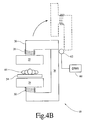
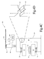
- the ferrous flux return path 26 is separated into two pieces or sections such that the upper piece along with the pole piece 22 , the main field coil 28 , and other associated structure is moved to a remote location.
- the ferrous flux return path is separated along the vertically extending portion thereof.
- the upper portion of the main magnet 20 is then selectively moved out of the way by either: rotating it about a vertical axis concentric with the vertically extending portion of the ferrous flux return path (as illustrated in FIGURE 4A); flipping it up about a hinge 62 (as illustrated in FIGURE 4B); lifting it up by a hoist, winch, or other like mechanism 64 and translating it along a track 58 in the ceiling to which the lifting mechanism is engaged via rollers or wheels 56 (as illustrated in FIGURES 4C and 4D); simply lifting or raising it to the ceiling; or by removing it to a remote location by other like mechanisms as design constraints and/or available space permits.
- associated structures e.g., track 58
- track 58 is constructed of a non-ferro magnetic material to avoid diversion and distortion of the magnetic flux.
- the two pieces of the ferrous flux return path 26 are fitted with at least one pin 80 on one piece of the ferrous flux return path 26 and at least one pin receptor 82 on the other.
- the pin 80 is received in the pin receptor 82 . That is so say, the pin 80 and pin receptor 82 cooperate to safeguard against misalignment of the pole pieces 22, 24 in that only when properly aligned will the pin receptor 82 accept the pin 80 .
- the abutting ends of the two pieces of the ferrous flux return path 26 may be cut or shaped in such a manner that only when the proper alignment is achieved will the two pieces fit together. The alignment is then automatically further secured, maintained, and fine tuned as the main magnet 20 is ramped up.
- the magnetic circuit in main magnet 20 seeks to achieve a minimum energy state as a system.
- any misaligned pole pieces 22, 24 exert forces to move themselves into alignment, as this is a minimum energy state for the system.
- the system's inclination to a minimum energy state exerts forces to minimize and close any gaps in the ferrous flux return path 26 .
- the sections on either side of the interface are pulled and/or attracted toward each other eliminating gaps and generating a frictional force therebetween fixing their relative orientation.
- the sections can be biased apart with spring members that are compressed by the magnetic forces to permit direct contact between the sections.
- the MRI apparatus 10 in the illustrated embodiment has a ferrous flux return path 26 divided into four parts 26a-d , each including a vertically extending column portion.
- Each column includes an upper and lower laterally extending portion associated with the pole pieces 22, 24 respectively.
- the laterally extending portions of each column meet at a central symmetrical location above and below the pole pieces 22, 24 .
- gaps 22g and 24g behind the pole pieces 22, 24 separate the pole pieces from the lateral extensions. This reduces the amount of material associated with the ferrous flux return path 26 , which in turn reduces its overall weight and eases mechanical constraints involved with its movement.
- the pole pieces 22, 24 are surrounded by resistive or superconducting main field coils 28, 30 .
- the coils are disposed in an annular helium cans 90 that are surrounded by vacuum dewars 92 .
- the pole pieces 22, 24 are preferably circularly symmetric with a symmetrically contoured face for improving the magnetic field in the gap therebetween.
- the pole pieces 22, 24 are disposed centrally and symmetrically with respect to the ferrous flux return path 26 . More specifically, the pole pieces 22, 24 are displaced from each other by a distance 2x and are each displaced from the upper and lower lateral extensions of the four columns by a distance 1x. Each main field coil 28, 30 and pole piece 22, 24 is attracted to a magnetic reflection of itself in the adjoining lateral extensions. By positioning the pole pieces 22, 24 symmetrically between each other and the lateral extensions, the attractive force between the main field coils 28, 30 is balanced against the attractive force between each main field coils 28, 30 and its attraction to its magnetic image mirrored in the lower and upper lateral extensions. The main field coils 28, 30 and pole pieces 22, 24 can be positioned such that the net magnetic forces on them can be perfectly balanced.
- FIGURE 5C an alternate embodiment of the magnetic resonance apparatus 10 illustrated in FIGURES 5A and 5B is shown having three ferrous flux return path 26a-c sections.
- the pole pieces 22, 24 are also divided into three sections 22a-c and 24a-c, respectively. Each portion of the pole pieces is moved with their respective sections of the ferrous flux return path 26a-c . Again, this lessens the mechanical constraints associated with the movement of any one section which otherwise would have the entire pole pieces connected thereto.
- entire pole piece 22 may be connected to one section of the ferrous flux return path, i.e., 26a
- the other pole piece 24 is connected to another section of the ferrous flux return path, i.e., 26b .
- the number of sections into which the ferrous flux return path 26 and/or the pole pieces 22, 24 are divided is not limited to the illustrated embodiments but may be any appropriate number for the particular design parameters.
- the spacing between and the arrangement of structures of the MRI assembly 10 is selected to be an appropriate height for attending physicians and equipment positioned therein, typically 240 cm or more.
- the lateral extensions include projections 102, 104, respectively, which are spaced about 130 cm from each other.
- the projections 102, 104 need not be the same. Rather, their relative projection is selected such that a horizontal centre of the examination region is at a convenient height for attending physicians, attendants, and technicians.
- one or more of the U- or C-shaped columns 26a-d is separated and moved individually to remote locations by any of the previously described procedures as may be appropriate given the particular design parameters. In this manner, the weight load is divided a number of times and individual mechanical constraints associated with the movement of each pieces is significantly reduced.
Landscapes
- Physics & Mathematics (AREA)
- Condensed Matter Physics & Semiconductors (AREA)
- General Physics & Mathematics (AREA)
- Magnetic Resonance Imaging Apparatus (AREA)
Applications Claiming Priority (2)
| Application Number | Priority Date | Filing Date | Title |
|---|---|---|---|
| US44425 | 1979-06-01 | ||
| US09/044,425 US6029081A (en) | 1998-03-19 | 1998-03-19 | Movable magnets for magnetic resonance surgery |
Publications (3)
| Publication Number | Publication Date |
|---|---|
| EP0943929A2 true EP0943929A2 (fr) | 1999-09-22 |
| EP0943929A3 EP0943929A3 (fr) | 2000-04-19 |
| EP0943929B1 EP0943929B1 (fr) | 2006-06-14 |
Family
ID=21932320
Family Applications (1)
| Application Number | Title | Priority Date | Filing Date |
|---|---|---|---|
| EP99302075A Expired - Lifetime EP0943929B1 (fr) | 1998-03-19 | 1999-03-18 | Appareil à résonance magnétique |
Country Status (3)
| Country | Link |
|---|---|
| US (1) | US6029081A (fr) |
| EP (1) | EP0943929B1 (fr) |
| DE (1) | DE69931833T2 (fr) |
Cited By (3)
| Publication number | Priority date | Publication date | Assignee | Title |
|---|---|---|---|---|
| DE19923947A1 (de) * | 1999-05-25 | 2000-12-07 | Siemens Ag | Magnetresonanztomographiegerät, insbesondere für den interoperativen Einsatz |
| WO2009001084A1 (fr) * | 2007-06-26 | 2008-12-31 | Oxford Instruments Plc | Système d'aimant pour utilisation dans l'imagerie par résonance magnétique |
| EP2034889A1 (fr) * | 2006-06-20 | 2009-03-18 | IMRIS Inc | Scanner intégré rotatif pour des applications d'imagerie diagnostiques et chirurgicales |
Families Citing this family (21)
| Publication number | Priority date | Publication date | Assignee | Title |
|---|---|---|---|---|
| CN1230120C (zh) * | 1997-05-23 | 2005-12-07 | 普罗里森姆股份有限公司 | 由mri引导的治疗装置 |
| US6317618B1 (en) * | 1999-06-02 | 2001-11-13 | Odin Technologies Ltd. | Transportable intraoperative magnetic resonance imaging apparatus |
| US7313429B2 (en) | 2002-01-23 | 2007-12-25 | Stereotaxis, Inc. | Rotating and pivoting magnet for magnetic navigation |
| US7019610B2 (en) * | 2002-01-23 | 2006-03-28 | Stereotaxis, Inc. | Magnetic navigation system |
| US6946840B1 (en) * | 2001-03-08 | 2005-09-20 | General Electric Company | Integrated and independently controlled transmit only and receive only coil arrays for magnetic resonance systems |
| DE10114013B4 (de) * | 2001-03-22 | 2005-06-23 | Siemens Ag | Magnetresonanzanlage |
| GB0211516D0 (en) * | 2002-05-20 | 2002-06-26 | Univ Sheffield | Method and apparatus for magnetic resonance imaging |
| US7215231B1 (en) | 2002-08-16 | 2007-05-08 | Fonar Corporation | MRI system |
| ITSV20020057A1 (it) * | 2002-11-28 | 2004-05-29 | Esaote Spa | Combinazione di macchina per rilevamento di immagini in risonanza nucleare e lettino porta paziente |
| US7774046B2 (en) * | 2003-03-13 | 2010-08-10 | Stereotaxis, Inc. | Magnetic navigation system |
| US20050182315A1 (en) * | 2003-11-07 | 2005-08-18 | Ritter Rogers C. | Magnetic resonance imaging and magnetic navigation systems and methods |
| US7274192B2 (en) * | 2005-05-31 | 2007-09-25 | General Electric Company | Combined open and closed magnet configuration for MRI |
| US8710839B2 (en) * | 2008-12-12 | 2014-04-29 | Yale University | O-space imaging: highly efficient parallel imaging using complementary nonlinear encoding gradient fields and receive coil geometries |
| US8844470B2 (en) | 2010-09-27 | 2014-09-30 | Aspect Imaging Ltd | Maneuverable bed for analyzed objects |
| US10292617B2 (en) | 2010-09-30 | 2019-05-21 | Aspect Imaging Ltd. | Automated tuning and frequency matching with motor movement of RF coil in a magnetic resonance laboratory animal handling system |
| DE202011051404U1 (de) | 2011-09-22 | 2011-11-02 | Aspect Magnet Technologies Ltd. | Bewegliches Bett für Analyseobjekte |
| EP3189344A4 (fr) * | 2014-09-05 | 2018-06-13 | Hyperfine Research Inc. | Procédés et appareil de gestion thermique |
| DE202015103602U1 (de) | 2015-06-18 | 2015-08-20 | Aspect Imaging Ltd. | Vorrichtung zur dreidimensionalen anatomischen Bildgebung und Bestrahlungstherapie |
| US10539637B2 (en) | 2016-11-22 | 2020-01-21 | Hyperfine Research, Inc. | Portable magnetic resonance imaging methods and apparatus |
| US10627464B2 (en) | 2016-11-22 | 2020-04-21 | Hyperfine Research, Inc. | Low-field magnetic resonance imaging methods and apparatus |
| DE102019220506A1 (de) * | 2019-12-23 | 2021-06-24 | Robert Bosch Gesellschaft mit beschränkter Haftung | Erfassungsvorrichtung für ein Fördersystem |
Citations (9)
| Publication number | Priority date | Publication date | Assignee | Title |
|---|---|---|---|---|
| JPS62196803A (ja) * | 1986-02-24 | 1987-08-31 | Hitachi Medical Corp | 核磁気共鳴イメ−ジング装置 |
| JPS63286142A (ja) * | 1987-05-19 | 1988-11-22 | Toshiba Corp | 磁気共鳴イメ−ジング装置 |
| US4875485A (en) * | 1985-11-18 | 1989-10-24 | Kabushiki Kaisha Toshiba | Magnetic resonance system |
| JPH04371136A (ja) * | 1991-06-19 | 1992-12-24 | Hitachi Medical Corp | Mri装置用静磁場発生装置 |
| US5517121A (en) * | 1995-01-13 | 1996-05-14 | Toshiba America Mri, Inc. | MRI system with side-access to an image volume located within a two-column main magnet |
| JPH0994234A (ja) * | 1995-09-29 | 1997-04-08 | Olympus Optical Co Ltd | Mri装置 |
| WO1997035206A1 (fr) * | 1996-03-15 | 1997-09-25 | National Research Council Of Canada | Intervention chirurgicale recourant a l'imagerie par resonance magnetique |
| JPH1043159A (ja) * | 1996-08-07 | 1998-02-17 | Olympus Optical Co Ltd | 治療用mri装置 |
| EP0918229A2 (fr) * | 1997-11-18 | 1999-05-26 | Picker International, Inc. | Système d'aimants |
Family Cites Families (36)
| Publication number | Priority date | Publication date | Assignee | Title |
|---|---|---|---|---|
| US36099A (en) * | 1862-08-05 | Improved fan-shaped sail | ||
| US4337449A (en) * | 1979-06-25 | 1982-06-29 | Portescap | Magnetic transducer with a movable magnet |
| FI65365C (fi) * | 1982-07-07 | 1984-05-10 | Instrumentarium Oy | Spolanordning |
| JPS63307711A (ja) * | 1987-06-10 | 1988-12-15 | Toshiba Corp | 磁石装置 |
| JPS63309248A (ja) * | 1987-06-11 | 1988-12-16 | Toshiba Corp | Mri用表面コイル装置 |
| US4985678A (en) * | 1988-10-14 | 1991-01-15 | Picker International, Inc. | Horizontal field iron core magnetic resonance scanner |
| EP0365737B1 (fr) * | 1988-10-25 | 1993-05-12 | Siemens Aktiengesellschaft | Appareil d'examen par radiographie |
| US5150710A (en) * | 1989-04-21 | 1992-09-29 | Webb Research Ii, Inc. | Variable position surface coil stabilizer for magnetic resonance imaging |
| DE4024582C2 (de) * | 1989-08-16 | 1996-08-14 | Siemens Ag | Hochfrequenz-Antenne eines Kernspintomographen |
| US5086448A (en) * | 1989-12-22 | 1992-02-04 | Muthmann Karl Dieter | X-ray examination unit |
| US5014292A (en) * | 1990-01-29 | 1991-05-07 | Siczek Bernard W | Tiltable x-ray table integrated with carriage for x-ray source and receptor |
| FI86687C (fi) * | 1990-06-14 | 1992-10-12 | Instrumentarium Oy | Patientbaedd foer magnetavbildningsanordning |
| US5155757A (en) * | 1990-06-20 | 1992-10-13 | Kabushiki Kaisha Toshiba | X-ray diagnosing apparatus |
| US5221902A (en) * | 1990-10-22 | 1993-06-22 | Medical Advances, Inc. | NMR neck coil with passive decoupling |
| DE59108314D1 (de) * | 1990-11-30 | 1996-12-05 | Siemens Ag | Homogenfeldmagnet mit mindestens einer mechanisch auszurichtenden Polplatte |
| US5153546A (en) * | 1991-06-03 | 1992-10-06 | General Electric Company | Open MRI magnet |
| GB9206014D0 (en) * | 1992-03-19 | 1992-04-29 | Oxford Instr Ltd | Magnet assembly |
| DE4214087C1 (en) * | 1992-04-29 | 1993-05-27 | Siemens Ag, 8000 Muenchen, De | System for holding X=ray transmitter and receiver - has two C=shaped curved arms, one for carrying the transmitter and receiver and the other for carrying the first arm |
| US5386453A (en) * | 1992-05-12 | 1995-01-31 | Diasonics, Inc. | Imaging and treatment apparatus having a floor-mounted guiding track |
| JP3742662B2 (ja) * | 1992-08-05 | 2006-02-08 | ゼネラル・エレクトリック・カンパニイ | 開放形磁気共鳴イメージングに適した磁石 |
| JPH06121779A (ja) * | 1992-10-12 | 1994-05-06 | Toshiba Corp | 磁気共鳴イメージング装置 |
| US5378988A (en) * | 1993-01-22 | 1995-01-03 | Pulyer; Yuly M. | MRI system having high field strength open access magnet |
| GB2278685B (en) * | 1993-05-27 | 1997-07-30 | Elscint Ltd | Superconducting magnet |
| US5307806A (en) * | 1993-08-10 | 1994-05-03 | Board Of Regents Of Univ. Of Nebraska | NMR pelvic coil |
| FI933834A (fi) * | 1993-09-01 | 1995-03-02 | Picker Nordstar Oy | Magneettikuvauslaitteen napakenkä |
| JPH0767870A (ja) * | 1993-09-02 | 1995-03-14 | Sony Corp | 医用検査装置と医用検査装置の患者テーブルの移動検出方法 |
| DE69419096T2 (de) * | 1993-09-29 | 1999-10-28 | Oxford Magnet Tech | Verbesserungen an Magneten der Bilderzeugung mittels magnetischer Resonanz |
| DE4335306A1 (de) * | 1993-10-16 | 1995-04-20 | Philips Patentverwaltung | Röntgenuntersuchungsgerät |
| US5541856A (en) * | 1993-11-08 | 1996-07-30 | Imaging Systems International | X-ray inspection system |
| US5423315A (en) * | 1993-11-22 | 1995-06-13 | Picker International, Inc. | Magnetic resonance imaging system with thin cylindrical uniform field volume and moving subjects |
| US5521957A (en) * | 1994-03-15 | 1996-05-28 | Hansen; Steven J. | X-ray imaging system |
| US5663645A (en) * | 1994-08-02 | 1997-09-02 | Toshiba America Mri Inc. | Spatially orthogonal rectangular coil pair suitable for vertical magnetic field MRI system |
| JP2776275B2 (ja) * | 1994-10-31 | 1998-07-16 | 株式会社島津製作所 | X線透視撮影装置 |
| US5528212A (en) * | 1995-03-09 | 1996-06-18 | Sti Optronics, Inc. | Method and apparatus for control of a magnetic structure |
| GB2300712A (en) * | 1995-05-11 | 1996-11-13 | Elscint Ltd | Rotatable MRI magnet and patient support |
| US5627873B1 (en) * | 1995-08-04 | 2000-03-14 | Oec Medical Systems | Mini c-arm assembly for mobile x-ray imaging system |
-
1998
- 1998-03-19 US US09/044,425 patent/US6029081A/en not_active Expired - Fee Related
-
1999
- 1999-03-18 EP EP99302075A patent/EP0943929B1/fr not_active Expired - Lifetime
- 1999-03-18 DE DE69931833T patent/DE69931833T2/de not_active Expired - Fee Related
Patent Citations (9)
| Publication number | Priority date | Publication date | Assignee | Title |
|---|---|---|---|---|
| US4875485A (en) * | 1985-11-18 | 1989-10-24 | Kabushiki Kaisha Toshiba | Magnetic resonance system |
| JPS62196803A (ja) * | 1986-02-24 | 1987-08-31 | Hitachi Medical Corp | 核磁気共鳴イメ−ジング装置 |
| JPS63286142A (ja) * | 1987-05-19 | 1988-11-22 | Toshiba Corp | 磁気共鳴イメ−ジング装置 |
| JPH04371136A (ja) * | 1991-06-19 | 1992-12-24 | Hitachi Medical Corp | Mri装置用静磁場発生装置 |
| US5517121A (en) * | 1995-01-13 | 1996-05-14 | Toshiba America Mri, Inc. | MRI system with side-access to an image volume located within a two-column main magnet |
| JPH0994234A (ja) * | 1995-09-29 | 1997-04-08 | Olympus Optical Co Ltd | Mri装置 |
| WO1997035206A1 (fr) * | 1996-03-15 | 1997-09-25 | National Research Council Of Canada | Intervention chirurgicale recourant a l'imagerie par resonance magnetique |
| JPH1043159A (ja) * | 1996-08-07 | 1998-02-17 | Olympus Optical Co Ltd | 治療用mri装置 |
| EP0918229A2 (fr) * | 1997-11-18 | 1999-05-26 | Picker International, Inc. | Système d'aimants |
Non-Patent Citations (4)
| Title |
|---|
| PATENT ABSTRACTS OF JAPAN vol. 012, no. 049 (E-582), 13 February 1988 (1988-02-13) & JP 62 196803 A (HITACHI MEDICAL CORP), 31 August 1987 (1987-08-31) * |
| PATENT ABSTRACTS OF JAPAN vol. 013, no. 111 (C-577), 16 March 1989 (1989-03-16) & JP 63 286142 A (TOSHIBA CORP), 22 November 1988 (1988-11-22) * |
| PATENT ABSTRACTS OF JAPAN vol. 017, no. 243 (C-1058), 17 May 1993 (1993-05-17) & JP 04 371136 A (HITACHI MEDICAL CORP), 24 December 1992 (1992-12-24) * |
| PATENT ABSTRACTS OF JAPAN vol. 1997, no. 08, 29 August 1997 (1997-08-29) & JP 09 094234 A (OLYMPUS OPTICAL CO LTD), 8 April 1997 (1997-04-08) * |
Cited By (4)
| Publication number | Priority date | Publication date | Assignee | Title |
|---|---|---|---|---|
| DE19923947A1 (de) * | 1999-05-25 | 2000-12-07 | Siemens Ag | Magnetresonanztomographiegerät, insbesondere für den interoperativen Einsatz |
| EP2034889A1 (fr) * | 2006-06-20 | 2009-03-18 | IMRIS Inc | Scanner intégré rotatif pour des applications d'imagerie diagnostiques et chirurgicales |
| EP2034889A4 (fr) * | 2006-06-20 | 2012-10-10 | Imris Inc | Scanner intégré rotatif pour des applications d'imagerie diagnostiques et chirurgicales |
| WO2009001084A1 (fr) * | 2007-06-26 | 2008-12-31 | Oxford Instruments Plc | Système d'aimant pour utilisation dans l'imagerie par résonance magnétique |
Also Published As
| Publication number | Publication date |
|---|---|
| EP0943929A3 (fr) | 2000-04-19 |
| DE69931833D1 (de) | 2006-07-27 |
| EP0943929B1 (fr) | 2006-06-14 |
| US6029081A (en) | 2000-02-22 |
| DE69931833T2 (de) | 2007-01-11 |
Similar Documents
| Publication | Publication Date | Title |
|---|---|---|
| US6029081A (en) | Movable magnets for magnetic resonance surgery | |
| US6507192B1 (en) | Nuclear magnetic resonance apparatus and methods of use and facilities for incorporating the same | |
| US6496007B1 (en) | MRI apparatus | |
| US6828792B1 (en) | MRI apparatus and method for imaging | |
| US10852375B1 (en) | Magnetic resonance imaging method and apparatus | |
| US20050154291A1 (en) | Method of using a small MRI scanner | |
| US20100060282A1 (en) | Three-dimensional asymmetric transverse gradient coils | |
| CN111913142B (zh) | 基本场磁体装置、磁共振断层造影系统和测量方法 | |
| EP0637755A1 (fr) | Appareil pour l'imagerie par résonance magnétique | |
| EP2353170B1 (fr) | Electroaimant | |
| US7560928B2 (en) | Magnetic resonance imaging system, apparatus and associated methods | |
| WO2006088453A1 (fr) | Procede d’utilisation d’un petit scanner irm | |
| EP0318257B1 (fr) | Dispositions de bobines pour un appareil de résonance magnétique | |
| US6147495A (en) | Magnetic resonance imaging with integrated poleface features | |
| US10823793B2 (en) | Resonance data acquisition scanner with rotating basic field magnet | |
| US7127802B1 (en) | Method of fabricating a composite plate | |
| JPH01305937A (ja) | 磁気共鳴診断装置 | |
| JP3112474B2 (ja) | 磁気共鳴イメージング装置 | |
| US20080204016A1 (en) | Magnetic Resonance Apparatus and Method | |
| JP2003126061A (ja) | 顕微鏡付き画像診断装置 |
Legal Events
| Date | Code | Title | Description |
|---|---|---|---|
| PUAI | Public reference made under article 153(3) epc to a published international application that has entered the european phase |
Free format text: ORIGINAL CODE: 0009012 |
|
| AK | Designated contracting states |
Kind code of ref document: A2 Designated state(s): DE FR GB NL |
|
| AX | Request for extension of the european patent |
Free format text: AL;LT;LV;MK;RO;SI |
|
| PUAL | Search report despatched |
Free format text: ORIGINAL CODE: 0009013 |
|
| AK | Designated contracting states |
Kind code of ref document: A3 Designated state(s): AT BE CH CY DE DK ES FI FR GB GR IE IT LI LU MC NL PT SE |
|
| AX | Request for extension of the european patent |
Free format text: AL;LT;LV;MK;RO;SI |
|
| 17P | Request for examination filed |
Effective date: 20001011 |
|
| AKX | Designation fees paid |
Free format text: DE FR GB NL |
|
| RAP1 | Party data changed (applicant data changed or rights of an application transferred) |
Owner name: MARCONI MEDICAL SYSTEMS, INC. |
|
| RAP1 | Party data changed (applicant data changed or rights of an application transferred) |
Owner name: PHILIPS MEDICAL SYSTEMS (CLEVELAND), INC. |
|
| RAP1 | Party data changed (applicant data changed or rights of an application transferred) |
Owner name: KONINKLIJKE PHILIPS ELECTRONICS N.V. |
|
| 17Q | First examination report despatched |
Effective date: 20050223 |
|
| GRAP | Despatch of communication of intention to grant a patent |
Free format text: ORIGINAL CODE: EPIDOSNIGR1 |
|
| GRAS | Grant fee paid |
Free format text: ORIGINAL CODE: EPIDOSNIGR3 |
|
| GRAA | (expected) grant |
Free format text: ORIGINAL CODE: 0009210 |
|
| AK | Designated contracting states |
Kind code of ref document: B1 Designated state(s): DE FR GB NL |
|
| PG25 | Lapsed in a contracting state [announced via postgrant information from national office to epo] |
Ref country code: NL Free format text: LAPSE BECAUSE OF FAILURE TO SUBMIT A TRANSLATION OF THE DESCRIPTION OR TO PAY THE FEE WITHIN THE PRESCRIBED TIME-LIMIT Effective date: 20060614 |
|
| REG | Reference to a national code |
Ref country code: GB Ref legal event code: FG4D |
|
| REG | Reference to a national code |
Ref country code: GB Ref legal event code: 746 Effective date: 20060616 |
|
| REF | Corresponds to: |
Ref document number: 69931833 Country of ref document: DE Date of ref document: 20060727 Kind code of ref document: P |
|
| NLV1 | Nl: lapsed or annulled due to failure to fulfill the requirements of art. 29p and 29m of the patents act | ||
| PLBE | No opposition filed within time limit |
Free format text: ORIGINAL CODE: 0009261 |
|
| STAA | Information on the status of an ep patent application or granted ep patent |
Free format text: STATUS: NO OPPOSITION FILED WITHIN TIME LIMIT |
|
| EN | Fr: translation not filed | ||
| 26N | No opposition filed |
Effective date: 20070315 |
|
| PG25 | Lapsed in a contracting state [announced via postgrant information from national office to epo] |
Ref country code: FR Free format text: LAPSE BECAUSE OF FAILURE TO SUBMIT A TRANSLATION OF THE DESCRIPTION OR TO PAY THE FEE WITHIN THE PRESCRIBED TIME-LIMIT Effective date: 20070309 |
|
| PG25 | Lapsed in a contracting state [announced via postgrant information from national office to epo] |
Ref country code: FR Free format text: LAPSE BECAUSE OF FAILURE TO SUBMIT A TRANSLATION OF THE DESCRIPTION OR TO PAY THE FEE WITHIN THE PRESCRIBED TIME-LIMIT Effective date: 20060614 |
|
| PGFP | Annual fee paid to national office [announced via postgrant information from national office to epo] |
Ref country code: DE Payment date: 20090512 Year of fee payment: 11 |
|
| PG25 | Lapsed in a contracting state [announced via postgrant information from national office to epo] |
Ref country code: DE Free format text: LAPSE BECAUSE OF NON-PAYMENT OF DUE FEES Effective date: 20101001 |
|
| PGFP | Annual fee paid to national office [announced via postgrant information from national office to epo] |
Ref country code: GB Payment date: 20120402 Year of fee payment: 14 |
|
| GBPC | Gb: european patent ceased through non-payment of renewal fee |
Effective date: 20130318 |
|
| PG25 | Lapsed in a contracting state [announced via postgrant information from national office to epo] |
Ref country code: GB Free format text: LAPSE BECAUSE OF NON-PAYMENT OF DUE FEES Effective date: 20130318 |