EP0943378A2 - Device for the feeding and lateral displacement of rolled wire loops - Google Patents
Device for the feeding and lateral displacement of rolled wire loops Download PDFInfo
- Publication number
- EP0943378A2 EP0943378A2 EP99104713A EP99104713A EP0943378A2 EP 0943378 A2 EP0943378 A2 EP 0943378A2 EP 99104713 A EP99104713 A EP 99104713A EP 99104713 A EP99104713 A EP 99104713A EP 0943378 A2 EP0943378 A2 EP 0943378A2
- Authority
- EP
- European Patent Office
- Prior art keywords
- bundle
- swivel
- forming chamber
- chamber
- thrust drive
- Prior art date
- Legal status (The legal status is an assumption and is not a legal conclusion. Google has not performed a legal analysis and makes no representation as to the accuracy of the status listed.)
- Withdrawn
Links
- 238000006073 displacement reaction Methods 0.000 title claims description 8
- 238000004804 winding Methods 0.000 claims description 13
- 238000000576 coating method Methods 0.000 claims description 2
- 238000000034 method Methods 0.000 abstract description 3
- 239000002184 metal Substances 0.000 abstract 2
- 238000005096 rolling process Methods 0.000 abstract 1
- 230000005540 biological transmission Effects 0.000 description 2
- 230000000694 effects Effects 0.000 description 2
- 230000015572 biosynthetic process Effects 0.000 description 1
- 230000001419 dependent effect Effects 0.000 description 1
- 238000003780 insertion Methods 0.000 description 1
- 230000037431 insertion Effects 0.000 description 1
- 230000007257 malfunction Effects 0.000 description 1
- 230000008439 repair process Effects 0.000 description 1
Images
Classifications
-
- B—PERFORMING OPERATIONS; TRANSPORTING
- B21—MECHANICAL METAL-WORKING WITHOUT ESSENTIALLY REMOVING MATERIAL; PUNCHING METAL
- B21C—MANUFACTURE OF METAL SHEETS, WIRE, RODS, TUBES OR PROFILES, OTHERWISE THAN BY ROLLING; AUXILIARY OPERATIONS USED IN CONNECTION WITH METAL-WORKING WITHOUT ESSENTIALLY REMOVING MATERIAL
- B21C47/00—Winding-up, coiling or winding-off metal wire, metal band or other flexible metal material characterised by features relevant to metal processing only
- B21C47/02—Winding-up or coiling
- B21C47/10—Winding-up or coiling by means of a moving guide
- B21C47/14—Winding-up or coiling by means of a moving guide by means of a rotating guide, e.g. laying the material around a stationary reel or drum
- B21C47/146—Controlling or influencing the laying pattern of the coils
Definitions
- the invention relates to a device for guiding and Transverse displacement of wire rod turns by means of a conveyor transported in an approximately horizontal position to form wire coils into an upright cylindrical bundling chamber to be thrown into the area of the interior of the bundle chamber insertable and extractable, which act on the wire rod windings Cross slide elements.
- Devices of this type come in a wide variety of forms has been developed; they serve the goal, which come from one, in a wire rod mill rolled wire by means of a winding layer, overlapping one another and possibly cooled on the conveyor or otherwise treated wire rod windings that their dropping into the bundle chamber depending on the transport speed, the wire diameter and its metallic Structure shifted more or less unevenly against each other lay on top of each other, load laterally and move that a bundle of evenly lying turns is formed becomes.
- the invention is based, the generic form of training the task to improve the device so that these listed Disadvantages are avoided.
- transverse displacement device swivel brackets suspended outside the bundle chamber consist of vertical slot recesses in the cylinder wall the fret chamber can be swung in and out of its interior are.
- This can be done according to the invention outside of Interior of the bundle chamber arranged with the swivel tabs connected, jointly or independently operable, hydraulic, pneumatic or electromagnetic thrust drive units be effected.
- the transverse displacement device swivel brackets suspended outside the bundle chamber consist of vertical slot recesses in the cylinder wall the fret chamber can be swung in and out of its interior are.
- This can be done according to the invention outside of Interior of the bundle chamber arranged with the swivel tabs connected, jointly or independently operable, hydraulic, pneumatic or electromagnetic thrust drive units be effected.
- Likewise in itself known, comprising the bundle forming chamber with a radial distance, rotatably mounted and drivable eccentric rings or cam rings or use individual cam drives as thrust drive units.
- the drives can be individually, sequentially or group-
- the swivel brackets should move into the Slot recesses of the Bundsenthunt be fitted, and the Surface section of the swivel brackets that acts on wire rod windings can, according to the invention, be flat or transverse to the tab longitudinal direction slightly arched and hardened and / or gliding Have coatings.
- the invention allows, besides avoiding the enumerated Disadvantages the length of the displacement of the swivel tabs and their Adjusting the cycle sequence according to the respective operating requirements to change or remove them completely from the drop area of the To bring out wire rod windings in the bundle forming chamber; this using conventional drive and control devices.
- the swivel tabs 3 are with With the help of these thrust drive units 4a and 4b through longitudinal slots 1c in the wall of the bundle forming chamber 1 in the interior of the latter Chamber swung in and out again. These swivel movements are with the help of a sequence control device, not shown for the thrust drive units 4a, 4b in the bundle forming chamber 1 moved in and out as indicated in Fig. 2, d. H. so that the turns S in the circumferential direction of an eccentric circle Center axis of the bundle chamber 1 are applied.
- the swivel plates 3 are with their thrust drive units 4a and 4b, as indicated by broken lines in Fig. 2, on segment support plates 14 arranged with the help of pressurized medium Piston-cylinder units 15 pivoted out of the support housing 1 can be to z.
- the Bundsentehunt 1 for that lateral removal of the mandrel 5 with the collar or that Highlighting the federal government in the event of operational disruptions or for assembly or To make repairs free. There is the possibility this process using appropriate safety switching elements trigger automatically.
- the swivel tabs 3 are through one, mounted in the carrying case 1a, by a motor 12 Pinion 12a rotating eccentric 7 (see also Fig. 4) on rollers 8 mounted in transmission rods 13 against the effect of return springs 9 actuated.
Landscapes
- Engineering & Computer Science (AREA)
- Mechanical Engineering (AREA)
- Winding, Rewinding, Material Storage Devices (AREA)
- Wire Processing (AREA)
Abstract
Description
Die Erfindung bezieht sich auf eine Vorrichtung zur Führung und Querverschiebung von Walzdrahtwindungen, die mittels eines Förderers in etwa horizontaler Lage herantransportiert zur Bildung von Drahtbunden in eine aufrecht stehende zylindrische Bundbildekammer abgeworfen werden, mit in den Bereich des Innenraums der Bundbildekammer ein- und ausbringbaren, die Walzdrahtwindungen beaufschlagenden Querverschiebeelementen.The invention relates to a device for guiding and Transverse displacement of wire rod turns by means of a conveyor transported in an approximately horizontal position to form wire coils into an upright cylindrical bundling chamber to be thrown into the area of the interior of the bundle chamber insertable and extractable, which act on the wire rod windings Cross slide elements.
Vorrichtungen dieser Art sind in unterschiedlichsten Ausbildungsformen entwickelt worden; sie dienen dem Ziel, die aus einem, in einer Walzdrahtstraße gewalzten Draht mittels eines Windungslegers, einander überlappend auf dem Förderer abgelegten und ggfs. gekühlten oder auf andere Weise behandelten Walzdrahtwindungen, die sich nach ihrem Abwurf in die Bundbildekammer in Abhängigkeit von der Transportgeschwindigkeit, dem Drahtdurchmesser und ihrer metallischen Struktur mehr oder weniger ungleichmäßig gegeneinander verschoben aufeinanderlegen, seitlich zu beaufschlagen und so zu verschieben, daß ein Bund gleichmäßig aufeinanderliegender Windungen gebildet wird.Devices of this type come in a wide variety of forms has been developed; they serve the goal, which come from one, in a wire rod mill rolled wire by means of a winding layer, overlapping one another and possibly cooled on the conveyor or otherwise treated wire rod windings that their dropping into the bundle chamber depending on the transport speed, the wire diameter and its metallic Structure shifted more or less unevenly against each other lay on top of each other, load laterally and move that a bundle of evenly lying turns is formed becomes.
Neben einer Vorrichtung, bei der im oberen Bereich der Bundbildekammer
Leitelemente mit exzentrisch zu der Innenfläche verlaufenden
Führungsbahnen angeordnet sind (EP 583 099 B1) wurde auch eine
Vorrichtung bekannt, bei der ein Mittenabschnitt der Bundbildekammer
als selbständiger, exzentrisch zu der Mittenachse rotierender
Ringkörper ausgebildet ist (EP 686 439 A1) und weiter ein, nicht
vorveröffentlichter Vorschlag, oberhalb der Einwurfmündung der
Bundbildekammer einen solchen, hier trichterförmigen Ringkörper
vorzusehen (DE 1 970 04 421).In addition to a device in the upper area of the bundle chamber
Guide elements with eccentric to the inner surface
Guideways are arranged (EP 583 099 B1) was also a
Apparatus known in which a central portion of the fret chamber
as an independent, rotating eccentrically to the central axis
Ring body is formed (EP 686 439 A1) and further, not
Pre-published proposal, above the mouth of the
Bundbildekammer such a funnel-shaped ring body
to be provided (
Nach einem weiteren Vorschlag (EP 686 438 A1) bestehen die Querverschiebeelemente aus, um vertikale bzw. zur Vertikalen geneigte Achsen rotierend antreibbaren Ballenkörpern mit zur Achse asymmetrisch verlaufenden Querschnitt. Diese Ballenkörper sind um einen, seitlich offenen Abschnitt der Bundbildekammer herum angeordnet und beaufschlagen, gemeinsam angetrieben, umlaufend die herabfallenden Walzendrahtwindungen, ähnlich wie die, schon beschriebenen exzentrisch umlaufenden Ringkörper.According to a further proposal (EP 686 438 A1) there are the transverse displacement elements to vertical or inclined to the vertical Axes rotatingly drivable bale bodies with asymmetrical to the axis trending cross section. These bale bodies are around one, laterally open section of the fret chamber arranged around and act, driven together, all around the falling Rolled wire windings, similar to the one already described, eccentrically encircling ring body.
Die Nachteile dieser bekannten Vorrichtungen bestehen einmal darin, daß die jeweiligen absoluten Verschiebeweglängen der Querverschiebeeinrichtungen nicht veränderbar sind. Eine solche Veränderung ist z. B. wünschenswert, wenn unterschiedliche Eigenschaften der Walzdrahtwindungen (Werkstoffhärte, Durchmesser) dies zweckmäßig erscheinen lassen, weiter darin, daß sich die Vorrichtung bei Betriebsstörungen, wie z. B. Überschreitung der vorgegebenen maximalen Bundhöhe, Einklemmen der Drahtspitze oder der Drahtwindungen durch die Querverschiebeelemente selbst oder deren Einführschlitze in der Zylinderwand der Bundbildekammer, nicht oder nur sehr schwierig aus dem lichten Fallbereich der Walzdrahtwindungen und aus der Bundbildekammer selbst herausbringen lassen und schließlich noch darin, daß einige der bekannten Vorrichtungen es nicht zulassen, den Fallquerschnitt der Bundbildekammer ganz frei zu machen, z. B. bei der Bildung von Bunden aus sehr dickem Draht, der dabei keiner Querverschiebebeaufschlagung seiner Windungen benötigt. The disadvantages of these known devices are that the respective absolute displacement lengths of the transverse displacement devices cannot be changed. Such a change is e.g. B. desirable if different properties of the wire rod windings (Material hardness, diameter) this seems appropriate can be further in that the device in the event of malfunctions, such as B. Exceeding the predetermined maximum Collar height, pinching the wire tip or the wire windings the transverse sliding elements themselves or their insertion slots in the Cylinder wall of the bundle chamber, not or only with great difficulty the clear fall area of the rolled wire turns and from the bundle forming chamber let yourself be brought out and finally in that some of the known devices do not allow the To make the cross section of the bundle chamber completely free, e.g. B. at the formation of bundles from very thick wire, which none Transverse loading of its windings needed.
Der Erfindung liegt die Aufgabe zugrunde, die gattungsgemäße Ausbildungsform der Vorrichtung so zu verbessern, daß diese aufgeführten Nachteile vermieden werden.The invention is based, the generic form of training the task to improve the device so that these listed Disadvantages are avoided.
Diese Aufgabe wird dadurch gelöst, daß die Querverschiebeeinrichtung aus, außerhalb der Bundbildekammer hängend gelagerten Schwenklaschen bestehen, die durch senkrechte Schlitzausnehmungen in der Zylinderwand der Bundbildekammer in deren Innenraum ein- und herausschwenkbar sind. Dies kann erfindungsgemäß durch außerhalb des Innenraums der Bundbildekammer angeordnete, mit den Schwenklaschen verbundene, gemeinsam oder unabhängig voneinander betätigbare, hydraulisch, pneumatisch oder elektromagnetisch arbeitende Schub-Antriebsaggregate bewirkt werden. Ebenso lassen sich auch an sich bekannte, die Bundbildekammer mit radialem Abstand umfassend, drehbar gelagerte und antreibbare Exzenterringe oder Nockenringe bzw. einzelne Nockentriebe als Schubantriebsaggregate verwenden. Die Antriebe können dabei einzel-, folge- oder gruppengesteuert werden. Die Schwenklaschen sollten mit leichtem Spiel in die in die Schlitzausnehmungen der Bundbildekammer eingepaßt sein, und die die Walzdrahtwindungen beaufschlagenden Flächenabschnitt der Schwenklaschen können erfindungsgemäß eben oder quer zur Laschenlängsrichtung leicht gewölbt verlaufen und gehärtete und/oder gleitfördernde Beschichtungen aufweisen.This object is achieved in that the transverse displacement device swivel brackets suspended outside the bundle chamber consist of vertical slot recesses in the cylinder wall the fret chamber can be swung in and out of its interior are. This can be done according to the invention outside of Interior of the bundle chamber arranged with the swivel tabs connected, jointly or independently operable, hydraulic, pneumatic or electromagnetic thrust drive units be effected. Likewise, in itself known, comprising the bundle forming chamber with a radial distance, rotatably mounted and drivable eccentric rings or cam rings or use individual cam drives as thrust drive units. The drives can be individually, sequentially or group-controlled become. The swivel brackets should move into the Slot recesses of the Bundbildkammer be fitted, and the Surface section of the swivel brackets that acts on wire rod windings can, according to the invention, be flat or transverse to the tab longitudinal direction slightly arched and hardened and / or gliding Have coatings.
Weitere Merkmale der Erfindung sind in Unteransprüchen niedergelegt.Further features of the invention are laid down in the dependent claims.
Die Erfindung erlaubt es, neben der Vermeidung der aufgezählten Nachteile die Länge der Verschiebewege der Schwenklaschen und deren Taktfolge entsprechend den jeweiligen Betriebserfordernissen anpassend zu ändern oder diese vollständig aus dem Fallbereich der Walzdrahtwindungen in der Bundbildekammer herauszubringen; dies unter Anwendung herkömmlicher Antriebs- und Steuereinrichtungen.The invention allows, besides avoiding the enumerated Disadvantages the length of the displacement of the swivel tabs and their Adjusting the cycle sequence according to the respective operating requirements to change or remove them completely from the drop area of the To bring out wire rod windings in the bundle forming chamber; this using conventional drive and control devices.
Die Erfindung wird anhand der in der Zeichnung dargestellten Ausführungsbeispiele näher erläutert. In der Zeichnung zeigen
- Fig. 1
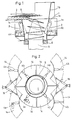
- die Vorrichtung von der Seite gesehen im Radialschnitt,
- Fig. 2
- die Draufsicht auf Fig. 1,
- Fig. 3
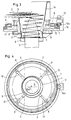
- eine andere Ausbildungsform der Vorrichtung ebenfalls im Radialschnitt,
- Fig. 4
- die Draufsicht auf Fig. 3 und
- Fig. 5
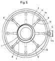
- eine andere Ausbildungsform der Vorrichtung in der Draufsicht entsprechend Fig. 4
- Fig. 1
- the device seen from the side in radial section,
- Fig. 2
- the top view of Fig. 1,
- Fig. 3
- another embodiment of the device also in radial section,
- Fig. 4
- the top view of Fig. 3 and
- Fig. 5
- another embodiment of the device in plan view corresponding to FIG. 4
Wie aus Fig. 1 und 2 zu ersehen, ist über der Bundbildekammer 1 mit
deren Traggehäuse 1a der Einlaufteil 1b angeordnet, in den der
Förderer 2 mit den darauf liegenden Walzdrahtwindungen S hineinragt.
Unterhalb der Bundbildekammer 1 befindet sich die, hier ringförmige
Bundtragplatte 6, die den, in die Bundbildekammer 1 ragenden Sammeldorn
5 einfaßt. Die Windungen S fallen in der dargestellten Weise
in die Bundbildekammer 1, und der dabei gebildete Bund liegt auf
der Bundtragplatte 6 auf. Im Traggehäuse 1a sind am Außenumfang der
Bundbildekammer 1 die Schwenklaschen 3 angelenkt, an deren Rückseite
Schubantriebsaggregate angreifen, die hier einmal als Exzentermotor
4a und einmal druckmittelbeaufschlagtes Kolbenzylinderaggregat bzw.
als Elektromagnet ausgebildet sind. Die Schwenklaschen 3 werden mit
Hilfe dieser Schubantriebsaggregate 4a bzw. 4b durch Längsschlitze
1c in der Wandung der Bundbildekammer 1 in den Innenraum dieser
Kammer hinein und wieder herausgeschwenkt. Diese Schwenkbewegungen
werden mit Hilfe einer, nicht dargestellten Folgesteuereinrichtung
für die Schubantriebsaggregate 4a, 4b so in die Bundbildekammer 1
hinein- und herausbewegt, wie dies in Fig. 2 angedeutet ist, d. h.
so, daß die Windungen S im Umlaufsinne eines Exzenterkreises zur
Mittenachse der Bundbildekammer 1 beaufschlagt werden.As can be seen from FIGS. 1 and 2, is above the
Die Schwenklaschen 3 sind mit ihren Schubantriebsaggregaten 4a bzw.
4b, wie in unterbrochenen Linien in Fig. 2 angedeutet, auf Segmenttragplatten
14 angeordnet, die mit Hilfe von druckmittelbeaufschlagten
Kolbenzylinderaggregaten 15 aus dem Traggehäuse 1 herausgeschwenkt
werden können, um z. B. die Bundbildekammer 1 für das
seitliche Herausfahren des Sammeldorns 5 mit dem Bund oder das
Herausheben des Bundes bei Betriebsstörungen bzw. für Montage- oder
Reparaturarbeiten frei zu machen. Dabei besteht die Möglichkeit,
diesen Vorgang durch entsprechende Sicherheits-Schaltelemente
automatisch auszulösen.The
Bei der Ausbildung nach Fig. 3 werden die Schwenklaschen 3 durch
einen, im Tragegehäuse 1a gelagerten, durch einen Motor 12 über ein
Zahnritzel 12a umlaufend angetriebenen Exzenterring 7 (vgl. auch
Fig. 4) über in Übertragungsgestängen 13 gelagerte Rollen 8 gegen
die Wirkung von Rückzugfedern 9 betätigt.3, the
Bei der Ausbildung nach Fig. 5 ist anstelle des Exzenterrings bei
der Ausbildung nach Fig. 3 und 4 ein Umlaufring 11 mit einer nach
innen vorspringenden Nockenfläche 10 vorgesehen, die hier als Schubantriebsaggregat
wirksam wird mit der Folge, daß z. B. bei der
dargestellten Verwendung von vier Schwenklaschen in der, strichpunktiert
angedeuteten Drehlage alle Schwenklaschen 3 sich außerhalb
des Innenraums der Bundbildekammer 1 befinden. 5 is in place of the
- 11
- BundbildekammerBundbildekammer
- 1a1a
- (trichterförmiger) Einlaufteil(funnel-shaped) inlet part
- 1b1b
- TraggehäuseSupport housing
- 1c1c
- LängsschlitzLongitudinal slot
- 22nd
- FördererSponsor
- 33rd
- SchwenklascheSwivel tab
- 44th
- --
- 4a4a
- Exzentereccentric
- 4b4b
- KolbenzylinderaggregatPiston cylinder unit
- 55
- SammeldornMandrel
- 66
- BundtragplatteCollar support plate
- 77
- ExzenterringEccentric ring
- 88th
- Rollenroll
- 99
- RückzugfederReturn spring
- 1010th
- NockenflächeCam surface
- 1111
- Ringring
- 1212th
- Motorengine
- 12a12a
- ZahnritzelPinion
- 1313
- ÜbertragungsgestängeTransmission linkage
- 1414
- SegmenttragplatteSegment support plate
- 1515
- KolbenzylinderaggregatPiston cylinder unit
- SS
- WalzdrahtwindungWire rod winding
Claims (10)
dadurch gekennzeichnet,
daß die Querverschiebeeinrichtungen aus, außerhalb der Bundbildekammer (1) hängend gelagerten Schwenklaschen (3) bestehen, die, durch senkrechte Schlitzausnehmungen (1a) in der Zylinderwand der Bundbildekammer (1) in deren Innenraum ein- und herausschwenkbar sind.Device for guiding and transversely displacing rolled wire windings, which are transported in an approximately horizontal position by means of a conveyor and are thrown off into an upright cylindrical bundle forming chamber to form wire bundles, with transverse displacement devices which can be inserted and removed in the region of the interior of the bundle former chamber, which act on the rolled wire windings,
characterized,
that the transverse shifting devices consist of pivoting brackets (3) which are mounted in a hanging manner outside the bundle forming chamber (1) and which can be pivoted in and out of the interior of the bundle forming chamber (1) by vertical slot recesses (1a) in the cylinder wall.
gekennzeichnet durch
außerhalb des Innenraums der Bundbildekammer (1) angeordnete, mit den Schwenklaschen (3) verbundene, gemeinsam oder unabhängig voneinander betätigbare Schubantriebaggregate (4a, 4b, 7, 11).Device according to claim 1,
marked by
thrust drive units (4a, 4b, 7, 11) which are arranged outside the interior of the bundle forming chamber (1) and are connected to the swivel tabs (3) and can be actuated jointly or independently of one another.
dadurch gekennzeichnet,
dass die Schubantriebsaggregate (4a, 4b) hydraulisch, pneumatisch oder elektromagnetisch angetrieben sind. Device according to claim 2,
characterized,
that the thrust drive units (4a, 4b) are hydraulically, pneumatically or electromagnetically driven.
dadurch gekennzeichnet,
dass die Schubantriebsaggregate als, die Schwenklaschen (3) rückseitig beaufschlagende Nockenringe (4a, 10, 11) ausgebildet sind.Device according to claim 2,
characterized,
that the thrust drive units are designed as cam rings (4a, 10, 11) acting on the swivel tabs (3) on the rear.
gekennzeichnet durch
einen, die Bundbildekammer (1) mit radialem Abstand umfassenden, drehbar gelagerten, Exzenter- oder Nockenring als Schubantriebsaggregat für die Schwenklaschen (3).Device according to claim 2,
marked by
one, the bundle forming chamber (1) with a radial distance, rotatably mounted, eccentric or cam ring as a thrust drive unit for the swivel tabs (3).
gekennzeichnet durch
eine Einzel-, Folge- oder Gruppensteuerung für die Schubantriebsaggregate.Device according to one or more of claims 2 to 4,
marked by
a single, sequential or group control for the thrust drive units.
dadurch gekennzeichnet,
daß die Schwenklaschen (3) mit leichtem Spiel in die Schlitzausnehmungen (1c) der Bundbildekammer (1) eingepaßt sind.Device according to one or more of claims 1 to 6,
characterized,
that the swivel tabs (3) with a slight play in the slot recesses (1c) of the bundle chamber (1) are fitted.
dadurch gekennzeichnet,
daß die die Walzdrahtwindungen (S) beaufschlagenden Flächenabschnitte der Schwenklaschen (3) eben oder quer zu deren Längsrichtung leicht gewölbt verlaufen.Device according to one or more of claims 1 to 7,
characterized,
that the surface sections of the swivel brackets (3) which act on the rolled wire windings (S) are slightly arched flat or transversely to their longitudinal direction.
dadurch gekennzeichnet,
daß die Schwenklaschen (3) gehärtete und/oder gleitfördernde Beschichtungen aufweisen. Device according to one or more of claims 1 to 8,
characterized,
that the swivel tabs (3) have hardened and / or slide-promoting coatings.
gekennzeichnet durch
eine gegeneinander höhenversetzte Anordnung der Hängelager der Schwenklaschen 3.Device according to claim 1,
marked by
a mutually vertically offset arrangement of the hanging bearings of the swivel tabs 3.
Applications Claiming Priority (2)
| Application Number | Priority Date | Filing Date | Title |
|---|---|---|---|
| DE19811649A DE19811649A1 (en) | 1998-03-18 | 1998-03-18 | Device for guiding and transverse displacement of rolled wire twists |
| DE19811649 | 1998-03-18 |
Publications (2)
| Publication Number | Publication Date |
|---|---|
| EP0943378A2 true EP0943378A2 (en) | 1999-09-22 |
| EP0943378A3 EP0943378A3 (en) | 2001-04-25 |
Family
ID=7861246
Family Applications (1)
| Application Number | Title | Priority Date | Filing Date |
|---|---|---|---|
| EP99104713A Withdrawn EP0943378A3 (en) | 1998-03-18 | 1999-03-10 | Device for the feeding and lateral displacement of rolled wire loops |
Country Status (4)
| Country | Link |
|---|---|
| US (1) | US6158683A (en) |
| EP (1) | EP0943378A3 (en) |
| JP (1) | JPH11319930A (en) |
| DE (1) | DE19811649A1 (en) |
Families Citing this family (6)
| Publication number | Priority date | Publication date | Assignee | Title |
|---|---|---|---|---|
| SE514295C2 (en) * | 1999-05-03 | 2001-02-05 | Skaltek Ab | Method and apparatus for rolling a cable, cable, cable or the like to a ring |
| DE10026583A1 (en) * | 2000-05-30 | 2001-12-13 | Sket Walzwerkstechnik Gmbh | Device to form wire windings into wire coil; has coil separator with evenly spaced centring flaps to centre wire windings, which are moved tranversely and stacked in vertical collection shaft |
| DE10052731A1 (en) * | 2000-10-25 | 2002-05-02 | Sms Demag Ag | Device for influencing the drop position of rolled wire windings thrown into a bundle shaft |
| US9162269B2 (en) * | 2012-11-29 | 2015-10-20 | Primetals Technologies USA LLC | Coil forming apparatus and method |
| CN104759473A (en) * | 2014-01-07 | 2015-07-08 | 安阳合力创科冶金新技术研发股份有限公司 | Interactive wire distributor |
| EP3260212B1 (en) | 2016-06-20 | 2019-05-15 | Sund Birsta AB | Coil-forming machine |
Citations (4)
| Publication number | Priority date | Publication date | Assignee | Title |
|---|---|---|---|---|
| US4357965A (en) * | 1979-04-13 | 1982-11-09 | Nippon Steel Corporation | Method and apparatus for gathering a ring shaped wire rod |
| JPH05329538A (en) * | 1991-04-22 | 1993-12-14 | Sumitomo Heavy Ind Ltd | Loose winding device in wire rod bundling device |
| JPH09285818A (en) * | 1996-04-25 | 1997-11-04 | Sumitomo Heavy Ind Ltd | Wire coil bundling device |
| JPH10166050A (en) * | 1996-12-02 | 1998-06-23 | Sumitomo Metal Ind Ltd | Reforming device of wire coil |
Family Cites Families (12)
| Publication number | Priority date | Publication date | Assignee | Title |
|---|---|---|---|---|
| US35440A (en) * | 1862-06-03 | Improvement in heaters | ||
| BR7601196A (en) * | 1975-03-07 | 1976-09-14 | Barmag Barmer Maschf | TRANSPORTATION DEVICE FOR SYNTHETIC FIBER CABLE AND THE PROCESS OF ITS OPERATION |
| DE2747706C3 (en) * | 1977-10-25 | 1986-06-19 | Officine Savio S.p.A., Pordenone | Device for depositing a cable consisting of a plurality of threads, in particular a cable made of man-made fibers or the like. in a jug |
| US4376517A (en) * | 1980-04-16 | 1983-03-15 | Barmag Barmer Maschinenfabrik Ag | Method and apparatus for depositing yarn |
| DE3117181A1 (en) * | 1981-04-30 | 1982-11-25 | SMS Schloemann-Siemag AG, 4000 Düsseldorf | Apparatus for severing a wire-turn strand in a bundle-forming station |
| DD253384B3 (en) * | 1986-10-22 | 1993-01-07 | Thaelmann Schwermaschbau Veb | DEVICE FOR FORMING ROLLED WIRE AND SCRAP CONTAINERS |
| US5273231A (en) * | 1992-08-03 | 1993-12-28 | Morgan Construction Company | Loop distributor for reforming station |
| IT1267252B1 (en) * | 1994-06-07 | 1997-01-28 | Danieli Off Mecc | DEVICE FOR THE ASYMMETRICAL DEPOSIT OF THE COILS |
| IT1267251B1 (en) * | 1994-06-07 | 1997-01-28 | Danieli Off Mecc | DEVICE FOR THE ASYMMETRICAL DEPOSIT OF THE COILS |
| US5779174A (en) * | 1996-04-02 | 1998-07-14 | Morgan Construction Company | Mounting arrangement for loop distributor in a reforming chamber |
| DE19704421B4 (en) * | 1997-02-06 | 2008-04-10 | Sms Demag Ag | Apparatus for forming coils of wire rod loops |
| US6073873A (en) * | 1997-11-14 | 2000-06-13 | Morgan Construction Company | Coil forming apparatus and method |
-
1998
- 1998-03-18 DE DE19811649A patent/DE19811649A1/en not_active Withdrawn
-
1999
- 1999-03-10 EP EP99104713A patent/EP0943378A3/en not_active Withdrawn
- 1999-03-16 JP JP11070867A patent/JPH11319930A/en not_active Withdrawn
- 1999-03-16 US US09/270,393 patent/US6158683A/en not_active Expired - Fee Related
Patent Citations (4)
| Publication number | Priority date | Publication date | Assignee | Title |
|---|---|---|---|---|
| US4357965A (en) * | 1979-04-13 | 1982-11-09 | Nippon Steel Corporation | Method and apparatus for gathering a ring shaped wire rod |
| JPH05329538A (en) * | 1991-04-22 | 1993-12-14 | Sumitomo Heavy Ind Ltd | Loose winding device in wire rod bundling device |
| JPH09285818A (en) * | 1996-04-25 | 1997-11-04 | Sumitomo Heavy Ind Ltd | Wire coil bundling device |
| JPH10166050A (en) * | 1996-12-02 | 1998-06-23 | Sumitomo Metal Ind Ltd | Reforming device of wire coil |
Non-Patent Citations (3)
| Title |
|---|
| PATENT ABSTRACTS OF JAPAN vol. 018, no. 151 (M-1576), 14. März 1994 (1994-03-14) & JP 05 329538 A (SUMITOMO HEAVY IND LTD), 14. Dezember 1993 (1993-12-14) * |
| PATENT ABSTRACTS OF JAPAN vol. 1998, no. 03, 27. Februar 1998 (1998-02-27) & JP 09 285818 A (SUMITOMO HEAVY IND LTD;KOBE STEEL LTD), 4. November 1997 (1997-11-04) * |
| PATENT ABSTRACTS OF JAPAN vol. 1998, no. 11, 30. September 1998 (1998-09-30) & JP 10 166050 A (SUMITOMO METAL IND LTD), 23. Juni 1998 (1998-06-23) * |
Also Published As
| Publication number | Publication date |
|---|---|
| DE19811649A1 (en) | 1999-09-23 |
| EP0943378A3 (en) | 2001-04-25 |
| JPH11319930A (en) | 1999-11-24 |
| US6158683A (en) | 2000-12-12 |
Similar Documents
| Publication | Publication Date | Title |
|---|---|---|
| EP0774214A2 (en) | Apparatus for feeding cigarettes | |
| EP0149058B1 (en) | Apparatus for feeding printing products to a continuous-production line and method to operate the same | |
| DE2262148A1 (en) | METHOD AND DEVICE FOR INTERMEDIATE STORAGE OF TAPE-SHAPED MATERIALS, IN PARTICULAR METAL TAPE, IN CONTINUOUS TAPE FEEDS TO PROCESSING MACHINES | |
| DE3221324A1 (en) | DEVICE FOR PALLETIZING PARTS | |
| EP0229888B1 (en) | Device for stocking printed products advancing in an overlapping fashion | |
| EP0943378A2 (en) | Device for the feeding and lateral displacement of rolled wire loops | |
| DE4425079A1 (en) | Device for loading bobbins in a packaging machine | |
| EP0566910B1 (en) | Device for transporting rolled stock wound in rings in the coiling area | |
| EP0569719B1 (en) | Band transport system | |
| DE1761434A1 (en) | Device for collecting, binding and transporting wire or strip-shaped rolled material | |
| EP0607891B1 (en) | Device for shrinking, stretching, drying, finishing, dyeing, feeding or or the like a moving textile material as band or yarn | |
| DE2905537C2 (en) | ||
| EP0979689B1 (en) | Device for minimising the height of wire bundles in a coiling chamber | |
| DE3424439C2 (en) | ||
| EP1175945B1 (en) | Coil forming had with laying tube for rolled wire | |
| DE2917027A1 (en) | METHOD AND DEVICE FOR PROMOTING SUCCESSIVE HOT WINDINGS | |
| DE60109323T2 (en) | DEVICE AND METHOD FOR WRAPPING TRACKS | |
| DE3717295C2 (en) | ||
| EP0419447A1 (en) | Method and device for descaling of round steel bars | |
| EP2511207B1 (en) | Device for intermediate storage of flat products, in particular printed products, which can be coiled in a scale assembly, and method for operating such a device | |
| DE19704421B4 (en) | Apparatus for forming coils of wire rod loops | |
| DE2731559A1 (en) | Steel angle stacking machine - has grab magnets and transporters travelling in opposite directions where they overlap | |
| DE3610138C2 (en) | ||
| EP0982248A1 (en) | Conveyor device for a packaging machine | |
| DE4304734C2 (en) | Device for separating and pivoting narrow band bundles |
Legal Events
| Date | Code | Title | Description |
|---|---|---|---|
| PUAI | Public reference made under article 153(3) epc to a published international application that has entered the european phase |
Free format text: ORIGINAL CODE: 0009012 |
|
| 17P | Request for examination filed |
Effective date: 19990326 |
|
| AK | Designated contracting states |
Kind code of ref document: A2 Designated state(s): AT DE GB IT SE |
|
| AX | Request for extension of the european patent |
Free format text: AL;LT;LV;MK;RO;SI |
|
| RAP1 | Party data changed (applicant data changed or rights of an application transferred) |
Owner name: SMS DEMAG AG |
|
| PUAL | Search report despatched |
Free format text: ORIGINAL CODE: 0009013 |
|
| AK | Designated contracting states |
Kind code of ref document: A3 Designated state(s): AT BE CH CY DE DK ES FI FR GB GR IE IT LI LU MC NL PT SE |
|
| AX | Request for extension of the european patent |
Free format text: AL;LT;LV;MK;RO;SI |
|
| AKX | Designation fees paid |
Free format text: AT DE GB IT SE |
|
| 17Q | First examination report despatched |
Effective date: 20030425 |
|
| STAA | Information on the status of an ep patent application or granted ep patent |
Free format text: STATUS: THE APPLICATION IS DEEMED TO BE WITHDRAWN |
|
| 18D | Application deemed to be withdrawn |
Effective date: 20030906 |