EP0942872B1 - Verahren und einrichtung zum verbinden von abstandhaltern - Google Patents
Verahren und einrichtung zum verbinden von abstandhaltern Download PDFInfo
- Publication number
- EP0942872B1 EP0942872B1 EP97947245A EP97947245A EP0942872B1 EP 0942872 B1 EP0942872 B1 EP 0942872B1 EP 97947245 A EP97947245 A EP 97947245A EP 97947245 A EP97947245 A EP 97947245A EP 0942872 B1 EP0942872 B1 EP 0942872B1
- Authority
- EP
- European Patent Office
- Prior art keywords
- spacers
- pallets
- band
- joining
- strapping
- Prior art date
- Legal status (The legal status is an assumption and is not a legal conclusion. Google has not performed a legal analysis and makes no representation as to the accuracy of the status listed.)
- Expired - Lifetime
Links
- 125000006850 spacer group Chemical group 0.000 title claims abstract description 66
- 238000000034 method Methods 0.000 title claims abstract description 25
- 238000005304 joining Methods 0.000 claims abstract description 60
- 229910000831 Steel Inorganic materials 0.000 claims description 11
- 239000010959 steel Substances 0.000 claims description 11
- 238000003466 welding Methods 0.000 claims description 4
- 230000006835 compression Effects 0.000 claims 1
- 238000007906 compression Methods 0.000 claims 1
- 239000000969 carrier Substances 0.000 abstract description 3
- 230000032258 transport Effects 0.000 description 14
- 238000009826 distribution Methods 0.000 description 5
- 239000000463 material Substances 0.000 description 5
- 230000008878 coupling Effects 0.000 description 4
- 238000010168 coupling process Methods 0.000 description 4
- 238000005859 coupling reaction Methods 0.000 description 4
- 238000004519 manufacturing process Methods 0.000 description 4
- 230000008901 benefit Effects 0.000 description 3
- 238000010276 construction Methods 0.000 description 3
- 230000003028 elevating effect Effects 0.000 description 2
- 230000001747 exhibiting effect Effects 0.000 description 2
- 229910052751 metal Inorganic materials 0.000 description 2
- 239000002184 metal Substances 0.000 description 2
- 230000002787 reinforcement Effects 0.000 description 2
- 230000000087 stabilizing effect Effects 0.000 description 2
- 238000003860 storage Methods 0.000 description 2
- 239000002023 wood Substances 0.000 description 2
- 229910001335 Galvanized steel Inorganic materials 0.000 description 1
- 239000004411 aluminium Substances 0.000 description 1
- 229910052782 aluminium Inorganic materials 0.000 description 1
- XAGFODPZIPBFFR-UHFFFAOYSA-N aluminium Chemical compound [Al] XAGFODPZIPBFFR-UHFFFAOYSA-N 0.000 description 1
- 238000005520 cutting process Methods 0.000 description 1
- 230000003203 everyday effect Effects 0.000 description 1
- 239000000835 fiber Substances 0.000 description 1
- 239000008397 galvanized steel Substances 0.000 description 1
- 230000007246 mechanism Effects 0.000 description 1
- 238000004806 packaging method and process Methods 0.000 description 1
- 238000012856 packing Methods 0.000 description 1
- 238000004064 recycling Methods 0.000 description 1
- 238000000926 separation method Methods 0.000 description 1
- 230000007704 transition Effects 0.000 description 1
- 230000007306 turnover Effects 0.000 description 1
Images


Classifications
-
- B—PERFORMING OPERATIONS; TRANSPORTING
- B65—CONVEYING; PACKING; STORING; HANDLING THIN OR FILAMENTARY MATERIAL
- B65D—CONTAINERS FOR STORAGE OR TRANSPORT OF ARTICLES OR MATERIALS, e.g. BAGS, BARRELS, BOTTLES, BOXES, CANS, CARTONS, CRATES, DRUMS, JARS, TANKS, HOPPERS, FORWARDING CONTAINERS; ACCESSORIES, CLOSURES, OR FITTINGS THEREFOR; PACKAGING ELEMENTS; PACKAGES
- B65D19/00—Pallets or like platforms, with or without side walls, for supporting loads to be lifted or lowered
- B65D19/0004—Rigid pallets without side walls
- B65D19/0053—Rigid pallets without side walls the load supporting surface being made of more than one element
- B65D19/0077—Rigid pallets without side walls the load supporting surface being made of more than one element forming discontinuous or non-planar contact surfaces
- B65D19/0089—Rigid pallets without side walls the load supporting surface being made of more than one element forming discontinuous or non-planar contact surfaces the base surface being made of more than one element
- B65D19/0093—Rigid pallets without side walls the load supporting surface being made of more than one element forming discontinuous or non-planar contact surfaces the base surface being made of more than one element forming discontinuous or non-planar contact surfaces
- B65D19/0095—Rigid pallets without side walls the load supporting surface being made of more than one element forming discontinuous or non-planar contact surfaces the base surface being made of more than one element forming discontinuous or non-planar contact surfaces and each contact surface having a stringer-like shape
-
- B—PERFORMING OPERATIONS; TRANSPORTING
- B65—CONVEYING; PACKING; STORING; HANDLING THIN OR FILAMENTARY MATERIAL
- B65D—CONTAINERS FOR STORAGE OR TRANSPORT OF ARTICLES OR MATERIALS, e.g. BAGS, BARRELS, BOTTLES, BOXES, CANS, CARTONS, CRATES, DRUMS, JARS, TANKS, HOPPERS, FORWARDING CONTAINERS; ACCESSORIES, CLOSURES, OR FITTINGS THEREFOR; PACKAGING ELEMENTS; PACKAGES
- B65D2519/00—Pallets or like platforms, with or without side walls, for supporting loads to be lifted or lowered
- B65D2519/00004—Details relating to pallets
- B65D2519/00258—Overall construction
- B65D2519/00263—Overall construction of the pallet
- B65D2519/00273—Overall construction of the pallet made of more than one piece
-
- B—PERFORMING OPERATIONS; TRANSPORTING
- B65—CONVEYING; PACKING; STORING; HANDLING THIN OR FILAMENTARY MATERIAL
- B65D—CONTAINERS FOR STORAGE OR TRANSPORT OF ARTICLES OR MATERIALS, e.g. BAGS, BARRELS, BOTTLES, BOXES, CANS, CARTONS, CRATES, DRUMS, JARS, TANKS, HOPPERS, FORWARDING CONTAINERS; ACCESSORIES, CLOSURES, OR FITTINGS THEREFOR; PACKAGING ELEMENTS; PACKAGES
- B65D2519/00—Pallets or like platforms, with or without side walls, for supporting loads to be lifted or lowered
- B65D2519/00004—Details relating to pallets
- B65D2519/00258—Overall construction
- B65D2519/00283—Overall construction of the load supporting surface
- B65D2519/00288—Overall construction of the load supporting surface made of one piece
-
- B—PERFORMING OPERATIONS; TRANSPORTING
- B65—CONVEYING; PACKING; STORING; HANDLING THIN OR FILAMENTARY MATERIAL
- B65D—CONTAINERS FOR STORAGE OR TRANSPORT OF ARTICLES OR MATERIALS, e.g. BAGS, BARRELS, BOTTLES, BOXES, CANS, CARTONS, CRATES, DRUMS, JARS, TANKS, HOPPERS, FORWARDING CONTAINERS; ACCESSORIES, CLOSURES, OR FITTINGS THEREFOR; PACKAGING ELEMENTS; PACKAGES
- B65D2519/00—Pallets or like platforms, with or without side walls, for supporting loads to be lifted or lowered
- B65D2519/00004—Details relating to pallets
- B65D2519/00258—Overall construction
- B65D2519/00283—Overall construction of the load supporting surface
- B65D2519/00293—Overall construction of the load supporting surface made of more than one piece
-
- B—PERFORMING OPERATIONS; TRANSPORTING
- B65—CONVEYING; PACKING; STORING; HANDLING THIN OR FILAMENTARY MATERIAL
- B65D—CONTAINERS FOR STORAGE OR TRANSPORT OF ARTICLES OR MATERIALS, e.g. BAGS, BARRELS, BOTTLES, BOXES, CANS, CARTONS, CRATES, DRUMS, JARS, TANKS, HOPPERS, FORWARDING CONTAINERS; ACCESSORIES, CLOSURES, OR FITTINGS THEREFOR; PACKAGING ELEMENTS; PACKAGES
- B65D2519/00—Pallets or like platforms, with or without side walls, for supporting loads to be lifted or lowered
- B65D2519/00004—Details relating to pallets
- B65D2519/00258—Overall construction
- B65D2519/00313—Overall construction of the base surface
- B65D2519/00323—Overall construction of the base surface made of more than one piece
-
- B—PERFORMING OPERATIONS; TRANSPORTING
- B65—CONVEYING; PACKING; STORING; HANDLING THIN OR FILAMENTARY MATERIAL
- B65D—CONTAINERS FOR STORAGE OR TRANSPORT OF ARTICLES OR MATERIALS, e.g. BAGS, BARRELS, BOTTLES, BOXES, CANS, CARTONS, CRATES, DRUMS, JARS, TANKS, HOPPERS, FORWARDING CONTAINERS; ACCESSORIES, CLOSURES, OR FITTINGS THEREFOR; PACKAGING ELEMENTS; PACKAGES
- B65D2519/00—Pallets or like platforms, with or without side walls, for supporting loads to be lifted or lowered
- B65D2519/00004—Details relating to pallets
- B65D2519/00258—Overall construction
- B65D2519/00313—Overall construction of the base surface
- B65D2519/00328—Overall construction of the base surface shape of the contact surface of the base
- B65D2519/00333—Overall construction of the base surface shape of the contact surface of the base contact surface having a stringer-like shape
-
- B—PERFORMING OPERATIONS; TRANSPORTING
- B65—CONVEYING; PACKING; STORING; HANDLING THIN OR FILAMENTARY MATERIAL
- B65D—CONTAINERS FOR STORAGE OR TRANSPORT OF ARTICLES OR MATERIALS, e.g. BAGS, BARRELS, BOTTLES, BOXES, CANS, CARTONS, CRATES, DRUMS, JARS, TANKS, HOPPERS, FORWARDING CONTAINERS; ACCESSORIES, CLOSURES, OR FITTINGS THEREFOR; PACKAGING ELEMENTS; PACKAGES
- B65D2519/00—Pallets or like platforms, with or without side walls, for supporting loads to be lifted or lowered
- B65D2519/00004—Details relating to pallets
- B65D2519/00258—Overall construction
- B65D2519/00368—Overall construction of the non-integral separating spacer
- B65D2519/00373—Overall construction of the non-integral separating spacer whereby at least one spacer is made of one piece
-
- B—PERFORMING OPERATIONS; TRANSPORTING
- B65—CONVEYING; PACKING; STORING; HANDLING THIN OR FILAMENTARY MATERIAL
- B65D—CONTAINERS FOR STORAGE OR TRANSPORT OF ARTICLES OR MATERIALS, e.g. BAGS, BARRELS, BOTTLES, BOXES, CANS, CARTONS, CRATES, DRUMS, JARS, TANKS, HOPPERS, FORWARDING CONTAINERS; ACCESSORIES, CLOSURES, OR FITTINGS THEREFOR; PACKAGING ELEMENTS; PACKAGES
- B65D2519/00—Pallets or like platforms, with or without side walls, for supporting loads to be lifted or lowered
- B65D2519/00004—Details relating to pallets
- B65D2519/00547—Connections
- B65D2519/00552—Structures connecting the constitutive elements of the pallet to each other, i.e. load supporting surface, base surface and/or separate spacer
- B65D2519/00572—Structures connecting the constitutive elements of the pallet to each other, i.e. load supporting surface, base surface and/or separate spacer with separate auxiliary element, e.g. screws, nails, bayonets
-
- B—PERFORMING OPERATIONS; TRANSPORTING
- B65—CONVEYING; PACKING; STORING; HANDLING THIN OR FILAMENTARY MATERIAL
- B65D—CONTAINERS FOR STORAGE OR TRANSPORT OF ARTICLES OR MATERIALS, e.g. BAGS, BARRELS, BOTTLES, BOXES, CANS, CARTONS, CRATES, DRUMS, JARS, TANKS, HOPPERS, FORWARDING CONTAINERS; ACCESSORIES, CLOSURES, OR FITTINGS THEREFOR; PACKAGING ELEMENTS; PACKAGES
- B65D2519/00—Pallets or like platforms, with or without side walls, for supporting loads to be lifted or lowered
- B65D2519/00004—Details relating to pallets
- B65D2519/00736—Details
- B65D2519/00741—Dimensional aspects of the pallet
- B65D2519/00746—Dimensional aspects of the pallet divisible into sub-pallets of smaller dimensions
- B65D2519/00756—Dimensional aspects of the pallet divisible into sub-pallets of smaller dimensions joined together by removable elements, e.g. bands encircling the feed
-
- Y—GENERAL TAGGING OF NEW TECHNOLOGICAL DEVELOPMENTS; GENERAL TAGGING OF CROSS-SECTIONAL TECHNOLOGIES SPANNING OVER SEVERAL SECTIONS OF THE IPC; TECHNICAL SUBJECTS COVERED BY FORMER USPC CROSS-REFERENCE ART COLLECTIONS [XRACs] AND DIGESTS
- Y10—TECHNICAL SUBJECTS COVERED BY FORMER USPC
- Y10S—TECHNICAL SUBJECTS COVERED BY FORMER USPC CROSS-REFERENCE ART COLLECTIONS [XRACs] AND DIGESTS
- Y10S108/00—Horizontally supported planar surfaces
- Y10S108/901—Synthetic plastic industrial platform, e.g. pallet
-
- Y—GENERAL TAGGING OF NEW TECHNOLOGICAL DEVELOPMENTS; GENERAL TAGGING OF CROSS-SECTIONAL TECHNOLOGIES SPANNING OVER SEVERAL SECTIONS OF THE IPC; TECHNICAL SUBJECTS COVERED BY FORMER USPC CROSS-REFERENCE ART COLLECTIONS [XRACs] AND DIGESTS
- Y10—TECHNICAL SUBJECTS COVERED BY FORMER USPC
- Y10T—TECHNICAL SUBJECTS COVERED BY FORMER US CLASSIFICATION
- Y10T24/00—Buckles, buttons, clasps, etc.
- Y10T24/29—Drum or can spacer fastener
-
- Y—GENERAL TAGGING OF NEW TECHNOLOGICAL DEVELOPMENTS; GENERAL TAGGING OF CROSS-SECTIONAL TECHNOLOGIES SPANNING OVER SEVERAL SECTIONS OF THE IPC; TECHNICAL SUBJECTS COVERED BY FORMER USPC CROSS-REFERENCE ART COLLECTIONS [XRACs] AND DIGESTS
- Y10—TECHNICAL SUBJECTS COVERED BY FORMER USPC
- Y10T—TECHNICAL SUBJECTS COVERED BY FORMER US CLASSIFICATION
- Y10T29/00—Metal working
- Y10T29/49—Method of mechanical manufacture
- Y10T29/49826—Assembling or joining
- Y10T29/49828—Progressively advancing of work assembly station or assembled portion of work
- Y10T29/49829—Advancing work to successive stations [i.e., assembly line]
Definitions
- the present invention relates to a method for providing detachable joining together of spacers in pairs, formed by support blocks for pallets or support walls in pallets by joining together said spacers by means of flexible straps.
- slave pallets 800 x 1200 full size pallets
- a return system of pallets which are joined together sideways for forming larger pallets or other load carriers e.g. of plastic material requires rational joining methods and handling of pallets and/or therein included parts.
- the main object of the present invention is therefore in the first hand to find a method which solves among other said problem efficiently and safely and which enables automatizing joining together part pallets or spacers for these.
- a hauling track conveys spacers, compressed in pairs to a station for joining, that the pairs of spacers are encompassed by means of a ring shaped preferably openable band guide along which said band is arranged to run until it forms a loop around the spacer, wherein they are joined together and clamped together tightly, and allowing a band encompass and run around said pair of spacers in the manner of a sling in a strapping machine, which is located beside a conveyor line for at least spacers, before the following connecting of the band ends with each other for forming a divisible joining sling which encloses said spacers in pairs.
- Another object of the present invention is to provide a machine for performing a method for detachable joining together of spacers in pairs, preferably formed by support blocks for pallets or support walls in pallets by joining together said spacers by means of flexible straps.
- a machine which is substantially characterized in that it includes a hauling track for conveying spacers to a joining station along the hauling track for the spacers as well as a ring shaped preferably openable band guide, along which said band is arranged to run until it forms a sling around the spacer, and that the machine is arranged to function as an automatic machine for feeding spacers forward to a stop position and subsequent strapping by means of straps which are arranged to be fed continuously to a strapping machine located sideways displaced from said hauling track.
- the invention is strongly aimed at the future because the need for smaller pallet sizes is strongly growing. Thereby, e.g. also neighbourhood shops may get satisfactory turnover within a minimum of selling area. At the same time as wholesale trade may maintain an efficient form of distribution.
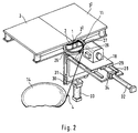
- a method for providing detachable joining by means of a detachable joint 1 of in pairs tightly held together spacers 2, 2 1 which preferably are formed by support blocks for pallets 3, 3 1 in pairs, or support walls in pallets or other load carriers, by joining aforementioned spacers 2, 2 1 , by means of flexible bands 4 or by means of other suitable detachable joining means for this purpose, an automated method.
- a hauling track 10 conveys aforementioned spacers 2, 2 1 sideways, which are unattached as is shown e.g. in fig. 1, or that already are integral building units or side walls of each divided pallet 3, 3 1 , or other load carrier e.g. platform, container, etc. to a joining station 5 packed together tightly in pairs at a common level 6. Then the aforementioned spacers 2, 2 1 , are joined together in pairs by means of suitable joining means 4 and are clamped together tightly.
- bands 4 as external joining means and which are in the manner of a sling brought to surround and enclose said pair of spacers 2, 2 1 , in a strapping machine 7, which is located at the side 8 of a feeding line 9 for at least spacers 2, 2 1 . Then follows mutual joining of band ends 4A, 4B, for forming a divisible strap 1 which encloses said spacers 2, 2 1 in pairs.
- the aforementioned pairs of spacers 2, 2 1 are enclosed by a ring shaped preferably openable band guide 11 along a substantially horizontal plane 12 and along which band guide 11 said band 4 is arranged to run until forming a sling around the spacer 2, 2 1 .
- the shown example relates to a method where band 4 consisting of metal is used and lead seals 13 or other coupling elements are used for threading onto the band 4 which is supplied continuously from a band magazine 14.
- spacers 2, 2 1 In order to provide efficient joining of spacers 2, 2 1 , with each other so that these which for example are formed by blocks of e.g. compressed fibre material with preferably circular cross section, do not risk gliding apart from each other or to be tilted due to incomplete joining with each other, is now suggested that you join the spacers 2, 2 1 , to each other at different levels 15, 15 1 . Therefore, the strapping station 5 is moved vertically with reference to the spacers 2,2 1 , between different levels 15, 15 1 , in order to be able to tighten the bands 4, 4 1 , on in pairs compressed spacers 2, 2 1 .
- these which for example are formed by blocks of e.g. compressed fibre material with preferably circular cross section
- the aforementioned strapping station 5 which includes a table 18 which may be elevated vertically 16 and sideways 17 perpendicular to the hauling track 10 displaceable, and which carries a said band guide device 11, is arranged to move between a retracted pass position I, shown in dashed lines in Fig 1, in order for the spacer 2, 2 1 , to be able to be received in it, and a forward moved strapping position II, shown with continuous lines in Fig 1, and respectively able to be elevated between at least two levels, in order to be able to insert the spacer 2, 2 1 , into the internal cavity 19 of the band guide device and to be able to locate the bands 4, 4 1 , at the desired level 15, 15 1 .
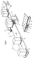
- a machine 20 for performing an above described method for strapping etc. of spacers 2, 2 1 , in pairs in accordance with the above, comprises a hauling track 10, e.g. a conveyor band 10A which runs between rollers 10B, 10C in pairs from a magazine 21 with loose spacers 2, 2 1 , 2 2 .... 2 n and to an outfeed station 22 via a joining station 23 between these along the hauling track 10 for the spacers 2-2 n .
- a hauling track 10 e.g. a conveyor band 10A which runs between rollers 10B, 10C in pairs from a magazine 21 with loose spacers 2, 2 1 , 2 2 .... 2 n and to an outfeed station 22 via a joining station 23 between these along the hauling track 10 for the spacers 2-2 n .
- the machine 20 is arranged to function as an automatic machine for both feeding the spacers 2-2 n forward to a stop position SL in front of the band guide device 11 and subsequent binding by means of bands 4, that are adapted to be fed forward continuously by means of drive means 24 for this purpose from a band roll 14, to a strapping machine 7 which is positioned sideways displaced from said hauling track 10.
- the band guide 11 which is designed as a combined band guide and strapping unit, is openable via a arched semi circle shaped aperture segment 25, which is articulated 26 connected to an also arched semi circle shaped frame segment 27, which may pivot around said joint 26 between a closed strapping position and an open position respectively, dash dotted line, for passing the spacer 2, 2 1 , through the band guide 11.
- the aforementioned binding unit 11 and the remaining parts of the strapping machine 7 are supported by a machine table 18, which is journalled via guideways 28, 29; 30, 31 sideways displaceable 17 actuated by a preferably hydraulic alternatively pneumatic cylinder or other jack 32, and elevating vertically 16 by means of a preferably hydraulic alternatively pneumatic cylinder or other kind of elevating jack 33, which supports a table frame 34 which may be angled between horizontal and vertical position.
- the hauling track may also be formed by for example a conveyor band adapted for receiving pallets 3, 3 1 , on it and which runs between a loading station for pallets 3, 3 1 , and an out feed member for banded pallets 3, 3 1 , or spacers 2, 2 1 , e.g. for joining quarto and/or semi pallets for forming a full pallet with interconnected spacers which abut each other.
- a conveyor band adapted for receiving pallets 3, 3 1 , on it and which runs between a loading station for pallets 3, 3 1 , and an out feed member for banded pallets 3, 3 1 , or spacers 2, 2 1 , e.g. for joining quarto and/or semi pallets for forming a full pallet with interconnected spacers which abut each other.
- an automatic machine for strapping by means of steel bands of spacers in form of pallet support blocks 2-2 n comprises the following parts and method described running:
- the pallet blocks 2-2 n are delivered stacked on a standard pallet with a rigid sheet between each layer (about 150 in each layer).
- the machine automatically feeds pallet blocks 2-2 n in pairs to the strapping station and further to transport wrapping alternatively that stacking on pallet is performed manually.
- the cycle is repeated until its pallet blocks are used up at the store, whereupon this sheet is lifted away and the lifting table is elevated to another level.
- Fig 4 and 4A two interconnected pallets 3, 3 1 , which exhibit coupling aids consisting of male and female e.g. dowel-hole 37, 38 or strip-aperture 39, 40 respectively which cooperate in pairs with each other along adjacent and interconnected pallet sides 3A, 3B.
- Said coupling means among other functions as stabilizing aids in connected position.
- the spacer may be provided with similar aids for stabilizing in both the vertical as well as the horizontal direction.
- the machine system in accordance with the invention is flexible adapted for joining return pallets and disposable pallets.
- Disposable pallets are Disposable pallets:.
- the joining machines are located at both sides of the machine line simultaneously perform the steps of joining.
- the joining may be made with different alternative methods:
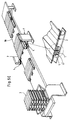
- fig 5 is shown two with goods 41 provided half pallets 3, 3 1 , which are on the way to the strapping machine 7.
- the first part pallet 3 1 has reached the machine 7 it stops, for example by lifting by means of not shown holding means a small distance above the means of transport 10.
- the transport means 10 and the first part pallet are lowered down to the transport means 10.
- the first part pallet 3 1 is allowed to slip on the transport means 10 until the other part pallet 3 has reached the first. Additional ways are naturally possible, especially feeding of semi pallets onto the transport means 10 in the form of intended units, which then are stopped at the joining station.
- the strapping machine 7 is activated, one at each side of the transport means 10, and holds the two part pallets.
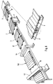
- fig 5A is shown a rather like method and a device respectively, where however three part pallets 3, 3 1 , 3 2 , with goods 41 are brought together for forming a full pallet 203.
- quart pallets which in a first joining and holding station respectively are united into a pair. Two such pairs are brought together and are then fixed in a second joining and fixing station respectively into an intended unit comprising four part pallets.
- a turning station 42 On the way to the second station, there is a turning station 42, which turns each fed pair 90 degrees, after which it is fed forward to the other joining and fixing station respectively.
- the transport means 10 is divided into two parts, one before and one after the turning station 42.
- fig 5C is first of all shown return part pallets 3 and so on e.g. of plastic, which are fed onto the transport means and handled further on in accordance with fig 5, 5A or 5B.
- Fig 6 is first of all illustrated the production of wood pallets 3. Nailing together work pieces and blocks 2, 2 1 , to a completed full pallet 103 takes place in a fully automatic pallet nailing machine 43. Flexible formats may occur in length, width and height.
- the assembled full pallet 103 is automatically forwarded via transports 10 into a saw cutting machine 44 which automatically saws and divides the full pallet 103 into two or more smaller part units 3, 3 1 .
- the part pallets 3 3 1 After sawing through and dividing via the transporter 10, the part pallets 3 3 1 , move into a joining machine 7 where joining takes place to a ready assembled 1 divisible full pallet 103.
Landscapes
- Engineering & Computer Science (AREA)
- Mechanical Engineering (AREA)
- Basic Packing Technique (AREA)
- Coupling Device And Connection With Printed Circuit (AREA)
- Automatic Assembly (AREA)
- Processing Of Terminals (AREA)
- Pallets (AREA)
- Cable Accessories (AREA)
- Nitrogen Condensed Heterocyclic Rings (AREA)
Claims (10)
- Verfahren, um durch Tragblöcke für Paletten (3, 31) oder Tragwände in Paletten gebildete Abstandshalter (2, 21) mittels flexibler Streifen (1) abnehmbar paarweise zu verbinden, dadurch gekennzeichnet, dass eine Förderbahn (10) Abstandshalter (2, 21), die paarweise zusammengepresst werden, zu einer Station (5) zum Verbinden befördert, dass die Abstandshalterpaare (2, 21) mittels einer ringförmigen Bandführung (11) umfasst werden, die vorzugsweise geöffnet werden kann und entlang der ein Band (4) umlaufend angeordnet wird, bis es eine Schlaufe um den Abstandshalter (2, 21) herum bildet, wobei sie eng miteinander verbunden und zusammengeklemmt werden, und dass zugelassen wird, dass das Band (4) die beiden Abstandshalter (2, 21) nach Art einer Schlinge in einer neben einem Förderband (9) für zumindest Abstandshalter (2, 21, .... 2n) angeordneten Umreifungsmaschine (7) umfasst und um diese herumläuft, bevor anschließend die Bandenden (4A, 4B) miteinander verbunden werden, um eine trennbare Verbindungsschlinge (1) zu bilden, die die Abstandshalter (2, 21) paarweise umgibt.
- Verfahren nach Anspruch 1, dadurch gekennzeichnet, dass die Abstandshalter (2, 21) zu einer betreffenden Umreifungsstation (5) lose oder mit ihrer jeweiligen Palette (3, 31) transportiert werden, um sie seitlich gegeneinander zu pressen.
- Verfahren nach Anspruch 1, dadurch gekennzeichnet, dass Kunststoffstreifen (1) mittels Plomben, oder alternativ durch Verschweißen mittels Stahlstreifen mit Plomben, durch Schweißen oder durch Nieten verbunden werden.
- Verfahren nach einem der Ansprüche 1 - 3, dadurch gekennzeichnet, dass die Plomben (13) zugeführt werden, um auf das Band (4), das kontinuierlich von einem Bandmagazin (14) zugeführt wird, aufgefädelt zu werden.
- Verfahren nach einem der Ansprüche 1 - 4, dadurch gekennzeichnet, dass die Umreifungsstation (5) vertikal (16) in Bezug auf die Abstandshalter (2, 21) bewegt wird, um Abstandshalterpaare auf konjugierten unterschiedlichen Niveaus (15, 151) zusammenzupressen.
- Verfahren nach Anspruch 5, dadurch gekennzeichnet, dass die Umreifungsstation (5), die einen Tisch (18) umfasst, der vertikal (16) angehoben werden kann und seitlich (17) verschiebbar ist, wobei der Tisch eine vorstehend erwähnte Bandführungsvorrichtung (11) trägt, derart angeordnet ist, dass sie zwischen einer zurückgezogenen Passierstellung (I) für den Abstandshalter (2, 21) und einer nach vorne bewegten Umreifungsstellung (II) verschoben werden kann, und dass sie jeweils zwischen mindestens zwei Niveaus angehoben werden kann.
- Maschine (20) zum Durchführen eines Verfahrens, um durch Tragblöcke für Paletten (3, 31) oder Tragwände in Paletten gebildete Abstandshalter (2, 21) mittels flexibler Streifen (1) abnehmbar paarweise zu verbinden, nach einem der Ansprüche 1 - 6, dadurch gekennzeichnet, dass sie eine Förderbahn (10) zum Befördern von Abstandshaltern (2, 21) zu einer Verbindungsstation (23) entlang der Förderbahn (10) für die Abstandshalter (2, 21) sowie eine ringförmige Bandführung (11) umfasst, die vorzugsweise geöffnet werden kann und entlang der ein Band (4) umlaufend angeordnet wird, bis es eine Schlinge um den Abstandshalter (2, 21) herum bildet, und dass die Maschine (20) derart eingerichtet ist, dass sie als eine automatische Maschine zum Zuführen von Abstandshaltern (2, 21) nach vorne bis zu einer Stoppstellung (SL) und zum anschließenden Umreifen mittels des Bandes funktioniert, das derart angeordnet ist, dass es kontinuierlich einer Umreifungsmaschine (7) zugeführt wird, die seitlich von der Förderbahn (10) versetzt angeordnet ist.
- Maschine nach Anspruch 7, dadurch gekennzeichnet, dass die ringförmig konstruierte Bandführungs- und Umreifungseinheit (11) aufgrund eines Öffnungsabschnittes (25) geöffnet werden kann, der angelenkt mit einem Rahmenelement (27) verbunden ist (26) und jeweils zwischen einer geschlossenen Umreifungsstellung bzw. einer offenen Stellung verschwenkbar ist.
- Maschine nach Anspruch 8, dadurch gekennzeichnet, dass die Umreifungseinheit (11) auf einem Maschinentisch (18) getragen ist, der seitlich verschiebbar gelagert ist (17), von einem Zylinder (32) beeinflusst ist und vertikal mittels eines Hubzylinders (33), der einen Tischrahmen (34) trägt, anhebbar ist (16).
- Maschine nach einem der Ansprüche 7 - 9, dadurch gekennzeichnet, dass die Förderbahn durch ein Transportband (10) gebildet ist, das zwischen einer Beladestation für Abstandshalter (2, 21, ..., 2n) oder Paletten (3, 31) oder einem Ausgabeteil für umreifte Abstandshalter läuft.
Applications Claiming Priority (3)
| Application Number | Priority Date | Filing Date | Title |
|---|---|---|---|
| SE9604417 | 1996-12-02 | ||
| SE9604417A SE508457C2 (sv) | 1996-12-02 | 1996-12-02 | Sammanfogningsförfarande samt maskin för sammanfogning utav distansorgan |
| PCT/SE1997/002014 WO1998024700A1 (en) | 1996-12-02 | 1997-12-02 | Method and means for interconnecting spacers |
Publications (2)
| Publication Number | Publication Date |
|---|---|
| EP0942872A1 EP0942872A1 (de) | 1999-09-22 |
| EP0942872B1 true EP0942872B1 (de) | 2002-11-13 |
Family
ID=20404818
Family Applications (1)
| Application Number | Title | Priority Date | Filing Date |
|---|---|---|---|
| EP97947245A Expired - Lifetime EP0942872B1 (de) | 1996-12-02 | 1997-12-02 | Verahren und einrichtung zum verbinden von abstandhaltern |
Country Status (11)
| Country | Link |
|---|---|
| US (1) | US6230383B1 (de) |
| EP (1) | EP0942872B1 (de) |
| AT (1) | ATE227673T1 (de) |
| AU (1) | AU5236998A (de) |
| DE (1) | DE69717136T2 (de) |
| DK (1) | DK0942872T3 (de) |
| ES (1) | ES2187831T3 (de) |
| NO (1) | NO324657B1 (de) |
| PT (1) | PT942872E (de) |
| SE (1) | SE508457C2 (de) |
| WO (1) | WO1998024700A1 (de) |
Families Citing this family (7)
| Publication number | Priority date | Publication date | Assignee | Title |
|---|---|---|---|---|
| ITMO20060416A1 (it) * | 2006-12-21 | 2008-06-22 | Bema Srl | Procedimento per la fasciatura di carichi pallettizzati |
| US8733707B2 (en) | 2008-04-17 | 2014-05-27 | The Boeing Company | Line transfer system for airplane |
| US8326587B2 (en) * | 2007-12-13 | 2012-12-04 | The Boeing Company | System, method, and computer program product for predicting cruise orientation of an as-built airplane |
| US9415952B2 (en) * | 2013-03-07 | 2016-08-16 | Daniel Paul Shatley | Sectional palletizer with conveyer system |
| US9327868B1 (en) * | 2014-03-20 | 2016-05-03 | Michael Marquis | Pallet system for cable-enabled loading |
| CN108657652B (zh) * | 2018-07-06 | 2023-09-19 | 安徽马钢物流集装箱联运有限公司 | 一种钢卷集装箱托架及钢卷的装箱方法 |
| US11829936B2 (en) * | 2020-02-18 | 2023-11-28 | Dematic Corp. | Method, container, and transport vehicle for preparation and transportation of shipments of goods |
Family Cites Families (3)
| Publication number | Priority date | Publication date | Assignee | Title |
|---|---|---|---|---|
| US4225259A (en) * | 1979-02-15 | 1980-09-30 | Mcdonnell Douglas Corporation | Pallet coupler |
| US4545482A (en) * | 1984-04-10 | 1985-10-08 | Boise Cascade Corporation | U-Shaped support pad for appliances and the like |
| DE8707837U1 (de) * | 1986-12-03 | 1987-11-12 | Krieger, geb. Erfurt, Hildegard, 33602 Bielefeld | Lastentragelement, insbesondere für eine bzw. an einer Stapelpalette |
-
1996
- 1996-12-02 SE SE9604417A patent/SE508457C2/sv not_active IP Right Cessation
-
1997
- 1997-12-02 WO PCT/SE1997/002014 patent/WO1998024700A1/en not_active Ceased
- 1997-12-02 US US09/308,845 patent/US6230383B1/en not_active Expired - Fee Related
- 1997-12-02 DK DK97947245T patent/DK0942872T3/da active
- 1997-12-02 EP EP97947245A patent/EP0942872B1/de not_active Expired - Lifetime
- 1997-12-02 ES ES97947245T patent/ES2187831T3/es not_active Expired - Lifetime
- 1997-12-02 PT PT97947245T patent/PT942872E/pt unknown
- 1997-12-02 AU AU52369/98A patent/AU5236998A/en not_active Abandoned
- 1997-12-02 AT AT97947245T patent/ATE227673T1/de not_active IP Right Cessation
- 1997-12-02 DE DE69717136T patent/DE69717136T2/de not_active Expired - Lifetime
-
1999
- 1999-05-21 NO NO19992447A patent/NO324657B1/no not_active IP Right Cessation
Also Published As
| Publication number | Publication date |
|---|---|
| SE9604417L (sv) | 1998-06-03 |
| DE69717136T2 (de) | 2003-07-17 |
| AU5236998A (en) | 1998-06-29 |
| DK0942872T3 (da) | 2003-02-24 |
| SE9604417D0 (sv) | 1996-12-02 |
| ATE227673T1 (de) | 2002-11-15 |
| NO324657B1 (no) | 2007-11-26 |
| ES2187831T3 (es) | 2003-06-16 |
| SE508457C2 (sv) | 1998-10-05 |
| EP0942872A1 (de) | 1999-09-22 |
| PT942872E (pt) | 2003-03-31 |
| NO992447L (no) | 1999-05-21 |
| DE69717136D1 (de) | 2002-12-19 |
| NO992447D0 (no) | 1999-05-21 |
| WO1998024700A1 (en) | 1998-06-11 |
| US6230383B1 (en) | 2001-05-15 |
Similar Documents
| Publication | Publication Date | Title |
|---|---|---|
| AU778974B2 (en) | A wrapping method and apparatus | |
| JP2982643B2 (ja) | 袋自動解荷供給方法並びにその装置、及び該装置で使用される袋輸送コンテナ、解束装置、トレー | |
| EP0942872B1 (de) | Verahren und einrichtung zum verbinden von abstandhaltern | |
| US20050223683A1 (en) | Apparatus for banding groups of palletised products | |
| JPH0272021A (ja) | 包装容器用ブランクの移送装置 | |
| EP0759395B1 (de) | Durchfahr-Umreifungsmaschine und Verfahren zur Sicherung einer Last | |
| ZA200409536B (en) | A system and method for creation of load units. | |
| US9032869B2 (en) | Method for applying a strap around a load | |
| CN113386994B (zh) | 一种包装盒捆扎机 | |
| CN113401396B (zh) | 在线式制托盘打包的方法及打包线 | |
| KR101343848B1 (ko) | 자동식 종이가공물 부착장치 | |
| CN216154097U (zh) | 在线式制托盘打包线 | |
| CN109623955B (zh) | 人造板连续压机在线规格锯切设备及在线规格锯切方法 | |
| CN115072040A (zh) | 一种龙骨成品自动包装的系统及方法 | |
| JPH04182261A (ja) | シート状物の取り扱い装置 | |
| CN222905935U (zh) | 自动包装线 | |
| CN223919674U (zh) | 打包翻转机及自动打包生产线 | |
| CN220430692U (zh) | 拖鞋机的扎带进料装置 | |
| JPH07242237A (ja) | 板材積層物用パレット、板材積層物の収納方法、運送方法、梱包・固定方法、固定構造、収納構造及びパレット兼用運搬具並びにパレット付き運搬具若しくはパレット兼用運搬具の収納方法 | |
| CN220076760U (zh) | 成品砌块无托盘自动包装输送线 | |
| CN107310776A (zh) | 一种卷烟成品垛包装系统的自动加固方法 | |
| CN114643746B (zh) | 集装箱液体包装袋套袋装置 | |
| CN118123958B (zh) | 木箱加工输送线及装箱流水线 | |
| JPH04142217A (ja) | プレス梱包装置 | |
| KR20240029936A (ko) | 파렛트 랩핑장치 |
Legal Events
| Date | Code | Title | Description |
|---|---|---|---|
| PUAI | Public reference made under article 153(3) epc to a published international application that has entered the european phase |
Free format text: ORIGINAL CODE: 0009012 |
|
| 17P | Request for examination filed |
Effective date: 19990512 |
|
| AK | Designated contracting states |
Kind code of ref document: A1 Designated state(s): AT BE CH DE DK ES FI FR GB GR IE IT LI LU MC NL PT SE |
|
| 17Q | First examination report despatched |
Effective date: 19991124 |
|
| GRAG | Despatch of communication of intention to grant |
Free format text: ORIGINAL CODE: EPIDOS AGRA |
|
| GRAG | Despatch of communication of intention to grant |
Free format text: ORIGINAL CODE: EPIDOS AGRA |
|
| GRAH | Despatch of communication of intention to grant a patent |
Free format text: ORIGINAL CODE: EPIDOS IGRA |
|
| GRAH | Despatch of communication of intention to grant a patent |
Free format text: ORIGINAL CODE: EPIDOS IGRA |
|
| GRAA | (expected) grant |
Free format text: ORIGINAL CODE: 0009210 |
|
| AK | Designated contracting states |
Kind code of ref document: B1 Designated state(s): AT BE CH DE DK ES FI FR GB GR IE IT LI LU MC NL PT SE |
|
| PG25 | Lapsed in a contracting state [announced via postgrant information from national office to epo] |
Ref country code: NL Free format text: LAPSE BECAUSE OF FAILURE TO SUBMIT A TRANSLATION OF THE DESCRIPTION OR TO PAY THE FEE WITHIN THE PRESCRIBED TIME-LIMIT Effective date: 20021113 Ref country code: LI Free format text: LAPSE BECAUSE OF FAILURE TO SUBMIT A TRANSLATION OF THE DESCRIPTION OR TO PAY THE FEE WITHIN THE PRESCRIBED TIME-LIMIT Effective date: 20021113 Ref country code: GR Free format text: LAPSE BECAUSE OF FAILURE TO SUBMIT A TRANSLATION OF THE DESCRIPTION OR TO PAY THE FEE WITHIN THE PRESCRIBED TIME-LIMIT Effective date: 20021113 Ref country code: CH Free format text: LAPSE BECAUSE OF FAILURE TO SUBMIT A TRANSLATION OF THE DESCRIPTION OR TO PAY THE FEE WITHIN THE PRESCRIBED TIME-LIMIT Effective date: 20021113 Ref country code: BE Free format text: LAPSE BECAUSE OF FAILURE TO SUBMIT A TRANSLATION OF THE DESCRIPTION OR TO PAY THE FEE WITHIN THE PRESCRIBED TIME-LIMIT Effective date: 20021113 |
|
| REF | Corresponds to: |
Ref document number: 227673 Country of ref document: AT Date of ref document: 20021115 Kind code of ref document: T |
|
| REG | Reference to a national code |
Ref country code: GB Ref legal event code: FG4D |
|
| REG | Reference to a national code |
Ref country code: CH Ref legal event code: EP |
|
| PG25 | Lapsed in a contracting state [announced via postgrant information from national office to epo] |
Ref country code: LU Free format text: LAPSE BECAUSE OF NON-PAYMENT OF DUE FEES Effective date: 20021202 |
|
| REG | Reference to a national code |
Ref country code: IE Ref legal event code: FG4D |
|
| REF | Corresponds to: |
Ref document number: 69717136 Country of ref document: DE Date of ref document: 20021219 |
|
| PGFP | Annual fee paid to national office [announced via postgrant information from national office to epo] |
Ref country code: GR Payment date: 20021227 Year of fee payment: 6 |
|
| PGFP | Annual fee paid to national office [announced via postgrant information from national office to epo] |
Ref country code: CH Payment date: 20021230 Year of fee payment: 6 Ref country code: NL Payment date: 20021230 Year of fee payment: 6 |
|
| PG25 | Lapsed in a contracting state [announced via postgrant information from national office to epo] |
Ref country code: SE Free format text: LAPSE BECAUSE OF FAILURE TO SUBMIT A TRANSLATION OF THE DESCRIPTION OR TO PAY THE FEE WITHIN THE PRESCRIBED TIME-LIMIT Effective date: 20030213 |
|
| REG | Reference to a national code |
Ref country code: DK Ref legal event code: T3 |
|
| REG | Reference to a national code |
Ref country code: PT Ref legal event code: TE4A Free format text: JOHAN WELLEMAN SE Effective date: 20030205 Ref country code: PT Ref legal event code: SC4A Free format text: AVAILABILITY OF NATIONAL TRANSLATION Effective date: 20030205 |
|
| NLV1 | Nl: lapsed or annulled due to failure to fulfill the requirements of art. 29p and 29m of the patents act | ||
| REG | Reference to a national code |
Ref country code: CH Ref legal event code: PL |
|
| REG | Reference to a national code |
Ref country code: ES Ref legal event code: FG2A Ref document number: 2187831 Country of ref document: ES Kind code of ref document: T3 |
|
| PG25 | Lapsed in a contracting state [announced via postgrant information from national office to epo] |
Ref country code: MC Free format text: LAPSE BECAUSE OF NON-PAYMENT OF DUE FEES Effective date: 20030701 |
|
| ET | Fr: translation filed | ||
| PLBE | No opposition filed within time limit |
Free format text: ORIGINAL CODE: 0009261 |
|
| STAA | Information on the status of an ep patent application or granted ep patent |
Free format text: STATUS: NO OPPOSITION FILED WITHIN TIME LIMIT |
|
| REG | Reference to a national code |
Ref country code: FR Ref legal event code: CA |
|
| 26N | No opposition filed |
Effective date: 20030814 |
|
| PG25 | Lapsed in a contracting state [announced via postgrant information from national office to epo] |
Ref country code: IT Free format text: LAPSE BECAUSE OF NON-PAYMENT OF DUE FEES Effective date: 20051202 |
|
| PGFP | Annual fee paid to national office [announced via postgrant information from national office to epo] |
Ref country code: IE Payment date: 20091204 Year of fee payment: 13 Ref country code: AT Payment date: 20091216 Year of fee payment: 13 |
|
| PGFP | Annual fee paid to national office [announced via postgrant information from national office to epo] |
Ref country code: PT Payment date: 20091126 Year of fee payment: 13 |
|
| PGFP | Annual fee paid to national office [announced via postgrant information from national office to epo] |
Ref country code: IT Payment date: 20091217 Year of fee payment: 13 |
|
| PGRI | Patent reinstated in contracting state [announced from national office to epo] |
Ref country code: IT Effective date: 20091201 |
|
| REG | Reference to a national code |
Ref country code: PT Ref legal event code: MM4A Free format text: LAPSE DUE TO NON-PAYMENT OF FEES Effective date: 20110602 |
|
| PG25 | Lapsed in a contracting state [announced via postgrant information from national office to epo] |
Ref country code: PT Free format text: LAPSE BECAUSE OF NON-PAYMENT OF DUE FEES Effective date: 20110602 |
|
| PG25 | Lapsed in a contracting state [announced via postgrant information from national office to epo] |
Ref country code: AT Free format text: LAPSE BECAUSE OF NON-PAYMENT OF DUE FEES Effective date: 20101202 |
|
| REG | Reference to a national code |
Ref country code: IE Ref legal event code: MM4A |
|
| PG25 | Lapsed in a contracting state [announced via postgrant information from national office to epo] |
Ref country code: IE Free format text: LAPSE BECAUSE OF NON-PAYMENT OF DUE FEES Effective date: 20101202 |
|
| PG25 | Lapsed in a contracting state [announced via postgrant information from national office to epo] |
Ref country code: IT Free format text: LAPSE BECAUSE OF NON-PAYMENT OF DUE FEES Effective date: 20101202 |
|
| PGFP | Annual fee paid to national office [announced via postgrant information from national office to epo] |
Ref country code: DK Payment date: 20111213 Year of fee payment: 15 |
|
| PGFP | Annual fee paid to national office [announced via postgrant information from national office to epo] |
Ref country code: GB Payment date: 20121121 Year of fee payment: 16 Ref country code: ES Payment date: 20121130 Year of fee payment: 16 |
|
| PGFP | Annual fee paid to national office [announced via postgrant information from national office to epo] |
Ref country code: FR Payment date: 20130125 Year of fee payment: 16 Ref country code: DE Payment date: 20130227 Year of fee payment: 16 |
|
| REG | Reference to a national code |
Ref country code: DK Ref legal event code: EBP |
|
| PG25 | Lapsed in a contracting state [announced via postgrant information from national office to epo] |
Ref country code: DK Free format text: LAPSE BECAUSE OF NON-PAYMENT OF DUE FEES Effective date: 20130102 |
|
| REG | Reference to a national code |
Ref country code: DE Ref legal event code: R119 Ref document number: 69717136 Country of ref document: DE |
|
| GBPC | Gb: european patent ceased through non-payment of renewal fee |
Effective date: 20131202 |
|
| REG | Reference to a national code |
Ref country code: FR Ref legal event code: ST Effective date: 20140829 |
|
| REG | Reference to a national code |
Ref country code: DE Ref legal event code: R119 Ref document number: 69717136 Country of ref document: DE Effective date: 20140701 |
|
| PG25 | Lapsed in a contracting state [announced via postgrant information from national office to epo] |
Ref country code: DE Free format text: LAPSE BECAUSE OF NON-PAYMENT OF DUE FEES Effective date: 20140701 |
|
| PG25 | Lapsed in a contracting state [announced via postgrant information from national office to epo] |
Ref country code: FR Free format text: LAPSE BECAUSE OF NON-PAYMENT OF DUE FEES Effective date: 20131231 Ref country code: GB Free format text: LAPSE BECAUSE OF NON-PAYMENT OF DUE FEES Effective date: 20131202 |
|
| PGFP | Annual fee paid to national office [announced via postgrant information from national office to epo] |
Ref country code: FI Payment date: 20141229 Year of fee payment: 18 |
|
| REG | Reference to a national code |
Ref country code: ES Ref legal event code: FD2A Effective date: 20150401 |
|
| PG25 | Lapsed in a contracting state [announced via postgrant information from national office to epo] |
Ref country code: ES Free format text: LAPSE BECAUSE OF NON-PAYMENT OF DUE FEES Effective date: 20131203 |
|
| PG25 | Lapsed in a contracting state [announced via postgrant information from national office to epo] |
Ref country code: FI Free format text: LAPSE BECAUSE OF NON-PAYMENT OF DUE FEES Effective date: 20151202 |