EP0942849B1 - Fehlertolerantes kraftfahrzeugsteuerungssystem - Google Patents
Fehlertolerantes kraftfahrzeugsteuerungssystem Download PDFInfo
- Publication number
- EP0942849B1 EP0942849B1 EP97952440A EP97952440A EP0942849B1 EP 0942849 B1 EP0942849 B1 EP 0942849B1 EP 97952440 A EP97952440 A EP 97952440A EP 97952440 A EP97952440 A EP 97952440A EP 0942849 B1 EP0942849 B1 EP 0942849B1
- Authority
- EP
- European Patent Office
- Prior art keywords
- control unit
- automobile
- components
- master control
- electronic
- Prior art date
- Legal status (The legal status is an assumption and is not a legal conclusion. Google has not performed a legal analysis and makes no representation as to the accuracy of the status listed.)
- Expired - Lifetime
Links
Images


Classifications
-
- B—PERFORMING OPERATIONS; TRANSPORTING
- B60—VEHICLES IN GENERAL
- B60R—VEHICLES, VEHICLE FITTINGS, OR VEHICLE PARTS, NOT OTHERWISE PROVIDED FOR
- B60R16/00—Electric or fluid circuits specially adapted for vehicles and not otherwise provided for; Arrangement of elements of electric or fluid circuits specially adapted for vehicles and not otherwise provided for
- B60R16/02—Electric or fluid circuits specially adapted for vehicles and not otherwise provided for; Arrangement of elements of electric or fluid circuits specially adapted for vehicles and not otherwise provided for electric constitutive elements
-
- G—PHYSICS
- G06—COMPUTING OR CALCULATING; COUNTING
- G06F—ELECTRIC DIGITAL DATA PROCESSING
- G06F11/00—Error detection; Error correction; Monitoring
- G06F11/07—Responding to the occurrence of a fault, e.g. fault tolerance
- G06F11/16—Error detection or correction of the data by redundancy in hardware
- G06F11/20—Error detection or correction of the data by redundancy in hardware using active fault-masking, e.g. by switching out faulty elements or by switching in spare elements
- G06F11/202—Error detection or correction of the data by redundancy in hardware using active fault-masking, e.g. by switching out faulty elements or by switching in spare elements where processing functionality is redundant
- G06F11/2035—Error detection or correction of the data by redundancy in hardware using active fault-masking, e.g. by switching out faulty elements or by switching in spare elements where processing functionality is redundant without idle spare hardware
-
- G—PHYSICS
- G06—COMPUTING OR CALCULATING; COUNTING
- G06F—ELECTRIC DIGITAL DATA PROCESSING
- G06F11/00—Error detection; Error correction; Monitoring
- G06F11/07—Responding to the occurrence of a fault, e.g. fault tolerance
- G06F11/16—Error detection or correction of the data by redundancy in hardware
- G06F11/20—Error detection or correction of the data by redundancy in hardware using active fault-masking, e.g. by switching out faulty elements or by switching in spare elements
- G06F11/202—Error detection or correction of the data by redundancy in hardware using active fault-masking, e.g. by switching out faulty elements or by switching in spare elements where processing functionality is redundant
- G06F11/2023—Failover techniques
- G06F11/2028—Failover techniques eliminating a faulty processor or activating a spare
-
- B—PERFORMING OPERATIONS; TRANSPORTING
- B60—VEHICLES IN GENERAL
- B60R—VEHICLES, VEHICLE FITTINGS, OR VEHICLE PARTS, NOT OTHERWISE PROVIDED FOR
- B60R16/00—Electric or fluid circuits specially adapted for vehicles and not otherwise provided for; Arrangement of elements of electric or fluid circuits specially adapted for vehicles and not otherwise provided for
- B60R16/02—Electric or fluid circuits specially adapted for vehicles and not otherwise provided for; Arrangement of elements of electric or fluid circuits specially adapted for vehicles and not otherwise provided for electric constitutive elements
- B60R16/03—Electric or fluid circuits specially adapted for vehicles and not otherwise provided for; Arrangement of elements of electric or fluid circuits specially adapted for vehicles and not otherwise provided for electric constitutive elements for supply of electrical power to vehicle subsystems or for
- B60R16/0315—Electric or fluid circuits specially adapted for vehicles and not otherwise provided for; Arrangement of elements of electric or fluid circuits specially adapted for vehicles and not otherwise provided for electric constitutive elements for supply of electrical power to vehicle subsystems or for using multiplexing techniques
-
- B—PERFORMING OPERATIONS; TRANSPORTING
- B60—VEHICLES IN GENERAL
- B60W—CONJOINT CONTROL OF VEHICLE SUB-UNITS OF DIFFERENT TYPE OR DIFFERENT FUNCTION; CONTROL SYSTEMS SPECIALLY ADAPTED FOR HYBRID VEHICLES; ROAD VEHICLE DRIVE CONTROL SYSTEMS FOR PURPOSES NOT RELATED TO THE CONTROL OF A PARTICULAR SUB-UNIT
- B60W50/00—Details of control systems for road vehicle drive control not related to the control of a particular sub-unit, e.g. process diagnostic or vehicle driver interfaces
- B60W2050/0001—Details of the control system
- B60W2050/0002—Automatic control, details of type of controller or control system architecture
- B60W2050/0004—In digital systems, e.g. discrete-time systems involving sampling
- B60W2050/0006—Digital architecture hierarchy
-
- B—PERFORMING OPERATIONS; TRANSPORTING
- B60—VEHICLES IN GENERAL
- B60W—CONJOINT CONTROL OF VEHICLE SUB-UNITS OF DIFFERENT TYPE OR DIFFERENT FUNCTION; CONTROL SYSTEMS SPECIALLY ADAPTED FOR HYBRID VEHICLES; ROAD VEHICLE DRIVE CONTROL SYSTEMS FOR PURPOSES NOT RELATED TO THE CONTROL OF A PARTICULAR SUB-UNIT
- B60W50/00—Details of control systems for road vehicle drive control not related to the control of a particular sub-unit, e.g. process diagnostic or vehicle driver interfaces
- B60W50/02—Ensuring safety in case of control system failures, e.g. by diagnosing, circumventing or fixing failures
- B60W50/029—Adapting to failures or work around with other constraints, e.g. circumvention by avoiding use of failed parts
- B60W2050/0292—Fail-safe or redundant systems, e.g. limp-home or backup systems
-
- B—PERFORMING OPERATIONS; TRANSPORTING
- B60—VEHICLES IN GENERAL
- B60W—CONJOINT CONTROL OF VEHICLE SUB-UNITS OF DIFFERENT TYPE OR DIFFERENT FUNCTION; CONTROL SYSTEMS SPECIALLY ADAPTED FOR HYBRID VEHICLES; ROAD VEHICLE DRIVE CONTROL SYSTEMS FOR PURPOSES NOT RELATED TO THE CONTROL OF A PARTICULAR SUB-UNIT
- B60W50/00—Details of control systems for road vehicle drive control not related to the control of a particular sub-unit, e.g. process diagnostic or vehicle driver interfaces
- B60W50/02—Ensuring safety in case of control system failures, e.g. by diagnosing, circumventing or fixing failures
- B60W50/029—Adapting to failures or work around with other constraints, e.g. circumvention by avoiding use of failed parts
- B60W2050/0297—Control Giving priority to different actuators or systems
Definitions
- This invention relates to a fault resilient automobile control system, an automobile comprising such a system, a method of operating an automobile control system and a computer programmed to perform the steps of the method.
- Modem automobiles are typically equipped with multiple independent electronic components. For instance, most modem automobiles have an electronic engine control system, a computerized antilock braking system (ABS), a vehicle safety system, a lighting control system, a climate control subsystem, and a sound system.
- the engine control system usually employs an electronic controller to maximize fuel economy and minimize harmful emissions.
- the antilock braking system uses electronic sensors and microprocessors to slow an automobile at an optimal rate while preventing skidding.
- the vehicle safety system has a crash response controller that is triggered during a crash to deploy one or more airbags.
- Some recent automobile models are equipped with a navigation system that employs a global positioning system (GPS) receiver to receive positioning signals from a satellite network.
- GPS global positioning system
- the navigation system computes coordinates that locate the vehicle over the surface of the earth with regard to longitude, latitude, and altitude.
- Cellular communication systems have also been introduced into automobiles to enable the driver or occupant to transact telephone calls from their vehicle.
- Most late model automobiles are also constructed with a diagnostic system that analyzes the performance of the automobile engine, air and heating system, and other components (1996 or later for OBD II, 1993 or later for OBD I).
- the inventors have developed a fault-resilient system which solves these problems.
- This invention concerns a fault-resistent automobile control system that integrates diverse and separate automobile components and tolerates component failure.
- a fault-resilient automobile control system for an automobile having multiple electronic automobile components, each electronic automobile component having a local controller for controlling operation of the electronic automobile component, each local controller storing driver software, the controller being arranged so that, when executing the software, the local controller controls the electronic automobile component
- the automobile control system comprising: a master control unit electrically coupled to the electronic automobile components, the master control unit having a computer processor, the electronic components each being arranged to register with the master control unit and to programme the master control unit during initialisation or upon addition to the system, by downloading the driver software for the local controllers and by storing the driver software in the master control unit, the computer processor thereby being programmed to perform control tasks of the local controllers so that in an event that one of the local controllers fails, the computer processor executes the driver software of the failed local controller so that the master control unit controls the electronic automobile component in place of the failed local controller, the master control unit being arranged during operation of the control system to monitor continuously for failure of a local controller, wherein each electronic automobile component
- an automobile comprises a fault-resilient automobile control system according to the first aspect of the invention.
- a method of operating an automobile control system for an automobile having multiple electronic automobile components each electronic automobile component having a local controller for controlling operation of the associated electronic automobile components and switching logic for selectively routing data to the local controller or to the master control unit if the local controller fails, each local controller storing driver software, the driver software arranged so that when executed by the local controller the local controller controls the electronic automobile component, the automobile control system comprising a master control unit coupled to the electronic automobile components, the master control unit having a computer processor, the method comprising the following steps: (1) during initialisation or as the electronic automobile components are added to the system, registering the electronic components with the master control unit and downloading to the master control unit the driver software of the local controllers; (2) storing the driver software of the local controllers on the master control unit (3) continuously monitoring the local electronic controller for their failure; and (4) in an event that one of the electronic controllers fails, executing the driver software of the failed local controller and thereby remotely controlling the associated component from the computer processor.
- the fault-resilient automobile control system includes a master control unit (MCU) electrically coupled via a data communications bus to the electronic automobile components.
- the master control unit has a computer processor programmed to manage data flow over the data communications bus among the electronic automobile components.
- the MCU defines and synchronizes initialization of the bus communications.
- the MCU maintains a routing table to facilitate resource and information sharing among the components.
- the routing table is constructed during initialization to define how data derived at one electronic component is routed to one or more other components.
- the MCU collects data from the source electronic components and routes the data to destination electronic components according to the routing table.
- data collected by an antilock braking system when an automobile is slowing down might be routed to an automatic transmission system for use in determining whether to downshift.
- the MCU's computer processor is programmed to perform the same functions as those performed by local controllers at the electronic components.
- the driver software for all of the local controllers is downloaded and stored at the MCU.
- the master control unit executes the driver software for the failed controller to remotely control the electronic automobile component in place of the failed local controller.
- Switching logic is provided at each of the electronic components.
- the switching logic selectively routes data either to the local controller, assuming the controller is functioning properly, or over the data communications bus to the MCU, circumventing the controller, when the controller is not functioning properly.
- the fault-resilient automobile control system has a secondary control unit (SCU) electrically coupled to the master control unit via the data communications network.
- the secondary control unit has a computer processor that supports many user-based components, such as an entertainment system or a cellular communications system.
- the SCU's computer processor is also programmed with a backup copy of the MCU's data communications code to manage the data flow among the electronic automobile components.
- the SCU is subordinate to and controlled by the MCU on the data communications bus.
- the secondary control unit assumes control of the data communications bus and manages the data flow among the electronic automobile components.
- the fault-resilient automobile control system affords fault tolerance for all of the components as well as for the MCU itself.
- the master control unit and the secondary control unit are general purpose computers which run an open platform multitasking operating system.
- the open architecture affords tremendous flexibility and adaptability to the addition of new automobile components or the reconfiguration of old components.
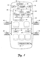
- Fig. 1 shows an automobile control system 20 constructed in an automobile 22 according to one exemplary implementation of this invention.
- the automobile control system 20 has a master control unit (MCU) 24 and a secondary control unit (SCU) 26.
- a dual bus structure consisting of a primary data communications bus 28 and a secondary support bus 30 provide an infrastructure for data communications in the control system 20.
- the primary bus 28 may be implemented using any vehicle bus design currently employed or contemplated by automobile manufactures, such as CAN, ABUS, VAN, J1850, K-BUS, P-BUS, I-BUS, USB, P1394, and so forth.
- the support bus 30 may be implemented as any standard computer data bus, such as PCI, USB, P1394, and the like.
- the master control unit 24 and the secondary control unit 26 are interconnected through the primary vehicle bus 28.
- various electronic automobile components are connected to the master control unit 24 via the primary bus 28.
- the electronic components include an antilock braking system (ABS) 32, an electronic steering system 34, and an engine control system 36.
- ABS antilock braking system
- other components may likewise be connected to the primary vehicle bus 28, such as a security/alarm system, a diagnostic system, a lighting control system, a fuel injection system, an automatic transmission system, and so forth.
- the electronic components shown in Fig. 1 are intelligent components in that they each have their own local controller, typically embodied as a microprocessor.
- the automobile might further include non-intelligent electronic components which do not have local processing capabilities, as is explained below with reference to Figs. 6-8.
- Fig. 1 shows a number of devices connected to the support bus 30. These devices include a climate control system 38, an audio system 40, a navigation system 42 with global positioning system (GPS) antenna 44, and a cellular communications system 46. Door locks and window controls 48 are also connected to the support bus 30.
- the secondary control unit 26 is master of the support bus 30.
- the SCU 26 is also configured as a server to multiple clients 50.
- the clients 50 can be, for example, small hand held or laptop game computers having visual display screens and audio sound cards to provide multimedia entertainment.
- the SCU 26 serves in-car entertainment in the form of movies and games to the clients 50 for the passengers enjoyment.
- the master control unit 24 is the master of the primary vehicle bus 28. All electronic components 32-36, as well as the secondary control unit 26, are slaves to master control unit 24.
- the master control unit 24 manages data flow among the electronic components 32-36 and facilitates resource and information sharing.
- the master control unit 24 provides backup for the intelligent electronic components in the event that any of them fail, and also performs data processing and control functions for non-intelligent electronic components.
- Fig. 2 shows the master control unit 24 in more detail. It has a computer processor 60, volatile memory 62 (e.g., RAM), and non-volatile memory 64 (e.g., ROM, Flash).
- the master control unit 24 also has a bus interface 66 to provide access to the primary bus 28.
- the master control unit 24 runs an open platform operating system 68, which is shown stored in non-volatile memory 64. During runtime, the operating system 68 loads into volatile memory 62 and executes on processor 60.
- the open platform operating system 68 is preferably a real-time, multitasking operating system capable of supporting "plug-and-play" system configuration and providing high stability, security, and efficiency.
- One preferred operating system is a Windows® brand operating system sold by Microsoft Corporation, such as Windows CE® or Windows NT® operating systems.
- the operating system 68 has network management capabilities which enable the master control unit 24 to manage data flow over the primary bus 28 among the electronic components 32-36 and the secondary control unit 26.
- the master control unit 24 initializes the network communication and register subsystem, and handles component configuration.
- the master control unit 24 preferably controls the data flow in a deterministic manner, accepting only predefined data from the electronic components. This is advantageous in that the master control unit provides protection to individual electronic components that are connected on the primary vehicle bus 28 against unexpected or unauthorized commands.
- the networking capabilities enable the master control unit 24 to monitor for deletion or addition of electronic components to the primary bus 28.
- the MCU 24 contains driver software, referenced generally as number 70, for all of the electronic components connected to the primary bus 28.
- the electronic components register with the MCU 24 during initialization, or as they are added to the bus.
- the components' software code 70 may already exist in the MCU memory in dynamic link library (DLL) form which can be linked to the MCU system as components are registered. If the software code of one or more components do not exist in the DLL, a part of this registration involves downloading the software code used to run the components over the primary bus 28 to the master control unit 24.
- Fig. 2 shows driver software 70 for local controllers LC(1), LC(2), ... LC(N) of intelligent electronic components (i.e., components with local controllers) stored in the non-volatile memory 64.
- Fig. 2 also shows executable code for the non-intelligent components NIC(1), NIC(2), ..., NIC(M) (i.e., components without local controllers), referenced general as number 72, stored in non-volatile
- the MCU 24 assumes control of that component and assigns to the failed component a highest execution priority to ensure uninterrupted performance. For instance, if the processor in the ABS fails, the MCU 24 runs the local controller driver, say driver LC(1), to perform the functions of the failed processor for the antilock braking system. Switching logic is provided at the failed component to transfer control to the MCU. Once the MCU 24 assumes control of a component, the MCU 24 performs its data flow management functions on a resource available basis.
- the operating system 68 is a real-time, deterministic operating system that has the processing power capable of concurrently supporting multiple critical components.
- the MCU 24 employs a priority table 74 which specifies an ordered ranking for executing the failed devices.
- the priority table 74 is constructed during initialization as the components register with the MCU 24.
- the MCU 24 assigns a priority rating to each of the electronic automobile components and stores the association in a table in the non-volatile memory 64..
- the priority rating is associated through the table's data structure to identifiers for the driver software 70 and executable code 72.
- the priority is predetermined by the automobile manufacturer based upon which components register with the MCU 24. It is noted that the priority table 74 may alternatively be reconstructed from scratch each start cycle and maintained in volatile memory 62.
- the priority table 74 establishes a priority of operation in the event that more than one component fails.
- the priority table 74 assigns processing resources disproportionately to the highest priority rated component first, followed in order by the lower priority rated components. For instance, the driver software for the antilock braking system might be assigned the highest priority rating to ensure that the MCU 24 has sufficient resources to handle the braking system in the event it fails, even though other components (such as the security system) might also fail during that time.
- the components are assigned a "critical” rating, meaning that they are given the highest priority available, a "normal” rating, meaning that they can be given a lower priority if a critical component concurrently fails, or a "lowest” rating, meaning that they will receive MCU resources only after all components with higher priority have been handled.
- the MCU 24 also maintains a routing table 76 in volatile memory 62.
- the routing table 76 is constructed during initialization to define which data is passed and shared among the active electronic components.
- the table might define a data structure having a source field that contains an identifier of an electronic component from where certain data is generated, and a destination field that contains a list of one or more components to which the certain data is to be routed by the MCU 24.
- data collected by the ABS 32 i.e., a source component
- the fuel injection control system i.e., destination components.
- the source and destination fields are correlated in the table 76.
- the MCU 24 collects data from the electronic components identified in the source fields (such as the ABS), indexes the routing table 76 to corresponding destination fields, and routes the data to the electronic components (such as the automatic transmission control system or fuel injection system) listed in the corresponding destination fields.
- the routing table enables the MCU 24 to facilitate data sharing among the components.
- Fig. 3 shows an exemplary construction of an intelligent electronic automobile component, referenced generally as number 80.
- the automobile component 80 generally comprises a mechanical device 82 (such as brakes, engine, transmission, etc.) which is controlled through an electronically-controlled actuator 84.
- a local controller 86 is coupled through a driver 88 to send electronic command signals that control the actuator and hence, the mechanical apparatus 82.
- the local controller 86 can be implemented as a microprocessor, digital signal processor, dedicated ASIC (application specific integrated circuit), or the like.
- a sensor 90 monitors the mechanical apparatus 82 and generates data indicative of operation to provide feedback information to the local controller 86.
- the local controller 86 also has an interface to the primary vehicle bus 28. This construction of the electronic automobile component is customary and known in the art.
- An aspect of this invention is to modify the existing electronic automobile component 80 to include switching logic 92.
- the switching logic 92 is interfaced between the local controller 86 and the driver 88 and sensor 90.
- the switching logic 92 also has its own connection to the primary bus 28 which bypasses the local controller 86.
- the switching logic 92 selectively routes data received from the sensor 90 to either the local controller 86 or directly to the primary bus 28.
- the switching logic 92 directs the data to the local controller 86 when the controller is functioning properly. In the event that the controller is not functioning properly, however, the switching logic 92 routes data flow to the bus 28, circumventing the failed local controller 86, so that the MCU 24 can control the component over the primary bus 28.
- the secondary control unit 26 is preferably a general purpose computer capable of supporting multiple applications.
- the SCU 26 has a processor 100 (e.g., SH3 from Hitachi, Ltd. or Pentium® microprocessor from Intel Corporation), volatile memory 102 (e.g., RAM), and non-volatile memory 104 (e.g., ROM, Flash, hard disk, etc.).
- the SCU 26 has a primary bus interface 106 to provide access to the primary vehicle bus 28 and a support bus interface 108 to provide access to the support bus 30.
- the SCU 26 runs an open platform operating system 110 which supports multiple applications. Using an open platform operating system and an open computer system architecture, various software applications and hardware peripherals can be supported by the SCU 26 on the support bus 30. This is advantageous in that the software applications do not need to be dedicated to specially designed embedded systems.
- the open hardware architecture is preferably running a multitasking operating system that employs a graphical user interface.
- One preferred operating system is a Windows® brand operating system sold by Microsoft Corporation, such as Windows 95® or Windows NT® or other derivative versions of Windows®.
- a multitasking operating system allows simultaneous execution of multiple applications.
- the SCU 26 might also include at least one storage drive-such as a CD ROM drive, PC Card drive, or a floppy disk drive-which permits use of portable storage media.
- a CD ROM drive enables application-related CDs, as well as musical, video, game, or other types of entertainment CDs.
- the SCU 26 is constructed and sized to mount in the dashboard of the automobile.
- a detailed explanation of one suitable construction of a secondary control unit 26 is described in U.S. Patent Application Serial Number 08/564,586, entitled "Vehicle Computer System," which was filed November 29, 1995, in the names of Richard D. Beckert, Mark M. Moeller, and William Wong. This application is assigned to Microsoft Corporation and is hereby incorporated by reference.
- the secondary control unit 26 is slave to the master control unit 24 on the vehicle bus 28, but is a master to clients 50 and other electronic components 38-48 connected to the support bus 30. dashboard or other suitable location.
- the SCU 26 can function as a server to the clients 50, such as to serve games, music, movies or other forms of entertainment.
- the SCU 26 maintains an up-to-date copy of executable code 112 run by the MCU 24 to manage data flow among the components.
- the MCU code 112 is downloaded to the SCU 26 during initialization and stored in the non-volatile memory 84.
- the secondary control unit 26 executes the MCU code 112 to assume the master responsibility of data flow management on the primary bus 28.
- Fig. 5 shows a state diagram of the automobile control system.
- the startup is triggered by turning on power to the automobile.
- the master control unit 24 runs an initialization procedure to boot the operating system and loads from non-volatile memory all of the driver software 70 for intelligent components and executable code 72 for non-intelligent components into the volatile memory.
- These software programs correspond to components that are pre-known to the MCU 24 through previous registration.
- the MCU 24 runs a dynamic configuration procedure which checks if any new component has been added to or old components removed from the primary vehicle bus. The MCU 24 polls the existing components and sends out requests for new components. Components which are still attached and functioning respond to the MCU 24. New components also respond and subsequently register with the MCU 24. Components that have been removed, of course, do not respond to the polling signals.
- the MCU 24 constructs the priority table 74 and stores it in non-volatile memory 104.
- the MCU 24 also constructs the routing table 76 based upon the existing active components.
- the MCU 24 downloads a copy of its code to the SCU 26 over the primary bus 28. Following this initialization sequence, the MCU enters its normal operating state 126. If the MCU fails, control is shifted back to the SCU 26 (as indicated by the MCU FAIL arrow). If the MCU is subsequently restored, control is returned to the MCU 24 (as indicated by the READY arrow).
- the MCU 24 continuously monitors for failure of any electronic components. If the MCU 24 detects a component failure, the MCU 24 reconfigures the routing and priority tables dynamically and assumes control of the failed component (as indicated by the COMPONENT FAIL arrow back to state 122).
- Figs. 6-8 show the fault tolerant control strategies implemented by the automobile control system.
- Fig. 6 shows the automobile control system 20 as having the MCU 24 and two intelligent electronic components 80(1), 80(2) and two non-intelligent components 130(1), 130(2) connected to the primary bus 28.
- the system further includes the SCU 26 connected to both the primary bus 28 and the support bus 30, and two clients 50 and the audio system 40 coupled to the support bus 30.
- the master control unit 24 is master to the primary bus 28 and to the secondary control unit 26.
- the master control unit 24 manages the data flow over the primary bus 28 and performs the data processing and control functions for the non-intelligent components 130(1), 130(2).
- the MCU 24 continuously monitors the intelligent components 80(1), 80(2) to detect whether the local controllers 86(1), 86(2) are functioning properly.
- the MCU 24 and SCU 26 operate cooperatively, or independently, of one another in normal circumstances, except that the SCU 26 checks with the MCU 24 at regular intervals for signs of failure.
- the MCU 24 controls all data communications on the primary bus 28, it also maintains the security and integrity of the primary bus 28 through continuous monitoring of messages sent by the electronic components, and particularly the SCU 26 since it is an open system. Should the SCU 26 become corrupted and attempt to gain unauthorized control of any electronic component on the primary bus 28, the MCU 24 will disable communication from the SCU 26 by altering its status in the configuration and routing tables. This action relegates the SCU 26 to a passive device which only receives messages and cannot transmit them over the primary bus 28. The MCU 24 will then attempt to select another candidate to designate as a surrogate secondary control unit, going through the process states 122 and 124 as described in Fig. 5.
- Fig. 7 shows a case in which a local controller 86(1) fails.
- the switching logic 92(1) diverts data flow from the local controller 86(1) directly to the primary bus 28.
- the master control unit 24 assumes control of the component 80(1) using the component driver 86(1)' stored at the MCU 24.
- the MCU 24 assigns the highest execution priority to ensure uninterrupted performance of the failed component. For instance, if the microprocessor in the ABS fails, the MCU 24 assumes the functions of the ABS microprocessor and provides uninterrupted service to the ABS component.
- the MCU 24 continues to manage data flow between components on a resource available basis.
- Fig. 8 shows a case in which the MCU 24 fails.
- the SCU 26 detects when the MCU 24 fails through continuous monitoring or alternatively through a non-maskable interrupt generated by the MCU 24 immediately prior to failure.
- the SCU 26 assumes the basic data flow management and control functions of the MCU 24, as well as the processing functions for non-intelligent components 130(1) and 130(2).
- the SCU 26 runs the local copy of the MCU code 26' to become the surrogate master of the primary bus 28 and the components 80(1), 80(2), 130(1), 130(2) connected thereto. In this implementation, however, the SCU 26 does not assume the functions of any failed local controller of a component on the vehicle bus.
- the SCU 26 assigns the highest priority to performance of the basic data flow management and control function of the failed MCU 24, and performs all other functions on a resource available basis.
- the fault-resilient automobile control system offers many advantages. It integrates the electronic components and facilitates data sharing and communication among them. The system also provides single point fault-tolerance in that every component and the master control unit can fail one time without loss of services. The system affords tremendous flexibility when installing system components in a vehicle. Each component or bus can be installed as an upgrade feature to provide full system functionality. When a new component is installed, a driver for that component is merely loaded at the MCU to enable backup in the event of failure.
Landscapes
- Engineering & Computer Science (AREA)
- Theoretical Computer Science (AREA)
- Quality & Reliability (AREA)
- Physics & Mathematics (AREA)
- General Engineering & Computer Science (AREA)
- General Physics & Mathematics (AREA)
- Mechanical Engineering (AREA)
- Hardware Redundancy (AREA)
- Small-Scale Networks (AREA)
Claims (18)
- Fehlertolerantes Kraftfahrzeugsteuerungssystem (20) für ein Kraftfahrzeug mit einer Vielzahl von elektronischen Kraftfahrzeugkomponenten (32, 34, 36),
wobei jede elektronische Kraftfahrzeugkomponente (32, 34, 36) einen lokalen Controller (86) zum Steuern des Betriebs der elektronischen Kraftfahrzeugkomponente aufweist, wobei jeder lokaler Controller (86) Treibersoftware speichert und der Controller (86) derart ausgestaltet ist, dass er bei Ausführung der Software die elektronische Kraftfahrzeugskomponente (32, 34, 36) steuert,
wobei das Kraftfahrzeugsteuerungssystem (20) umfasst: eine elektrisch mit den elektronischen Kraftfahrzeugkomponenten verbundene Master-Steuereinheit (24), die einen Computerprozessor (60) aufweist, wobei jede der elektronischen Komponenten (32, 34, 26) zum Registrieren bei der Master-Steuereinheit (24) und zum Programmieren der Master-Steuereinheit (24) während der Initialisierung und beim Hinzufügen zu dem System durch Herunterladen der Treibersoftware für die lokalen Controller und durch Speichern der Treibersoftware in der Master-Steuereinheit (24) ausgestaltet ist, wobei der Computerprozessor dabei zum Durchführen der Steueraufgaben des lokalen Controllers (86) programmiert ist, so dass in einem Falle eines Ausfalls einer der lokalen Controller (86) der Computerprozessor (60) die Treibersoftware des ausgefallenen lokalen Controllers ausführt, so dass die Master-Steuereinheit (24) die elektronische Kraftfahrzeugkomponente (32, 34, 36) statt des ausgefallenen lokalen Controllers steuert, wobei die Master-Steuereinheit (24) während des Betriebs des Steuerungssystems zum kontinuierlichen Überwachen des Ausfalls eines lokalen Controllers (86) ausgestaltet ist,
worin jede elektronische Kraftfahrzeugkomponente (32, 34, 36) eine Schaltlogik umfasst, die zum selektiven Weiterleiten von Daten zu dem lokalen Controller (86) oder zu der Master-Steuereinheit (24) bei Ausfall des lokalen Controllers (86) ausgestaltet ist. - Fehlertolerantes Kraftfahrzeugsteuerungssystem nach Anspruch 1, worin die Master-Steuereinheit (24) ein Betriebssystem für offene Plattformen aufweist, das auf dem Computerprozessor (60) ausgeführt wird.
- Fehlertolerantes Kraftfahrzeugsteuerungssystem nach Anspruch 1 oder 2, worin die Master-Steuereinheit (24) ein Multitasking-Betriebssystem aufweist, das auf dem Computerprozessor (60) ausgeführt wird.
- Fehlertolerantes Kraftfahrzeugsteuerungssystem nach einem der vorangegangenen Ansprüche, worin die Master-Steuereinheit (24) Datenkommunikation zwischen den elektronischen Kraftfahrzeugkomponenten (32, 34, 36) ermöglicht.
- Fehlertolerantes Kraftfahrzeugsteuerungssystem nach einem der vorangegangenen Ansprüche, worin die Master-Steuereinheit (24) eine Routing-Tabelle (76) führt, die die Master-Steuereinheit (24) zum Routen von durch eine elektronische Kraftfahrzeugkomponente (32, 34, 36) detektierten Daten zu einer oder mehreren anderen elektronischen Kraftfahrzeugkomponenten (32, 34, 36) verwendet.
- Fehlertolerantes Kraftfahrzeugsteuerungssystem nach einem der vorangegangenen Ansprüche, worin die Master-Steuereinheit (24) einen Speicher (64) aufweist und eine Prioritätstabelle (74) in dem Speicher (64) führt, wobei über die Prioritätstabelle (74) elektronischen Kraftfahrzeugkomponenten (32, 34, 36) eine entsprechende Prioritätsbewertung zugeordnet ist, wobei die Master-Steuereinheit (24) die Aufgaben eines oder mehrerer ausgefallener lokaler Controller (86) in einer Reihenfolge gemäß der Prioritätsbewertung der elektronischen Kraftfahrzeugkomponenten (32, 34, 36) in der Prioritätstabelle (74) handhabt.
- Fehlertolerantes Kraftfahrzeugsteuerungssystem nach einem der vorangegangenen Ansprüche, in dem die elektronischen Kraftfahrzeugkomponenten (32, 34, 36) ferner nicht-intelligente Komponenten (130) umfassen, die ohne lokale Controller ausgebildet sind, und worin die Master-Steuereinheit (24) die Datenverarbeitung und Steuerungsfunktionen für die nicht-intelligenten Komponenten (130) durchführt.
- Fehlertolerantes Kraftfahrzeugsteuerungssystem nach einem der vorangegangenen Ansprüche, das zusätzlich ein Datenkommunikationsnetzwerk aufweist, das die elektronischen Kraftfahrzeugkomponenten (32, 34, 36) und die Master-Steuereinheit (24) untereinander verbindet.
- Fehlertolerantes Kraftfahrzeugsteuerungssystem nach Anspruch 8, worin die Master-Steuereinheit (24) elektrisch mit den elektronischen Kraftfahrzeugkomponenten über das Datenkommunikationswerk verbunden ist und zum Verwalten des Datenflusses über das Datenkommunikationsnetzwerk zwischen den elektronischen Kraftfahrzeugkomponenten (32, 34, 36) programmiert ist.
- Fehlertolerantes Kraftfahrzeugsteuerungssystem nach einem der vorangegangenen Ansprüche, das zusätzlich eine untergeordnete Steuereinheit (26) umfasst, die elektrisch mit der Master-Steuereinheit (24) verbunden ist, wobei die untergeordnete Steuereinheit (26) einen Computerprozessor (100) aufweist, der zum Verwalten des Datenflusses zwischen den elektronischen Kraftfahrzeugkomponenten (32, 34, 36) in dem Falle eines Ausfalls der Master-Steuereinheit (24) programmiert ist.
- Fehlertolerantes Kraftfahrzeugsteuerungssystem nach Anspruch 10, worin die untergeordnete Steuereinheit (26) ein Multitasking-Betriebssystem für offene Plattformen aufweist, das auf einem Computerprozessor (100) der untergeordneten Steuereinheit (26) ausgeführt wird.
- Fehlertolerantes Kraftfahrzeugsteuerungssystem nach Anspruch 10 oder 11, das zusätzlich umfasst:eine doppelte Busdatenstruktur mit einem primären Bus (28) und einem Unterstützungsbus (30),wobei der primäre Bus (29) die elektronischen Kraftfahrzeugkomponenten (32, 34, 36), die Master-Steuereinheit (24) und die untergeordnete Steuereinheit (26) untereinander verbindet und
wobei der Unterstützungsbus (30) mit der untergeordneten Steuereinheit (26) zum Bilden einer Schnittstelle für ein oder mehrere andere Geräte verbunden ist. - Fehlertolerantes Kraftfahrzeugsteuerungssystem nach einem der Ansprüche 10 bis 12, worin die Master-Steuereinheit (24) den Datenfluss zwischen den elektronischen Kraftfahrzeugkomponenten (32, 34, 36) und der untergeordneten Steuereinheit (26) über einen primären Bus verwaltet und in dem Fall, dass die untergeordnete Steuereinheit (26) versucht, unberechtigte Kontrolle über eine der elektronischen Kraftfahrzeugkomponenten (32, 34, 36) auf dem primären Bus (28) zu erlangen, die Master-Steuereinheit (24) zum Abschalten der von der untergeordneten Steuereinheit (26) auf den primären Bus (28) kommenden Kommunikation ausgestaltet ist.
- Fehlertolerantes Kraftfahrzeugsteuerungssystem nach Anspruch 8 oder 9, worin die auf einem der elektronischen Kraftfahrzeugkomponenten (32, 34, 36) angesiedelte Schaltlogik ausgestaltet ist zum Weiterleiten von Daten zu:(i) dem lokalen Controller (86) der elektronischen Kraftfahrzeugkomponente, wenn der lokale Controller korrekt arbeitet oder(ii) dem Datenkommunikationsnetzwerk unter Umgehung des lokalen Controllers (86), wenn der lokale Controller (86) nicht korrekt arbeitet,worin in dem Fall eines Ausfalls eines lokalen Controllers (86) die Schaltlogik die Daten zu der Master-Steuereinheit (24) über das Datenkommunikationsnetzwerk durch Überbrücken des ausgefallenen lokalen Controllers (86) weiterleitet und die Master-Steuereinheit (24) die Aufgaben des ausgefallenen lokalen Controllers (86) durchführt.
- Kraftfahrzeug, das ein fehlertolerantes Kraftfahrzeugsteuerungssystem nach einem der vorangegangenen Ansprüche umfasst.
- Verfahren zum Betrieb eines Kraftfahrzeugsteuerungssystem (20) für ein Kraftfahrzeug mit einer Vielzahl von elektronischen Kraftfahrzeugkomponenten (32, 34, 36), wobei jede elektronische Kraftfahrzeugkomponente einen lokalen Controller (86) zum Steuern des Betriebs der zugehörigen elektronischen Kraftfahrzeugkomponenten und Schaltlogik zum selektiven Weiterleiten von Daten zu dem lokalen Controller (86) oder zu der Master-Steuereinheit (24) bei Ausfall des lokales Controllers (86) aufweist, wobei jeder der lokalen Controller Treibersoftware speichert, die derart ausgestaltet ist, dass, wenn sie durch den lokalen Controller (86) ausgeführt wird, der lokale Controller (86) die elektronische Kraftfahrzeugkomponente (32, 34, 36) steuert, wobei das Kraftfahrzeugsteuerungssystem eine mit den elektronischen Kraftfahrzeugkomponenten verbundene Master-Steuereinheit (24) umfasst, die einen Computerprozessor (60) aufweist, wobei das Verfahren die folgenden Schritte umfasst:(1) während der Initialisierung oder bei Hinzufügen von elektronischen Kraftfahrzeugkomponenten (32, 34, 36) zu dem System, das Registrieren der elektronischen Komponenten (32, 34, 36) bei der Master-Steuereinheit (24) und das Herunterladen der Treibersoftware der lokalen Controller auf die Master-Steuereinheit (24),(2) Speichern der Treibersoftware des lokalen Controllers auf der Master-Steuereinheit,(3) Kontinuierliches Überwachen der lokalen elektronischen Controller (86) hinsichtlich deren Ausfall und(4) in dem Fall, dass einer der elektronischen Controller (86) ausfällt, das Ausführen der Treibersoftware des ausgefallenen lokalen Controllers und dadurch das entfernte Steuern der zugehörigen Komponente von dem Computerprozessor (60) aus.
- Verfahren nach Anspruch 16, wobei das System zusätzlich eine mit der Master-Steuereinheit (24) elektrisch verbundene untergeordnete Steuereinheit (26) umfasst, worin das Verfahren zusätzlich die folgenden Schritte umfasst:(1) Überwachen der Master-Steuereinheit (24) und(2) in dem Fall, dass die Master-Steuereinheit ausfällt, das Verwalten der Datenkommunikation unter den lokalen elektronischen Controllern (86) von der untergeordneten Steuereinheit (26) aus.
- Computer, der zum Durchführen der Schritte des Verfahrens nach Anspruch 16 oder 17 programmiert ist.
Applications Claiming Priority (3)
| Application Number | Priority Date | Filing Date | Title |
|---|---|---|---|
| US08/771,343 US5957985A (en) | 1996-12-16 | 1996-12-16 | Fault-resilient automobile control system |
| US771343 | 1996-12-16 | ||
| PCT/US1997/023030 WO1998026958A1 (en) | 1996-12-16 | 1997-12-10 | Fault-resilient automobile control system |
Publications (2)
| Publication Number | Publication Date |
|---|---|
| EP0942849A1 EP0942849A1 (de) | 1999-09-22 |
| EP0942849B1 true EP0942849B1 (de) | 2007-01-31 |
Family
ID=25091511
Family Applications (1)
| Application Number | Title | Priority Date | Filing Date |
|---|---|---|---|
| EP97952440A Expired - Lifetime EP0942849B1 (de) | 1996-12-16 | 1997-12-10 | Fehlertolerantes kraftfahrzeugsteuerungssystem |
Country Status (7)
| Country | Link |
|---|---|
| US (1) | US5957985A (de) |
| EP (1) | EP0942849B1 (de) |
| JP (1) | JP4091126B2 (de) |
| KR (1) | KR20000057625A (de) |
| CA (1) | CA2275246C (de) |
| DE (1) | DE69737308T2 (de) |
| WO (1) | WO1998026958A1 (de) |
Cited By (2)
| Publication number | Priority date | Publication date | Assignee | Title |
|---|---|---|---|---|
| WO2018177360A1 (zh) * | 2017-03-31 | 2018-10-04 | 比亚迪股份有限公司 | 混合动力汽车的整车控制方法和动力系统 |
| KR20200006091A (ko) * | 2017-06-23 | 2020-01-17 | 닛산 지도우샤 가부시키가이샤 | 주차 제어 방법 및 주차 제어 장치 |
Families Citing this family (169)
| Publication number | Priority date | Publication date | Assignee | Title |
|---|---|---|---|---|
| JP3328296B2 (ja) * | 1997-05-21 | 2002-09-24 | シーメンス アクチエンゲゼルシヤフト | 乗員保護装置用制御システムおよび乗員保護装置用制御システムの制御方法 |
| JP3731980B2 (ja) * | 1997-08-20 | 2006-01-05 | 富士通株式会社 | コンピュータネットワークシステム及び携帯型コンピュータ |
| DE19753907A1 (de) * | 1997-12-05 | 1999-06-10 | Itt Mfg Enterprises Inc | Verbundsystem zur Regelung des Fahrverhaltens eines Kraftfahrzeugs |
| ES2147119B1 (es) * | 1998-03-10 | 2001-03-16 | Mecanismos Aux Es Ind S L | Sistema para transferir informacion binaria. |
| JPH11341020A (ja) * | 1998-05-22 | 1999-12-10 | Yazaki Corp | 多重通信システム |
| US6150925A (en) * | 1998-06-03 | 2000-11-21 | Intel Corporation | Connecting devices to in-car personal computers |
| US6311162B1 (en) * | 1998-07-25 | 2001-10-30 | Ernst F. Reichwein | Interactive symptomatic recording system and methods |
| US7103646B1 (en) * | 1998-08-07 | 2006-09-05 | Hitachi, Ltd. | Distributed control system and information processing system |
| US20030204549A1 (en) * | 1998-10-22 | 2003-10-30 | Wolfgang Eibach | Operating system for handling dynamic and static tasks |
| AU2024200A (en) * | 1998-11-13 | 2000-06-05 | Brook Lang | A motor vehicle entertainment system |
| DE19853665B4 (de) | 1998-11-20 | 2005-06-30 | Siemens Ag | Fahrzeugkommunikationssystem und Verfahren zum Austausch von Daten in einem Kraftfahrzeug |
| CA2280571A1 (en) * | 1998-11-30 | 2000-05-30 | Daimlerchrysler Corporation | J1850 application specific integrated circuit (asic) and messaging technique |
| FR2790857B1 (fr) * | 1999-03-12 | 2001-09-07 | Siemens Automotive Sa | Systeme de securite pour vehicule automobile |
| DE10009366A1 (de) * | 1999-03-22 | 2000-09-28 | Continental Teves Ag & Co Ohg | Schaltungsanordnung und Verfahren zur Konfiguration einer Schnittstelle von einer Steuerungs- oder Regelungseinrichtung |
| JP2000297444A (ja) * | 1999-04-13 | 2000-10-24 | Komatsu Ltd | 建設機械の情報管理装置 |
| DE19918407C2 (de) * | 1999-04-22 | 2003-02-06 | Deutsche Bahn Ag | Bremssystem für einen Zug |
| US7213061B1 (en) | 1999-04-29 | 2007-05-01 | Amx Llc | Internet control system and method |
| US6657646B2 (en) | 1999-06-08 | 2003-12-02 | Amx Corporation | System and method for multimedia display |
| US6865596B1 (en) * | 1999-06-09 | 2005-03-08 | Amx Corporation | Method and system for operating virtual devices by master controllers in a control system |
| DE19931838C1 (de) * | 1999-07-09 | 2001-10-31 | Daimler Chrysler Ag | Verfahren zur Überprüfung einer ringförmigen optischen Netzleitung zur Datenübertragung zwischen mehreren Netzteilnehmern in einem Kraftfahrzeug |
| DE19932405B4 (de) * | 1999-07-14 | 2008-01-31 | Grundig Multimedia B.V. | Verfahren zur Aufnahme einer neuen Komponente in ein Bussystem |
| FR2796735B1 (fr) * | 1999-07-21 | 2002-08-16 | Peugeot Citroen Automobiles Sa | Procede et systeme de configuration de calculateurs |
| US6553290B1 (en) * | 2000-02-09 | 2003-04-22 | Oshkosh Truck Corporation | Equipment service vehicle having on-board diagnostic system |
| US7127331B2 (en) | 1999-07-30 | 2006-10-24 | Oshkosh Truck Corporation | Turret operator interface system and method for a fire fighting vehicle |
| US6909944B2 (en) * | 1999-07-30 | 2005-06-21 | Oshkosh Truck Corporation | Vehicle control system and method |
| US7184866B2 (en) * | 1999-07-30 | 2007-02-27 | Oshkosh Truck Corporation | Equipment service vehicle with remote monitoring |
| US6757597B2 (en) | 2001-01-31 | 2004-06-29 | Oshkosh Truck | A/C bus assembly for electronic traction vehicle |
| US7006902B2 (en) | 1999-07-30 | 2006-02-28 | Oshkosh Truck Corporation | Control system and method for an equipment service vehicle |
| US7729831B2 (en) | 1999-07-30 | 2010-06-01 | Oshkosh Corporation | Concrete placement vehicle control system and method |
| US7184862B2 (en) * | 1999-07-30 | 2007-02-27 | Oshkosh Truck Corporation | Turret targeting system and method for a fire fighting vehicle |
| US7107129B2 (en) | 2002-02-28 | 2006-09-12 | Oshkosh Truck Corporation | Turret positioning system and method for a fire fighting vehicle |
| US7072745B2 (en) | 1999-07-30 | 2006-07-04 | Oshkosh Truck Corporation | Refuse vehicle control system and method |
| US6993421B2 (en) * | 1999-07-30 | 2006-01-31 | Oshkosh Truck Corporation | Equipment service vehicle with network-assisted vehicle service and repair |
| US6882917B2 (en) * | 1999-07-30 | 2005-04-19 | Oshkosh Truck Corporation | Steering control system and method |
| US6421593B1 (en) * | 1999-07-30 | 2002-07-16 | Pierce Manufacturing Inc. | Military vehicle having cooperative control network with distributed I/O interfacing |
| US6922615B2 (en) * | 1999-07-30 | 2005-07-26 | Oshkosh Truck Corporation | Turret envelope control system and method for a fire fighting vehicle |
| US7024296B2 (en) * | 1999-07-30 | 2006-04-04 | Oshkosh Truck Corporation | Control system and method for an equipment service vehicle |
| US6885920B2 (en) | 1999-07-30 | 2005-04-26 | Oshkosh Truck Corporation | Control system and method for electric vehicle |
| US7162332B2 (en) | 1999-07-30 | 2007-01-09 | Oshkosh Truck Corporation | Turret deployment system and method for a fire fighting vehicle |
| US6845398B1 (en) * | 1999-08-02 | 2005-01-18 | Lucent Technologies Inc. | Wireless multimedia player |
| TW420771B (en) * | 1999-08-14 | 2001-02-01 | Ibm | Electronic control system for controlling the function of a processing system and method for managing system fault situations of the electronic control system |
| DE19946022A1 (de) | 1999-09-25 | 2001-04-26 | Bosch Gmbh Robert | Steuerungsvorrichtung und -verfahren zur Festlegung einer Informationsausgabe-Rangfolge mehrerer Informationsquellen, insbesondere Audioquellen |
| JP3900778B2 (ja) * | 2000-02-22 | 2007-04-04 | アイシン・エィ・ダブリュ株式会社 | ナビゲーション装置 |
| FR2808353B1 (fr) * | 2000-04-28 | 2003-12-05 | Airsys Atm S A | Dispositif de gestion d'entrees/sorties redondant, notamment de routage informatique |
| DE10023705A1 (de) * | 2000-05-16 | 2001-11-22 | Bosch Gmbh Robert | Verfahren zur Zugriffssteuerung auf Geräte in einem Fahrzeugkommunikationsnetz |
| DE10026124A1 (de) | 2000-05-26 | 2001-11-29 | Bayerische Motoren Werke Ag | Schaltungsanordnung für ein Kraftfahrzeug |
| DE10030996B4 (de) * | 2000-06-30 | 2010-07-22 | Robert Bosch Gmbh | Vorrichtung und Verfahren zur Steuerung von Betriebsabläufen, insbesondere bei einem Fahrzeug |
| US20020173885A1 (en) * | 2001-03-13 | 2002-11-21 | Lowrey Larkin Hill | Internet-based system for monitoring vehicles |
| TW544559B (en) * | 2000-09-19 | 2003-08-01 | Mitsubishi Motors Corp | Failure diagnosis apparatus and failure diagnosis method of vehicular electronic control system |
| US6928654B2 (en) * | 2000-10-27 | 2005-08-09 | Audiovox Corporation | Vehicle display device for simultaneously displaying one or more video programs on separate displays |
| US6973023B1 (en) * | 2000-12-30 | 2005-12-06 | Cisco Technology, Inc. | Method for routing information over a network employing centralized control |
| US6981087B1 (en) * | 2001-01-02 | 2005-12-27 | Juniper Networks, Inc. | Multi-master and diverse serial bus in a complex electrical system |
| JP4399987B2 (ja) * | 2001-01-25 | 2010-01-20 | 株式会社デンソー | 車両統合制御におけるフェイルセーフシステム |
| US7379797B2 (en) | 2001-01-31 | 2008-05-27 | Oshkosh Truck Corporation | System and method for braking in an electric vehicle |
| US7277782B2 (en) | 2001-01-31 | 2007-10-02 | Oshkosh Truck Corporation | Control system and method for electric vehicle |
| DE10105858A1 (de) * | 2001-02-08 | 2002-08-14 | Deere & Co | Kommunikationssystem eines Fahrzeugs |
| DE10118300B4 (de) * | 2001-04-12 | 2006-05-18 | Conti Temic Microelectronic Gmbh | Verfahren zum Betreiben von elektronischen Steuereinrichtungen in einem Kraftfahrzeug |
| US7146260B2 (en) | 2001-04-24 | 2006-12-05 | Medius, Inc. | Method and apparatus for dynamic configuration of multiprocessor system |
| US10298735B2 (en) | 2001-04-24 | 2019-05-21 | Northwater Intellectual Property Fund L.P. 2 | Method and apparatus for dynamic configuration of a multiprocessor health data system |
| JP2002347479A (ja) * | 2001-05-29 | 2002-12-04 | Denso Corp | 車両統合制御システム |
| DE10127327A1 (de) * | 2001-06-06 | 2003-01-09 | Bosch Gmbh Robert | Busstation |
| GB0114424D0 (en) * | 2001-06-13 | 2001-08-08 | Ricardo Consulting Eng | Improved vehicle control |
| DE10140721A1 (de) * | 2001-08-27 | 2003-03-20 | Bayerische Motoren Werke Ag | Verfahren zur Bereitstellung von Software zur Verwendung durch ein Steuergerät eines Fahrzeugs |
| US6678606B2 (en) | 2001-09-14 | 2004-01-13 | Cummins Inc. | Tamper detection for vehicle controller |
| DE10148340A1 (de) * | 2001-09-29 | 2003-04-17 | Bosch Gmbh Robert | Verfahren zur Notbetätigung bewegbarer Flächen an Fahrzeugen |
| DE10148326A1 (de) * | 2001-09-29 | 2003-04-17 | Daimler Chrysler Ag | Kommunikationssystem, insbesondere für ein Kraftfahrzeug |
| US6865460B2 (en) * | 2001-10-29 | 2005-03-08 | Visteon Global Technologies, Inc. | Communication network for an automobile |
| US7342325B2 (en) * | 2001-11-05 | 2008-03-11 | Michael Rhodes | Universal fleet electrical system |
| US6901531B2 (en) * | 2001-11-30 | 2005-05-31 | Sun Microsystems, Inc. | Automatic system control failover |
| US7302320B2 (en) | 2001-12-21 | 2007-11-27 | Oshkosh Truck Corporation | Failure mode operation for an electric vehicle |
| US7254468B2 (en) | 2001-12-21 | 2007-08-07 | Oshkosh Truck Corporation | Multi-network control system for a vehicle |
| US7792618B2 (en) | 2001-12-21 | 2010-09-07 | Oshkosh Corporation | Control system and method for a concrete vehicle |
| US20030167345A1 (en) * | 2002-02-25 | 2003-09-04 | Knight Alexander N. | Communications bridge between a vehicle information network and a remote system |
| US7778750B2 (en) * | 2002-02-25 | 2010-08-17 | Cummins Inc. | Vehicle communications network adapter |
| US7178049B2 (en) | 2002-04-24 | 2007-02-13 | Medius, Inc. | Method for multi-tasking multiple Java virtual machines in a secure environment |
| US7520354B2 (en) * | 2002-05-02 | 2009-04-21 | Oshkosh Truck Corporation | Hybrid vehicle with combustion engine/electric motor drive |
| US6759851B2 (en) | 2002-07-02 | 2004-07-06 | Delphi Technologies, Inc. | Method and apparatus for control and fault detection of an electric load circuit |
| DE50309329D1 (de) * | 2002-07-29 | 2008-04-17 | Bosch Gmbh Robert | Computersystem und verfahren zur steuerung, insbesondere zur koordinierten antriebsstrangsteuerung eines kraftfahzeuges |
| US7412307B2 (en) * | 2002-08-02 | 2008-08-12 | Oshkosh Truck Corporation | Refuse vehicle control system and method |
| US7224366B2 (en) | 2002-10-17 | 2007-05-29 | Amx, Llc | Method and system for control system software |
| US7036040B2 (en) * | 2002-11-26 | 2006-04-25 | Microsoft Corporation | Reliability of diskless network-bootable computers using non-volatile memory cache |
| US6960918B2 (en) * | 2003-01-28 | 2005-11-01 | Delphi Technologies, Inc. | Method and apparatus for control and fault detection of a remote electrical motor |
| US7245995B2 (en) * | 2003-02-19 | 2007-07-17 | Robert Bosch Gmbh | Fault-tolerant vehicle stability control |
| DE10307342B4 (de) | 2003-02-21 | 2005-08-11 | Volkswagen Ag | Vorrichtung und Verfahren zur modellbasierten On-Board-Diagnose |
| JP2004268630A (ja) * | 2003-03-05 | 2004-09-30 | Yazaki Corp | 電装コネクタ、および補機モジュール |
| FR2852709B1 (fr) * | 2003-03-18 | 2005-06-17 | Peugeot Citroen Automobiles Sa | Systeme de securisation de sorties de signaux de commande d'une unite de traitement d'informations |
| US7275181B2 (en) * | 2003-03-26 | 2007-09-25 | International Business Machines Corporation | Autonomic embedded computing “dynamic storage subsystem morphing” |
| WO2004104834A1 (ja) * | 2003-05-20 | 2004-12-02 | Bosch Corporation | 車両制御システムの復帰制御方法 |
| US7516244B2 (en) | 2003-07-02 | 2009-04-07 | Caterpillar Inc. | Systems and methods for providing server operations in a work machine |
| US7983820B2 (en) * | 2003-07-02 | 2011-07-19 | Caterpillar Inc. | Systems and methods for providing proxy control functions in a work machine |
| US7532640B2 (en) * | 2003-07-02 | 2009-05-12 | Caterpillar Inc. | Systems and methods for performing protocol conversions in a machine |
| DE10333652A1 (de) * | 2003-07-24 | 2005-02-24 | Bayerische Motoren Werke Ag | Steuervorrichtung für ein zumindest zeitweise vierradgetriebenes Kraftfahrzeug |
| SE0302831D0 (sv) * | 2003-10-27 | 2003-10-27 | Scania Cv Ab | Remote Control System |
| JP4155198B2 (ja) | 2004-01-19 | 2008-09-24 | トヨタ自動車株式会社 | 車両の制御システムの異常検知装置 |
| DE102004032458B4 (de) * | 2004-06-30 | 2017-08-24 | Volkswagen Ag | Vorrichtung und Verfahren zur Ansteuerung von Systemkomponenten |
| EP1616746B1 (de) * | 2004-07-15 | 2010-02-24 | Hitachi, Ltd. | Fahrzeugsteuerungsystem |
| CN100495382C (zh) * | 2004-11-11 | 2009-06-03 | 国际商业机器公司 | 借助于网络重建的处理单元的并发刷新 |
| JP4437468B2 (ja) * | 2004-12-06 | 2010-03-24 | 富士通テン株式会社 | 車両用電子制御装置 |
| WO2007030421A2 (en) | 2005-09-07 | 2007-03-15 | Amx Llc | Method and computer program for device configuration |
| US20070088469A1 (en) * | 2005-10-04 | 2007-04-19 | Oshkosh Truck Corporation | Vehicle control system and method |
| KR100747303B1 (ko) * | 2005-11-11 | 2007-08-07 | 현대자동차주식회사 | 하이브리드 차량의 페일 세이프티 제어 시스템 |
| US8947531B2 (en) | 2006-06-19 | 2015-02-03 | Oshkosh Corporation | Vehicle diagnostics based on information communicated between vehicles |
| US8139109B2 (en) | 2006-06-19 | 2012-03-20 | Oshkosh Corporation | Vision system for an autonomous vehicle |
| TW200804117A (en) * | 2006-07-06 | 2008-01-16 | Sin Etke Technology Co Ltd | In-vehicle computer system |
| DE102006056668A1 (de) * | 2006-11-30 | 2008-06-05 | Continental Teves Ag & Co. Ohg | Verfahren zum Sicherstellen oder Aufrechterhalten der Funktion eines komplexen sicherheitskritischen Gesamtsystems |
| JP4458119B2 (ja) * | 2007-06-11 | 2010-04-28 | トヨタ自動車株式会社 | マルチプロセッサシステム及びその制御方法 |
| JP5114123B2 (ja) * | 2007-07-24 | 2013-01-09 | トヨタ自動車株式会社 | 車載装置制御システム |
| WO2009156882A1 (en) * | 2008-06-25 | 2009-12-30 | Nxp B.V. | System on chip system and method to operate the system |
| JP5540537B2 (ja) | 2009-03-24 | 2014-07-02 | 株式会社オートネットワーク技術研究所 | 制御装置、制御方法及びコンピュータプログラム |
| US9358924B1 (en) | 2009-05-08 | 2016-06-07 | Eagle Harbor Holdings, Llc | System and method for modeling advanced automotive safety systems |
| DE102010035300B4 (de) * | 2009-08-28 | 2012-05-31 | Jörg Hartzsch | Vorrichtung und Verfahren zum Betreiben mehrerer Komponenten an einfachen elektrischen Datenverbindungen |
| DE102009042354C5 (de) | 2009-09-23 | 2017-07-13 | Phoenix Contact Gmbh & Co. Kg | Verfahren und Vorrichtung zur sicherheitsgerichteten Kommunikation im Kommunikations-Netzwerk einer Automatisierungs-Anlage |
| DE102009042368B4 (de) * | 2009-09-23 | 2023-08-17 | Phoenix Contact Gmbh & Co. Kg | Steuerungssystem zum Steuern von sicherheitskritischen Prozessen |
| US8337352B2 (en) | 2010-06-22 | 2012-12-25 | Oshkosh Corporation | Electromechanical variable transmission |
| GB201015756D0 (en) * | 2010-09-21 | 2010-10-27 | Airbus Operations Gmbh | Remote data concentrator |
| CN102001392A (zh) * | 2010-11-05 | 2011-04-06 | 北京工业大学 | 混合动力残疾人摩托车车载信息系统 |
| US8930036B2 (en) * | 2011-04-13 | 2015-01-06 | GM Global Technology Operations LLC | Reconfigurable interface-based electrical architecture |
| KR101251808B1 (ko) * | 2011-10-28 | 2013-04-09 | 주식회사 현대케피코 | 듀얼 ems 및 그 제어 방법 |
| DE102011121441A1 (de) * | 2011-12-16 | 2013-06-20 | GM Global Technology Operations LLC (n. d. Gesetzen des Staates Delaware) | Verfahren zum Betreiben eines Fehlerdiagnosesystems eines Fahrzeugs und Fahrzeug |
| US8988025B2 (en) * | 2012-01-20 | 2015-03-24 | GM Global Technology Operations LLC | Systems and methods for controlling a brushless motor |
| US9477936B2 (en) | 2012-02-09 | 2016-10-25 | Rockwell Automation Technologies, Inc. | Cloud-based operator interface for industrial automation |
| US8452465B1 (en) | 2012-03-30 | 2013-05-28 | GM Global Technology Operations LLC | Systems and methods for ECU task reconfiguration |
| JP2013225208A (ja) * | 2012-04-20 | 2013-10-31 | Toyota Motor Corp | 情報処理装置、情報処理方法、及びプログラム |
| US8953436B2 (en) * | 2012-09-20 | 2015-02-10 | Broadcom Corporation | Automotive neural network |
| US9114804B1 (en) | 2013-03-14 | 2015-08-25 | Oshkosh Defense, Llc | Vehicle drive and method with electromechanical variable transmission |
| US9438648B2 (en) | 2013-05-09 | 2016-09-06 | Rockwell Automation Technologies, Inc. | Industrial data analytics in a cloud platform |
| US9709978B2 (en) | 2013-05-09 | 2017-07-18 | Rockwell Automation Technologies, Inc. | Using cloud-based data for virtualization of an industrial automation environment with information overlays |
| US9989958B2 (en) | 2013-05-09 | 2018-06-05 | Rockwell Automation Technologies, Inc. | Using cloud-based data for virtualization of an industrial automation environment |
| US9703902B2 (en) | 2013-05-09 | 2017-07-11 | Rockwell Automation Technologies, Inc. | Using cloud-based data for industrial simulation |
| US9786197B2 (en) | 2013-05-09 | 2017-10-10 | Rockwell Automation Technologies, Inc. | Using cloud-based data to facilitate enhancing performance in connection with an industrial automation system |
| US9845191B2 (en) | 2013-08-02 | 2017-12-19 | Oshkosh Corporation | Ejector track for refuse vehicle |
| CA2876605C (en) | 2014-01-03 | 2022-01-04 | Shem, Llc | Diagnostic system for a vehicle |
| FR3023047B1 (fr) * | 2014-06-27 | 2016-06-24 | Continental Automotive France | Procede de gestion de messages de panne d'un vehicule automobile |
| US11701959B2 (en) | 2015-02-17 | 2023-07-18 | Oshkosh Corporation | Inline electromechanical variable transmission system |
| US10421350B2 (en) | 2015-10-20 | 2019-09-24 | Oshkosh Corporation | Inline electromechanical variable transmission system |
| US9650032B2 (en) | 2015-02-17 | 2017-05-16 | Oshkosh Corporation | Multi-mode electromechanical variable transmission |
| US10584775B2 (en) | 2015-02-17 | 2020-03-10 | Oshkosh Corporation | Inline electromechanical variable transmission system |
| US9651120B2 (en) | 2015-02-17 | 2017-05-16 | Oshkosh Corporation | Multi-mode electromechanical variable transmission |
| US12078231B2 (en) | 2015-02-17 | 2024-09-03 | Oshkosh Corporation | Inline electromechanical variable transmission system |
| US10982736B2 (en) | 2015-02-17 | 2021-04-20 | Oshkosh Corporation | Multi-mode electromechanical variable transmission |
| US10578195B2 (en) | 2015-02-17 | 2020-03-03 | Oshkosh Corporation | Inline electromechanical variable transmission system |
| US9656659B2 (en) | 2015-02-17 | 2017-05-23 | Oshkosh Corporation | Multi-mode electromechanical variable transmission |
| US11513477B2 (en) * | 2015-03-16 | 2022-11-29 | Rockwell Automation Technologies, Inc. | Cloud-based industrial controller |
| US11042131B2 (en) | 2015-03-16 | 2021-06-22 | Rockwell Automation Technologies, Inc. | Backup of an industrial automation plant in the cloud |
| US10496061B2 (en) | 2015-03-16 | 2019-12-03 | Rockwell Automation Technologies, Inc. | Modeling of an industrial automation environment in the cloud |
| US11243505B2 (en) | 2015-03-16 | 2022-02-08 | Rockwell Automation Technologies, Inc. | Cloud-based analytics for industrial automation |
| JP6535572B2 (ja) * | 2015-10-26 | 2019-06-26 | 日立オートモティブシステムズ株式会社 | 車両制御装置、車両制御システム |
| JP6698320B2 (ja) * | 2015-11-16 | 2020-05-27 | 日立オートモティブシステムズ株式会社 | 処理装置および車両制御システム |
| WO2017108407A1 (de) * | 2015-12-21 | 2017-06-29 | Bayerische Motoren Werke Aktiengesellschaft | Verfahren zur modifikation safety- und/oder security-relevanter steuergeräte in einem kraftfahrzeug, und eine diesbezügliche vorrichtung |
| DE102017116883A1 (de) * | 2016-07-28 | 2018-02-01 | Steering Solutions Ip Holding Corporation | Ununterbrochene Verfügbarkeit von Daten während eines Fehlers in einem redundanten Mikrocontrollersystem |
| DE102017100618A1 (de) * | 2017-01-13 | 2018-07-19 | HELLA GmbH & Co. KGaA | Kontrollsystem für ein Kraftfahrzeug, Kraftfahrzeug, Verfahren zur Kontrolle eines Kraftfahrzeugs, Computerprogrammprodukt und computerlesbares Medium |
| US10664413B2 (en) * | 2017-01-27 | 2020-05-26 | Lear Corporation | Hardware security for an electronic control unit |
| CN108674405B (zh) * | 2017-03-31 | 2020-04-24 | 比亚迪股份有限公司 | 混合动力汽车的整车控制方法和动力系统 |
| US10845803B2 (en) * | 2017-11-29 | 2020-11-24 | Nio Usa, Inc. | Method and apparatus for simultaneous processing and logging of automotive vision system with controls and fault monitoring |
| US11163303B2 (en) * | 2018-02-13 | 2021-11-02 | Nvidia Corporation | Sharing sensor data between multiple controllers to support vehicle operations |
| DE102018112254A1 (de) * | 2018-05-22 | 2019-11-28 | Bayerische Motoren Werke Aktiengesellschaft | Kontrollsystem für ein Kraftfahrzeug, Kraftfahrzeug, Verfahren zur Kontrolle eines Kraftfahrzeugs, Computerprogrammprodukt und computerlesbares Medium |
| DE102018220092A1 (de) * | 2018-11-09 | 2020-05-14 | Robert Bosch Gmbh | Verfahren und Vorrichtung zum Absichern von automatisierten Fahrfunktionen |
| JP6697102B1 (ja) * | 2019-01-23 | 2020-05-20 | Necプラットフォームズ株式会社 | 情報処理装置、情報処理装置の制御方法、及び、情報処理装置の制御プログラム |
| DE102019201607B4 (de) * | 2019-02-07 | 2026-01-29 | Volkswagen Aktiengesellschaft | Steuerungssystem für ein Kraftfahrzeug |
| JP7250601B2 (ja) * | 2019-04-17 | 2023-04-03 | 日立Astemo株式会社 | 車両制御システム |
| US11148678B2 (en) * | 2019-04-26 | 2021-10-19 | GM Global Technology Operations LLC | Controlling operation of a vehicle with a supervisory control module having a fault-tolerant controller |
| CN112448369B (zh) * | 2019-08-29 | 2023-06-16 | 珠海零边界集成电路有限公司 | 控制刹车的方法、装置、刹车控制系统 |
| JP7605623B2 (ja) * | 2020-12-21 | 2024-12-24 | 日立Astemo株式会社 | 車両制御装置 |
| DE102021123327A1 (de) | 2021-09-09 | 2023-03-09 | Bayerische Motoren Werke Aktiengesellschaft | Verfahren zum sicheren Konfigurieren einer Vielzahl von Gateway-Steuergeräten eines Fahrzeugs, computerlesbares Medium, System, und Fahrzeug |
| CN113895451B (zh) * | 2021-10-27 | 2023-07-18 | 东风汽车集团股份有限公司 | 一种基于自动驾驶系统的安全冗余与故障诊断系统及方法 |
| CN114201332A (zh) * | 2022-02-21 | 2022-03-18 | 岚图汽车科技有限公司 | 一种冗余控制方法、装置、芯片及存储介质 |
| DE102022209957A1 (de) * | 2022-09-21 | 2024-03-21 | Brose Fahrzeugteile Se & Co. Kommanditgesellschaft, Bamberg | Verfahren für die Steuerung mehrerer Funktionen an einem Fahrzeug über ein zumindest teilweise in einer Steuereinheit implementiertes Steuerungsprogramm einer elektronischen Steuereinrichtung, Steuerungssystem und Computerprogrammprodukt |
| DE102022209954A1 (de) * | 2022-09-21 | 2024-03-21 | Brose Fahrzeugteile Se & Co. Kommanditgesellschaft, Bamberg | Verfahren zur Implementierung eines Steuerungsprogramms in einer elektronischen Steuereinrichtung eines Fahrzeugs, Steuerungssystem und Computerprogrammprodukt |
| DE102024200854A1 (de) * | 2024-01-31 | 2025-07-31 | Robert Bosch Gesellschaft mit beschränkter Haftung | Verfahren zum Steuern eines Bremssystems in einem Notfallmodus bei einer Störung sowie Bremssystem |
Citations (11)
| Publication number | Priority date | Publication date | Assignee | Title |
|---|---|---|---|---|
| US4694408A (en) * | 1986-01-15 | 1987-09-15 | Zaleski James V | Apparatus for testing auto electronics systems |
| EP0434907A2 (de) * | 1989-09-07 | 1991-07-03 | Gisowatt S.P.A. Industria Elettrodomestici | Bodenreinigungsgerät |
| US5278759A (en) * | 1991-05-07 | 1994-01-11 | Chrysler Corporation | System and method for reprogramming vehicle computers |
| US5351041A (en) * | 1990-10-25 | 1994-09-27 | Pioneer Electronic Corporation | Method of data communication in communication network on automobile |
| US5481456A (en) * | 1990-09-04 | 1996-01-02 | Fuji Jukogyo Kabushiki Kaisha | Electronic control system having master/slave CPUs for a motor vehicle |
| EP0793156A1 (de) * | 1996-03-09 | 1997-09-03 | Jaguar Cars Limited | Multiplexübertragungsnetzwerk für Fahrzeuge |
| EP0793084A2 (de) * | 1996-02-28 | 1997-09-03 | Toyota Jidosha Kabushiki Kaisha | Eine Kommunikationskontroll-Vorrichtung zur Kommunikationskontrolle zwischen einer Gruppe von elektronischen Einheiten in Kfz |
| EP0812049A1 (de) * | 1995-02-21 | 1997-12-10 | Hitachi, Ltd. | Einrichtung und verfahren zur stromversorgung eines fahrzeugs,halbleiterschaltungselement zur verwendung in denselben und gemeinsames verkabelungssystem für ein fahrzeug oder automobil |
| WO1998011700A1 (de) * | 1996-09-12 | 1998-03-19 | Robert Bosch Gmbh | Verfahren zur kontrolle der verbindungen eines übertragungssystems und komponente zur durchführung des verfahrens |
| EP0832800A2 (de) * | 1996-09-28 | 1998-04-01 | WABCO GmbH | Elektronisches Bremssystem für Radfahrzeuge |
| EP0838788A1 (de) * | 1995-05-25 | 1998-04-29 | Komatsu Ltd. | System und verfahren zum managen der zeit bei der fahrzeugfehlerdiagnose |
Family Cites Families (8)
| Publication number | Priority date | Publication date | Assignee | Title |
|---|---|---|---|---|
| US3623014A (en) * | 1969-08-25 | 1971-11-23 | Control Data Corp | Computer communications system |
| EP0033664A1 (de) * | 1980-02-04 | 1981-08-12 | Ripaults Limited | Fahrzeug-Verdrahtungs-System |
| US4534025A (en) * | 1983-02-24 | 1985-08-06 | United Technologies Automotive, Inc. | Vehicle multiplex system having protocol/format for secure communication transactions |
| US4736367A (en) * | 1986-12-22 | 1988-04-05 | Chrysler Motors Corporation | Smart control and sensor devices single wire bus multiplex system |
| US5377322A (en) * | 1989-07-19 | 1994-12-27 | Hitachi, Ltd. | Information handling method and system utilizing multiple interconnected processors and controllers |
| US5313584A (en) * | 1991-11-25 | 1994-05-17 | Unisys Corporation | Multiple I/O processor system |
| JP3138709B2 (ja) * | 1993-12-21 | 2001-02-26 | アイシン・エィ・ダブリュ株式会社 | 車両用電子制御装置の自己故障診断方法及び装置 |
| DE19500957A1 (de) * | 1994-07-19 | 1996-01-25 | Bosch Gmbh Robert | Verfahren zur Steuerung von technischen Vorgängen oder Prozessen |
-
1996
- 1996-12-16 US US08/771,343 patent/US5957985A/en not_active Expired - Lifetime
-
1997
- 1997-12-10 WO PCT/US1997/023030 patent/WO1998026958A1/en not_active Ceased
- 1997-12-10 EP EP97952440A patent/EP0942849B1/de not_active Expired - Lifetime
- 1997-12-10 KR KR1019990705420A patent/KR20000057625A/ko not_active Ceased
- 1997-12-10 JP JP52788398A patent/JP4091126B2/ja not_active Expired - Fee Related
- 1997-12-10 CA CA002275246A patent/CA2275246C/en not_active Expired - Fee Related
- 1997-12-10 DE DE69737308T patent/DE69737308T2/de not_active Expired - Lifetime
Patent Citations (11)
| Publication number | Priority date | Publication date | Assignee | Title |
|---|---|---|---|---|
| US4694408A (en) * | 1986-01-15 | 1987-09-15 | Zaleski James V | Apparatus for testing auto electronics systems |
| EP0434907A2 (de) * | 1989-09-07 | 1991-07-03 | Gisowatt S.P.A. Industria Elettrodomestici | Bodenreinigungsgerät |
| US5481456A (en) * | 1990-09-04 | 1996-01-02 | Fuji Jukogyo Kabushiki Kaisha | Electronic control system having master/slave CPUs for a motor vehicle |
| US5351041A (en) * | 1990-10-25 | 1994-09-27 | Pioneer Electronic Corporation | Method of data communication in communication network on automobile |
| US5278759A (en) * | 1991-05-07 | 1994-01-11 | Chrysler Corporation | System and method for reprogramming vehicle computers |
| EP0812049A1 (de) * | 1995-02-21 | 1997-12-10 | Hitachi, Ltd. | Einrichtung und verfahren zur stromversorgung eines fahrzeugs,halbleiterschaltungselement zur verwendung in denselben und gemeinsames verkabelungssystem für ein fahrzeug oder automobil |
| EP0838788A1 (de) * | 1995-05-25 | 1998-04-29 | Komatsu Ltd. | System und verfahren zum managen der zeit bei der fahrzeugfehlerdiagnose |
| EP0793084A2 (de) * | 1996-02-28 | 1997-09-03 | Toyota Jidosha Kabushiki Kaisha | Eine Kommunikationskontroll-Vorrichtung zur Kommunikationskontrolle zwischen einer Gruppe von elektronischen Einheiten in Kfz |
| EP0793156A1 (de) * | 1996-03-09 | 1997-09-03 | Jaguar Cars Limited | Multiplexübertragungsnetzwerk für Fahrzeuge |
| WO1998011700A1 (de) * | 1996-09-12 | 1998-03-19 | Robert Bosch Gmbh | Verfahren zur kontrolle der verbindungen eines übertragungssystems und komponente zur durchführung des verfahrens |
| EP0832800A2 (de) * | 1996-09-28 | 1998-04-01 | WABCO GmbH | Elektronisches Bremssystem für Radfahrzeuge |
Non-Patent Citations (3)
| Title |
|---|
| GEBHARDT K.; VON SCHWEINITZ M.: "Das Opel-Diagnose-Konzept aus der Sicht des Entwicklers - Status und zukünftige Anforderungen", VDI-BERICHTE, no. 687, 1988, DOSSELDORF (DE), pages 349 - 364, XP002333464 * |
| PÖTTIG W.; SCHMIDT A.: "Universelles, sicheres und fehlertolerantes Multicontroller-System; Anwendung in einem vollautomatischen Fahrzeugleitsystem", VDI BERICHTE, V D I VERLAG GMBH, DE, 1 January 1986 (1986-01-01), DE, pages 219 - 232, XP002281130, ISSN: 0083-5560 * |
| REMBOLD U.; ARMBRUSTER K.; ÜLZMANN W.: 'Interface Technology for Computer-Controlled Manufacturing Processes', Marcel Dekker Inc. New York (US), 1983, pages 297-306 * |
Cited By (4)
| Publication number | Priority date | Publication date | Assignee | Title |
|---|---|---|---|---|
| WO2018177360A1 (zh) * | 2017-03-31 | 2018-10-04 | 比亚迪股份有限公司 | 混合动力汽车的整车控制方法和动力系统 |
| CN108674406A (zh) * | 2017-03-31 | 2018-10-19 | 比亚迪股份有限公司 | 混合动力汽车的整车控制方法和动力系统 |
| CN108674406B (zh) * | 2017-03-31 | 2020-03-31 | 比亚迪股份有限公司 | 混合动力汽车的整车控制方法和动力系统 |
| KR20200006091A (ko) * | 2017-06-23 | 2020-01-17 | 닛산 지도우샤 가부시키가이샤 | 주차 제어 방법 및 주차 제어 장치 |
Also Published As
| Publication number | Publication date |
|---|---|
| DE69737308D1 (de) | 2007-03-22 |
| JP2001506789A (ja) | 2001-05-22 |
| WO1998026958A1 (en) | 1998-06-25 |
| US5957985A (en) | 1999-09-28 |
| KR20000057625A (ko) | 2000-09-25 |
| EP0942849A1 (de) | 1999-09-22 |
| DE69737308T2 (de) | 2007-09-13 |
| JP4091126B2 (ja) | 2008-05-28 |
| CA2275246C (en) | 2008-06-03 |
| CA2275246A1 (en) | 1998-06-25 |
Similar Documents
| Publication | Publication Date | Title |
|---|---|---|
| EP0942849B1 (de) | Fehlertolerantes kraftfahrzeugsteuerungssystem | |
| US6434459B2 (en) | Automobile information system | |
| US8380383B2 (en) | Distributed vehicle control system | |
| US8006117B1 (en) | Method for multi-tasking multiple java virtual machines in a secure environment | |
| US20100292867A1 (en) | Motor Vehicle Control Device | |
| US20080022148A1 (en) | Method and an Apparatus for Controlling Executables Running on Blade Servers | |
| US20220171611A1 (en) | Electronic control unit, software update method, software update program product and electronic control system | |
| CN110291504B (zh) | 用于机动车的控制器和相应的机动车 | |
| Peti et al. | An integrated architecture for future car generations | |
| Lex et al. | HyFAR: A hypervisor-based fault tolerance approach for heterogeneous automotive real-time systems | |
| US12217040B2 (en) | Electronic control unit, software update method, software update program product and electronic control system | |
| WO2003100614A2 (en) | Vehicle monitoring system | |
| Misbahuddin et al. | Fault tolerant distributed architectures for in-vehicular networks | |
| CN119248315A (zh) | 一种应用的控制方法、装置及车辆 | |
| CN120103807A (zh) | 控制方法、装置、车辆及控制系统 | |
| Johannessen et al. | Conceptual Design of Distributed by-Wire Systems | |
| Natarajan | Architecture for Multiprocessor Systems for Distributed Computing |
Legal Events
| Date | Code | Title | Description |
|---|---|---|---|
| PUAI | Public reference made under article 153(3) epc to a published international application that has entered the european phase |
Free format text: ORIGINAL CODE: 0009012 |
|
| 17P | Request for examination filed |
Effective date: 19990625 |
|
| AK | Designated contracting states |
Kind code of ref document: A1 Designated state(s): DE FR GB |
|
| 17Q | First examination report despatched |
Effective date: 20021014 |
|
| GRAP | Despatch of communication of intention to grant a patent |
Free format text: ORIGINAL CODE: EPIDOSNIGR1 |
|
| GRAS | Grant fee paid |
Free format text: ORIGINAL CODE: EPIDOSNIGR3 |
|
| GRAA | (expected) grant |
Free format text: ORIGINAL CODE: 0009210 |
|
| AK | Designated contracting states |
Kind code of ref document: B1 Designated state(s): DE FR GB |
|
| REG | Reference to a national code |
Ref country code: GB Ref legal event code: FG4D |
|
| REF | Corresponds to: |
Ref document number: 69737308 Country of ref document: DE Date of ref document: 20070322 Kind code of ref document: P |
|
| ET | Fr: translation filed | ||
| PLBE | No opposition filed within time limit |
Free format text: ORIGINAL CODE: 0009261 |
|
| STAA | Information on the status of an ep patent application or granted ep patent |
Free format text: STATUS: NO OPPOSITION FILED WITHIN TIME LIMIT |
|
| 26N | No opposition filed |
Effective date: 20071101 |
|
| PGFP | Annual fee paid to national office [announced via postgrant information from national office to epo] |
Ref country code: GB Payment date: 20101208 Year of fee payment: 14 |
|
| PGFP | Annual fee paid to national office [announced via postgrant information from national office to epo] |
Ref country code: FR Payment date: 20121219 Year of fee payment: 16 |
|
| PGFP | Annual fee paid to national office [announced via postgrant information from national office to epo] |
Ref country code: DE Payment date: 20121221 Year of fee payment: 16 |
|
| GBPC | Gb: european patent ceased through non-payment of renewal fee |
Effective date: 20121210 |
|
| PG25 | Lapsed in a contracting state [announced via postgrant information from national office to epo] |
Ref country code: GB Free format text: LAPSE BECAUSE OF NON-PAYMENT OF DUE FEES Effective date: 20121210 |
|
| REG | Reference to a national code |
Ref country code: DE Ref legal event code: R119 Ref document number: 69737308 Country of ref document: DE |
|
| REG | Reference to a national code |
Ref country code: DE Ref legal event code: R119 Ref document number: 69737308 Country of ref document: DE Effective date: 20140701 |
|
| REG | Reference to a national code |
Ref country code: FR Ref legal event code: ST Effective date: 20140829 |
|
| PG25 | Lapsed in a contracting state [announced via postgrant information from national office to epo] |
Ref country code: DE Free format text: LAPSE BECAUSE OF NON-PAYMENT OF DUE FEES Effective date: 20140701 |
|
| PG25 | Lapsed in a contracting state [announced via postgrant information from national office to epo] |
Ref country code: FR Free format text: LAPSE BECAUSE OF NON-PAYMENT OF DUE FEES Effective date: 20131231 |
|
| REG | Reference to a national code |
Ref country code: DE Ref legal event code: R082 Ref document number: 69737308 Country of ref document: DE Representative=s name: PATENT- UND RECHTSANWAELTE ULLRICH & NAUMANN P, DE |
|
| REG | Reference to a national code |
Ref country code: GB Ref legal event code: 732E Free format text: REGISTERED BETWEEN 20150115 AND 20150121 |
|
| REG | Reference to a national code |
Ref country code: DE Ref legal event code: R082 Ref document number: 69737308 Country of ref document: DE Representative=s name: PATENT- UND RECHTSANWAELTE ULLRICH & NAUMANN P, DE Effective date: 20150126 Ref country code: DE Ref legal event code: R081 Ref document number: 69737308 Country of ref document: DE Owner name: MICROSOFT TECHNOLOGY LICENSING, LLC, REDMOND, US Free format text: FORMER OWNER: MICROSOFT CORP., REDMOND, WASH., US Effective date: 20150126 |