EP0942300A2 - Doppelbrechende Plattenanordnung mit Spannungsdoppelbrechung - Google Patents
Doppelbrechende Plattenanordnung mit Spannungsdoppelbrechung Download PDFInfo
- Publication number
- EP0942300A2 EP0942300A2 EP99102483A EP99102483A EP0942300A2 EP 0942300 A2 EP0942300 A2 EP 0942300A2 EP 99102483 A EP99102483 A EP 99102483A EP 99102483 A EP99102483 A EP 99102483A EP 0942300 A2 EP0942300 A2 EP 0942300A2
- Authority
- EP
- European Patent Office
- Prior art keywords
- plate
- birefringent plate
- arrangement according
- birefringent
- pressure
- Prior art date
- Legal status (The legal status is an assumption and is not a legal conclusion. Google has not performed a legal analysis and makes no representation as to the accuracy of the status listed.)
- Granted
Links
Images

Classifications
-
- G—PHYSICS
- G03—PHOTOGRAPHY; CINEMATOGRAPHY; ANALOGOUS TECHNIQUES USING WAVES OTHER THAN OPTICAL WAVES; ELECTROGRAPHY; HOLOGRAPHY
- G03F—PHOTOMECHANICAL PRODUCTION OF TEXTURED OR PATTERNED SURFACES, e.g. FOR PRINTING, FOR PROCESSING OF SEMICONDUCTOR DEVICES; MATERIALS THEREFOR; ORIGINALS THEREFOR; APPARATUS SPECIALLY ADAPTED THEREFOR
- G03F7/00—Photomechanical, e.g. photolithographic, production of textured or patterned surfaces, e.g. printing surfaces; Materials therefor, e.g. comprising photoresists; Apparatus specially adapted therefor
- G03F7/70—Microphotolithographic exposure; Apparatus therefor
- G03F7/708—Construction of apparatus, e.g. environment aspects, hygiene aspects or materials
- G03F7/7095—Materials, e.g. materials for housing, stage or other support having particular properties, e.g. weight, strength, conductivity, thermal expansion coefficient
- G03F7/70958—Optical materials or coatings, e.g. with particular transmittance, reflectance or anti-reflection properties
- G03F7/70966—Birefringence
-
- G—PHYSICS
- G02—OPTICS
- G02B—OPTICAL ELEMENTS, SYSTEMS OR APPARATUS
- G02B6/00—Light guides; Structural details of arrangements comprising light guides and other optical elements, e.g. couplings
- G02B6/10—Light guides; Structural details of arrangements comprising light guides and other optical elements, e.g. couplings of the optical waveguide type
- G02B6/12—Light guides; Structural details of arrangements comprising light guides and other optical elements, e.g. couplings of the optical waveguide type of the integrated circuit kind
- G02B6/122—Basic optical elements, e.g. light-guiding paths
- G02B6/125—Bends, branchings or intersections
-
- G—PHYSICS
- G02—OPTICS
- G02B—OPTICAL ELEMENTS, SYSTEMS OR APPARATUS
- G02B5/00—Optical elements other than lenses
- G02B5/30—Polarising elements
- G02B5/3025—Polarisers, i.e. arrangements capable of producing a definite output polarisation state from an unpolarised input state
- G02B5/3033—Polarisers, i.e. arrangements capable of producing a definite output polarisation state from an unpolarised input state in the form of a thin sheet or foil, e.g. Polaroid
-
- G—PHYSICS
- G02—OPTICS
- G02B—OPTICAL ELEMENTS, SYSTEMS OR APPARATUS
- G02B5/00—Optical elements other than lenses
- G02B5/30—Polarising elements
- G02B5/3083—Birefringent or phase retarding elements
Definitions
- the invention relates to a birefringent plate arrangement with voltage birefringence according to the preamble of Claim 1.
- Solid state lasers are polarized by pressing the Laser crystal. However, this does not become quantitatively cleaner Birefringence effect achieved, it is sufficient to detune the Resonators.
- the object of the invention is a birefringent Plate arrangement with stress birefringence indicate which very homogeneous stress birefringence in the largest possible Cross-sectional proportion of a thin plate with the smallest Has deformation and is compact, stable and reliable can be built.
- the compressive and shear stresses are easier in the suitable glass materials of the stress birefringent plate to bring in, since non-positive pressure without special Shape of the glass material is possible.
- Elastic Sleeves for the hydraulic medium especially hoses and Membranes according to claim 10 result in a simple permanent leak-free construction.
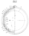
- Figure 1 shows a working with pressure stress-birefringent flat plate, the Lambda quarter plate in the deep ultraviolet range, e.g. with the excimer laser line 193 nm is useful.
- the faceplate is made of quartz glass for the Microlithography in the DUV of usually specified quality and has a thickness of only 6 mm.
- the thickness of the frame can be limited to approx. 12 mm.
- the shape of the quartz plate 1 is as the circle of the light beam 10 enveloping rectangular step shape, each step 11-19 has the same width, given symmetry to the x-axis and several (here 5) steps in the middle of the same distance from the y-axis are summarized.
- the second cover surface of the pressure shoes 41-49 is against one continuous elastic hydraulic hose 3, which with Hydraulic fluid 30, preferably distilled water, filled is and is supported against contact surfaces of the mounting ring 2. All second cover surfaces of the pressure shoes 41-49 are also the same size and completely covered by the hydraulic hose 3. The area is slightly smaller than and centered opposite the parallel top surfaces on steps 11-19 of the glass plate 1.
- the hydraulic fluid 30 is at a predetermined pressure acted upon, preferably as schematically in Figure 2 shown, via a cylinder 51 with piston 52, the Weight determines the pressure.
- a seal 53 avoids Dehydration.
- the precision of the faceplate 1 with levels 11-19 and the pressure shoes 41-49 thus determine the homogeneity of the Pressure load on the faceplate 1.
- the size of the pressure is unless vibration or shock effects occur - what in avoiding the surroundings of a microlithography system can be - just by the weight of the piston 52 and determined geometry parameters determined.
- a quartz glass plate 1 with a thickness of 6.00 mm achieves birefringence, which results in a phase shift of lambda / 4 at 193 nm, under a pressure in the plate plane of 1.618 N / mm 2 .
- Hydraulic hose 3 can be a commercially available hose from e.g. 6.5 mm diameter with 0.3 mm wall thickness made of butyl rubber Find use. With water as hydraulic fluid 30 there are no significant hazard potentials.
- the deflection of the quartz glass plate 1 when installed horizontally under its own weight is approximately 5 ⁇ m in the middle.
- the homogeneity of the birefringence in the quartz glass 1 can in Cross section 10 to less than 5% and less than 5 ° Angle deviation can be ensured.
- panels can be constructed similarly to those of described in DE 196 37 563 applied homogeneously with pressure become. When it comes to the construction, the main focus is on Avoid loading the glass plate with moments respect, think highly of. Suitable material combinations can also be used here thermosymmetric training can be achieved.
- Figure 3 shows a structure in which a square Quartz glass plate 1 'with the optically used cross section 10 the four sides of the rigid beams 61-64 are uniformly non-positive are attached.
- This assembly is via pressure balls 71, 72 and pressure pieces 81, 82 clamped in a frame 2 '. It is important that the bars 61-64 are much stiffer than the quartz plate 1 ', therefore they are preferably made of hard metal. The adhesion is achieved by material bonding, especially by soldering or gluing reached. The latter is with less critical UV radiation exposure suitable.
- the pressure pieces 81, 82 can be used as adjustable clamping means known types are trained and can also by suitable dimensioning and choice of materials thermosymmetrical design can be used.
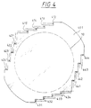
- FIG. 4 Another embodiment is shown in FIG. 4.
- the Force transmission into the (quartz glass) plate 401 none Cohesive connection required and the outer dimension the structure is closer to the effective diameter of the cross section 10 adjusted.
- the plate 1 has steps 411-414, 421-424, 431-434 and 441-444 on, in each case in the known from Figure 1 and 2 Art pressure is applied evenly. By number and width the steps 411-444 can be done in the required quality Approach to the introduction of the shear forces according to the figure Reach 3. All advantages of the construction according to Figures 1 and 2 can be so with the properties of the shear stress connect.
- the voltage birefringent according to the invention are preferably Plates designed as plane-parallel plates. To the Deflection can be prevented (under weight and tension) Radii are kept. However, the application is also for other plate shapes including prisms and lenses possible.
- the application in the DUV area, especially with microlithography optics and with measuring instruments is particularly important because there the usual inexpensive birefringent elements and Layers are not photochemically suitable.
Landscapes
- Physics & Mathematics (AREA)
- General Physics & Mathematics (AREA)
- Optics & Photonics (AREA)
- Engineering & Computer Science (AREA)
- Environmental & Geological Engineering (AREA)
- Health & Medical Sciences (AREA)
- Epidemiology (AREA)
- Public Health (AREA)
- Microelectronics & Electronic Packaging (AREA)
- Polarising Elements (AREA)
- Joining Of Glass To Other Materials (AREA)
- Mechanical Light Control Or Optical Switches (AREA)
- Exposure Of Semiconductors, Excluding Electron Or Ion Beam Exposure (AREA)
Abstract
Description
- Figur 1
- zeigt ein Ausführungsbeispiel mit abgestufter spannungsdoppelbrechender Platte und hydraulischer Druckeinleitung;
- Figur 2
- zeigt schematisch einen Ausschnitt aus Figur 1 und schematisch die Hydraulik;
- Figur 3
- zeigt eine Prinzipdarstellung einer Anordnung mit Schubspannung; und
- Figur 4
- zeigt ein Beispiel einer gestuften doppelbrechenden Platte für die Einleitung von Schubspannungen.
Claims (10)
- Doppelbrechende Plattenanordnung mit Spannungsdoppelbrechung, dadurch gekennzeichnet, daß an den Seiten der Platte (1) Druck- oder Schubvorrichtungen (41-49) angreifen.
- Doppelbrechende Plattenanordnung nach Anspruch 1, dadurch gekennzeichnet, daR die Platte (1) eine Planplatte ist.
- Doppelbrechende Plattenanordnung nach Anspruch 1 oder Anspruch 2, dadurch gekennzeichnet, daß die Platte (1) einen optischen Querschnitt (10) aufweist, der zur Transmission von Licht geeignet ist, und daß die Form der Platte (1) mittels Rechteckstufen (11-19) dem optischen Querschnitt (10) angenähert ist.
- Doppelbrechende Plattenanordnung nach Anspruch 3, dadurch gekennzeichnet, daß die Zahl der Rechteckstufen (11-19) 4 bis 25 beträgt.
- Doppelbrechende Plattenanordnung nach mindestens einem der Ansprüche 1-4, dadurch gekennzeichnet, daß eine hydraulische Druckübertragung (3, 51-53) vorgesehen ist.
- Doppelbrechende Plattenanordnung nach Anspruch 3 und Anspruch 5, dadurch gekennzeichnet, daß an jeder Rechteckstufe (11-19) beidseitig je mindestens ein Übertragungsschuh (41-49) angeordnet ist, der von der hydraulischen Druckübertragung (3) beaufschlagt ist.
- Doppelbrechende Plattenanordnung nach mindestens einem der Ansprüche 1-6, gekennzeichnet durch thermosymmetrische Konstruktion.
- Doppelbrechende Plattenanordnung nach mindestens einem der Ansprüche 1-7, dadurch gekennzeichnet, daß Schubspannungen in die Platte (1) eingebracht werden.
- Doppelbrechende Plattenanordnung nach mindestens einem der Ansprüche 5-8, dadurch gekennzeichnet, daß der Druck in der hydraulischen Druckübertragung durch ein Gewicht (52) erzeugt wird.
- Doppelbrechende Plattenanordnung nach mindestens einem der Ansprüche 5-9, dadurch gekennzeichnet, daß elastische Hüllen (3) für das Hydraulik-Medium (30) vorgesehen sind.
Applications Claiming Priority (2)
| Application Number | Priority Date | Filing Date | Title |
|---|---|---|---|
| DE19810089A DE19810089A1 (de) | 1998-03-10 | 1998-03-10 | Doppelbrechende Plattenanordnung mit Spannungsdoppelbrechung |
| DE19810089 | 1998-03-10 |
Publications (3)
| Publication Number | Publication Date |
|---|---|
| EP0942300A2 true EP0942300A2 (de) | 1999-09-15 |
| EP0942300A3 EP0942300A3 (de) | 2000-02-23 |
| EP0942300B1 EP0942300B1 (de) | 2004-07-28 |
Family
ID=7860237
Family Applications (1)
| Application Number | Title | Priority Date | Filing Date |
|---|---|---|---|
| EP99102483A Expired - Lifetime EP0942300B1 (de) | 1998-03-10 | 1999-02-10 | Doppelbrechende Plattenanordnung mit Spannungsdoppelbrechung |
Country Status (5)
| Country | Link |
|---|---|
| US (1) | US6141148A (de) |
| EP (1) | EP0942300B1 (de) |
| JP (1) | JPH11316346A (de) |
| KR (1) | KR19990077555A (de) |
| DE (2) | DE19810089A1 (de) |
Cited By (5)
| Publication number | Priority date | Publication date | Assignee | Title |
|---|---|---|---|---|
| WO2001050161A1 (en) * | 1999-12-23 | 2001-07-12 | Asml Us, Inc. | CALCIUM FLUORIDE (CaF2) STRESS PLATE AND METHOD OF MAKING THE SAME |
| EP1197764A3 (de) * | 2000-10-10 | 2003-11-26 | JDS Uniphase Corporation | Doppelbrechender Kristall mit Spannungsstabilisierung |
| EP1380896A1 (de) * | 2002-07-12 | 2004-01-14 | Schott Glas | Optisches System mit kompensierter Spatial Dispersion |
| US6816326B2 (en) | 2002-07-12 | 2004-11-09 | Schott Glas | Optical system with compensated spatial dispersion |
| US7408616B2 (en) | 2003-09-26 | 2008-08-05 | Carl Zeiss Smt Ag | Microlithographic exposure method as well as a projection exposure system for carrying out the method |
Families Citing this family (5)
| Publication number | Priority date | Publication date | Assignee | Title |
|---|---|---|---|---|
| JP3985346B2 (ja) | 1998-06-12 | 2007-10-03 | 株式会社ニコン | 投影露光装置、投影露光装置の調整方法、及び投影露光方法 |
| US6937394B2 (en) | 2001-04-10 | 2005-08-30 | Carl Zeiss Semiconductor Manufacturing Technologies Ag | Device and method for changing the stress-induced birefringence and/or the thickness of an optical component |
| AU2002354150A1 (en) * | 2001-12-10 | 2003-07-09 | Nikon Corporation | Fluoride crystal material for optical device used for photolithographic apparatus and its manufacturing method |
| US20070115551A1 (en) * | 2005-04-01 | 2007-05-24 | Alexis Spilman | Space-variant waveplate for polarization conversion, methods and applications |
| DE102007014587A1 (de) * | 2007-03-23 | 2008-09-25 | Carl Zeiss Smt Ag | Doppelbrechende Verzögerungsplattenanordnung |
Family Cites Families (11)
| Publication number | Priority date | Publication date | Assignee | Title |
|---|---|---|---|---|
| FR1174134A (fr) * | 1957-04-05 | 1959-03-06 | Procédé et dispositif permettant de transformer un faisceau de lumière blanche enun faisceau de lumière colorée de toute couleur désirée | |
| FR1485083A (fr) * | 1965-07-08 | 1967-06-16 | Ibm | Lames à retard de phase variable |
| US3600611A (en) * | 1970-03-18 | 1971-08-17 | Kettering Scient Research Inc | Elasto-optic device with mechanical bias |
| US3867014A (en) * | 1973-02-07 | 1975-02-18 | James C Kemp | Symmetric birefringence modulator |
| DE3002955A1 (de) * | 1980-01-29 | 1981-07-30 | Standard Elektrik Lorenz Ag, 7000 Stuttgart | Spannungsoptischer lichtmodulator |
| JPH0273215A (ja) * | 1988-09-09 | 1990-03-13 | Hitachi Ltd | 位相変調子 |
| JPH06296051A (ja) * | 1993-01-25 | 1994-10-21 | Sadao Nakai | 能動波長板 |
| DE4314574C2 (de) * | 1993-04-29 | 1997-04-10 | Leica Lithographie Systeme Jen | Verfahren zur Herstellung einer Stufenlinse vom fresnelschen Typ |
| US5625427A (en) * | 1993-12-15 | 1997-04-29 | Corning Incorporated | Ophthalmic lens |
| JP3044681B2 (ja) * | 1994-06-08 | 2000-05-22 | 富士写真フイルム株式会社 | 液晶表示装置 |
| JP3660402B2 (ja) * | 1995-08-23 | 2005-06-15 | 富士通株式会社 | 光フィルタ |
-
1998
- 1998-03-10 DE DE19810089A patent/DE19810089A1/de not_active Withdrawn
-
1999
- 1999-02-10 EP EP99102483A patent/EP0942300B1/de not_active Expired - Lifetime
- 1999-02-10 DE DE59910035T patent/DE59910035D1/de not_active Expired - Fee Related
- 1999-03-03 KR KR1019990006948A patent/KR19990077555A/ko not_active Abandoned
- 1999-03-08 US US09/265,524 patent/US6141148A/en not_active Expired - Fee Related
- 1999-03-09 JP JP11061665A patent/JPH11316346A/ja active Pending
Cited By (8)
| Publication number | Priority date | Publication date | Assignee | Title |
|---|---|---|---|---|
| WO2001050161A1 (en) * | 1999-12-23 | 2001-07-12 | Asml Us, Inc. | CALCIUM FLUORIDE (CaF2) STRESS PLATE AND METHOD OF MAKING THE SAME |
| US6324003B1 (en) | 1999-12-23 | 2001-11-27 | Silicon Valley Group, Inc. | Calcium fluoride (CaF2) stress plate and method of making the same |
| EP1197764A3 (de) * | 2000-10-10 | 2003-11-26 | JDS Uniphase Corporation | Doppelbrechender Kristall mit Spannungsstabilisierung |
| EP1380896A1 (de) * | 2002-07-12 | 2004-01-14 | Schott Glas | Optisches System mit kompensierter Spatial Dispersion |
| US6816326B2 (en) | 2002-07-12 | 2004-11-09 | Schott Glas | Optical system with compensated spatial dispersion |
| US7408616B2 (en) | 2003-09-26 | 2008-08-05 | Carl Zeiss Smt Ag | Microlithographic exposure method as well as a projection exposure system for carrying out the method |
| US7847921B2 (en) | 2003-09-26 | 2010-12-07 | Carl Zeiss Smt Ag | Microlithographic exposure method as well as a projection exposure system for carrying out the method |
| US8767181B2 (en) | 2003-09-26 | 2014-07-01 | Carl Zeiss Smt Gmbh | Microlithographic exposure method as well as a projection exposure system for carrying out the method |
Also Published As
| Publication number | Publication date |
|---|---|
| KR19990077555A (ko) | 1999-10-25 |
| DE19810089A1 (de) | 1999-09-16 |
| EP0942300A3 (de) | 2000-02-23 |
| US6141148A (en) | 2000-10-31 |
| JPH11316346A (ja) | 1999-11-16 |
| EP0942300B1 (de) | 2004-07-28 |
| DE59910035D1 (de) | 2004-09-02 |
Similar Documents
| Publication | Publication Date | Title |
|---|---|---|
| EP2158475B1 (de) | Wellenlängensensitiver optischer aufbau und dessen verwendung | |
| DE19637563A1 (de) | Doppelbrechende Planplattenanordnung und DUV-Viertelwellenplatte | |
| EP1444503B1 (de) | Verfahren und vorrichtung zum räumlich eng begrenzten anregen eines optischen übergangs | |
| EP0942300B1 (de) | Doppelbrechende Plattenanordnung mit Spannungsdoppelbrechung | |
| DE102008035224B4 (de) | Laseroszillator mit einer Befestigungskonstruktion für ein optisches Element | |
| DE69413583T2 (de) | Apparat zum Prüfen durch Vibration mit einem Öldrucklager | |
| DE19812021A1 (de) | Aktiver Spiegel | |
| EP1217450A2 (de) | Lichtintegrator für eine Beleuchtungseinrichtung | |
| EP2302432B1 (de) | Vorrichtung zur temperaturabhängigen axialen Verschiebung optischer Komponenten | |
| DE10259443B4 (de) | Verfahren und Anordnung zur optischen Untersuchung und/oder Bearbeitung einer Probe | |
| DE3829728A1 (de) | Verfahren und vorrichtung zum homogenisieren der intensitaetsverteilung im querschnit eines laserstrahls | |
| EP2606390A1 (de) | Mehrstufig justierbare fassungsbaugruppe für zwei optische bauteile | |
| DE2435422C2 (de) | Flüssigkristallzelle | |
| DE3732566C2 (de) | ||
| EP1245983A2 (de) | Vorrichtung zur Justierung von Einrichtungen und zum Einstellen von Verstellwegen | |
| WO2003087944A2 (de) | Vorrichtung zur deformationsarmen lagerung eines nicht rotationssymmetrischen optischen elementes | |
| EP1395859B1 (de) | Laserjustierbarer Aktor, optisches Bauelement und Justierverfahren | |
| DE2946175C2 (de) | ||
| DE29711362U1 (de) | Vorrichtung zum Einspannen und Prüfen von Prüfkörpern | |
| DE102017126291A1 (de) | Vorrichtung zur Erzeugung einer Laserstrahlung | |
| DE3840261A1 (de) | Belastungsvorrichtung | |
| DE102013114822B3 (de) | Zweiachsige Kippvorrichtung | |
| DE4219177C2 (de) | Gehäuseeinspannung für einen Sensor | |
| DE3905508C2 (de) | ||
| DE102006022957A1 (de) | Optische Vorrichtung mit einem optischen Bauelement und mit einer Verstelleinrichtung und Verfahren zur Beeinflussung eines Polarisationszustands des optischen Bauelements |
Legal Events
| Date | Code | Title | Description |
|---|---|---|---|
| PUAI | Public reference made under article 153(3) epc to a published international application that has entered the european phase |
Free format text: ORIGINAL CODE: 0009012 |
|
| AK | Designated contracting states |
Kind code of ref document: A2 Designated state(s): DE FR GB IE IT NL |
|
| AX | Request for extension of the european patent |
Free format text: AL;LT;LV;MK;RO;SI |
|
| PUAL | Search report despatched |
Free format text: ORIGINAL CODE: 0009013 |
|
| AK | Designated contracting states |
Kind code of ref document: A3 Designated state(s): AT BE CH CY DE DK ES FI FR GB GR IE IT LI LU MC NL PT SE |
|
| AX | Request for extension of the european patent |
Free format text: AL;LT;LV;MK;RO;SI |
|
| RIC1 | Information provided on ipc code assigned before grant |
Free format text: 7G 02B 5/30 A, 7G 02F 1/01 B |
|
| 17P | Request for examination filed |
Effective date: 20000725 |
|
| AKX | Designation fees paid |
Free format text: DE FR GB IE IT NL |
|
| 17Q | First examination report despatched |
Effective date: 20030903 |
|
| GRAP | Despatch of communication of intention to grant a patent |
Free format text: ORIGINAL CODE: EPIDOSNIGR1 |
|
| RAP1 | Party data changed (applicant data changed or rights of an application transferred) |
Owner name: CARL-ZEISS-STIFTUNG, TRADING AS CARL ZEISS Owner name: CARL ZEISS |
|
| RAP1 | Party data changed (applicant data changed or rights of an application transferred) |
Owner name: CARL-ZEISS-STIFTUNG TRADING AS CARL ZEISS Owner name: CARL ZEISS |
|
| RIC1 | Information provided on ipc code assigned before grant |
Ipc: 7G 02F 1/01 A |
|
| GRAS | Grant fee paid |
Free format text: ORIGINAL CODE: EPIDOSNIGR3 |
|
| GRAA | (expected) grant |
Free format text: ORIGINAL CODE: 0009210 |
|
| AK | Designated contracting states |
Kind code of ref document: B1 Designated state(s): DE FR GB IE IT NL |
|
| PG25 | Lapsed in a contracting state [announced via postgrant information from national office to epo] |
Ref country code: IT Free format text: LAPSE BECAUSE OF FAILURE TO SUBMIT A TRANSLATION OF THE DESCRIPTION OR TO PAY THE FEE WITHIN THE PRESCRIBED TIME-LIMIT;WARNING: LAPSES OF ITALIAN PATENTS WITH EFFECTIVE DATE BEFORE 2007 MAY HAVE OCCURRED AT ANY TIME BEFORE 2007. THE CORRECT EFFECTIVE DATE MAY BE DIFFERENT FROM THE ONE RECORDED. Effective date: 20040728 Ref country code: IE Free format text: LAPSE BECAUSE OF FAILURE TO SUBMIT A TRANSLATION OF THE DESCRIPTION OR TO PAY THE FEE WITHIN THE PRESCRIBED TIME-LIMIT Effective date: 20040728 Ref country code: GB Free format text: LAPSE BECAUSE OF FAILURE TO SUBMIT A TRANSLATION OF THE DESCRIPTION OR TO PAY THE FEE WITHIN THE PRESCRIBED TIME-LIMIT Effective date: 20040728 Ref country code: FR Free format text: LAPSE BECAUSE OF FAILURE TO SUBMIT A TRANSLATION OF THE DESCRIPTION OR TO PAY THE FEE WITHIN THE PRESCRIBED TIME-LIMIT Effective date: 20040728 |
|
| RAP1 | Party data changed (applicant data changed or rights of an application transferred) |
Owner name: CARL ZEISS SMT AG |
|
| REG | Reference to a national code |
Ref country code: GB Ref legal event code: FG4D Free format text: NOT ENGLISH |
|
| REG | Reference to a national code |
Ref country code: IE Ref legal event code: FG4D Free format text: GERMAN |
|
| REF | Corresponds to: |
Ref document number: 59910035 Country of ref document: DE Date of ref document: 20040902 Kind code of ref document: P |
|
| GBV | Gb: ep patent (uk) treated as always having been void in accordance with gb section 77(7)/1977 [no translation filed] |
Effective date: 20040728 |
|
| REG | Reference to a national code |
Ref country code: IE Ref legal event code: FD4D |
|
| PLBE | No opposition filed within time limit |
Free format text: ORIGINAL CODE: 0009261 |
|
| STAA | Information on the status of an ep patent application or granted ep patent |
Free format text: STATUS: NO OPPOSITION FILED WITHIN TIME LIMIT |
|
| 26N | No opposition filed |
Effective date: 20050429 |
|
| EN | Fr: translation not filed | ||
| PGFP | Annual fee paid to national office [announced via postgrant information from national office to epo] |
Ref country code: DE Payment date: 20060214 Year of fee payment: 8 |
|
| PGFP | Annual fee paid to national office [announced via postgrant information from national office to epo] |
Ref country code: NL Payment date: 20060215 Year of fee payment: 8 |
|
| NLV4 | Nl: lapsed or anulled due to non-payment of the annual fee |
Effective date: 20070901 |
|
| PG25 | Lapsed in a contracting state [announced via postgrant information from national office to epo] |
Ref country code: NL Free format text: LAPSE BECAUSE OF NON-PAYMENT OF DUE FEES Effective date: 20070901 Ref country code: DE Free format text: LAPSE BECAUSE OF NON-PAYMENT OF DUE FEES Effective date: 20070901 |