EP0942293B1 - Dispositif de mesure de distances ou de l'angle d'incidence d'un faisceau lumineux - Google Patents
Dispositif de mesure de distances ou de l'angle d'incidence d'un faisceau lumineux Download PDFInfo
- Publication number
- EP0942293B1 EP0942293B1 EP98811242A EP98811242A EP0942293B1 EP 0942293 B1 EP0942293 B1 EP 0942293B1 EP 98811242 A EP98811242 A EP 98811242A EP 98811242 A EP98811242 A EP 98811242A EP 0942293 B1 EP0942293 B1 EP 0942293B1
- Authority
- EP
- European Patent Office
- Prior art keywords
- optical
- prism
- position detector
- receiving system
- light beam
- Prior art date
- Legal status (The legal status is an assumption and is not a legal conclusion. Google has not performed a legal analysis and makes no representation as to the accuracy of the status listed.)
- Expired - Lifetime
Links
Images


Classifications
-
- G—PHYSICS
- G01—MEASURING; TESTING
- G01S—RADIO DIRECTION-FINDING; RADIO NAVIGATION; DETERMINING DISTANCE OR VELOCITY BY USE OF RADIO WAVES; LOCATING OR PRESENCE-DETECTING BY USE OF THE REFLECTION OR RERADIATION OF RADIO WAVES; ANALOGOUS ARRANGEMENTS USING OTHER WAVES
- G01S17/00—Systems using the reflection or reradiation of electromagnetic waves other than radio waves, e.g. lidar systems
- G01S17/02—Systems using the reflection of electromagnetic waves other than radio waves
- G01S17/06—Systems determining position data of a target
- G01S17/46—Indirect determination of position data
- G01S17/48—Active triangulation systems, i.e. using the transmission and reflection of electromagnetic waves other than radio waves
-
- G—PHYSICS
- G01—MEASURING; TESTING
- G01S—RADIO DIRECTION-FINDING; RADIO NAVIGATION; DETERMINING DISTANCE OR VELOCITY BY USE OF RADIO WAVES; LOCATING OR PRESENCE-DETECTING BY USE OF THE REFLECTION OR RERADIATION OF RADIO WAVES; ANALOGOUS ARRANGEMENTS USING OTHER WAVES
- G01S7/00—Details of systems according to groups G01S13/00, G01S15/00, G01S17/00
- G01S7/48—Details of systems according to groups G01S13/00, G01S15/00, G01S17/00 of systems according to group G01S17/00
- G01S7/481—Constructional features, e.g. arrangements of optical elements
- G01S7/4816—Constructional features, e.g. arrangements of optical elements of receivers alone
Definitions
- the present invention relates to a device for measuring distances or angle of incidence of a light beam according to the preamble of claim 1.
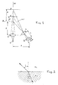
- angle of attack or distance measurements by optoelectronic systems are based on the triangulation principle described in figure 1.
- a second disadvantage namely the severe limitation of the range of measurement resulting in a large dead zone Z.
- EP-A-458 752 by the same applicant describes a measurement method an angle of incidence comprising a birefringent blade of variable thickness in the form of a prism to make appear, in polarized light only, a succession interference fringes whose position is determined by the beam angle and the thickness of the blade.
- the invention aims the creation of a distance measuring device or of an angle of incidence of a light beam, having a restricted base, i.e. a reduced footprint by compared to known devices and a longer measuring range important.
- Figure 1 which schematically represents the principle of a distance measurement by known triangulation, we recognizes the light source 1 and the emission optics which projects the beam from the light source onto the object to be measured 3 and 3 'which is at a distance d, respectively from a reference surface.
- the light diffusely reflected by the object to be measured is collected in a reception lens or a reception optic 4 and projected onto a position detector 5 located at a distance C from said receiving lens or optic 4.
- the distance b from the reference R of the position detector depends on the distance to be measured d.
- the basic idea of the present invention is to compress or amplify non-linearly the variation angle of light in reception optics.
- the realization of this inventive idea provides a compact detector with a large measuring range while reconciling the reception optics and the transmission optics.
- ⁇ r means the variation of the angle of refraction and ⁇ i the variation of the angle of incidence.
- Figure 3 shows very schematically the source of light 6, the emission optics 7 with the optical axis AO and the object to be measured 8 at a certain distance d from the source and object 9 shown in dotted lines at a distance reduced from which corresponds to a reduced dead zone.
- Figure 3 shows a variation between the incident beam i coming from object 8 located at the greatest distance d and the beam of incidence i 'coming from the object 9 located at the shorter distance of, i.e. a falling ⁇ i of 40 ° on the input face 10 of the prism 11, which produces a variation of the ⁇ r beam by 20 ° at the exit of the prism. it means that the measuring range of detector 12 is large and the small dead zone despite a small gap between the light source and position detector.
- Figure 3 also shows that the lens 13 which focuses the beam coming out of the prism on the position sensor can be integrated into the prism.
- Figures 4 and 5 show two exemplary embodiments a sensor, i.e. an optoelectronic assembly with a light source and a position detector.
- the Figure 4 is a schematic drawing showing on the left a transmitter system and on the right a receiver system, with the light source 6 in a housing 14 comprising means known (not shown) for holding and adjusting the source luminous and comprising bearings 15 blackened inside to generate as little reflection as possible.
- the optical system 7 projecting the light from light source 6 on the object to be measured, which is not shown.
- the optical axis AO is drawn in line batchwise. Towards the outside the case is closed by a optical window 16.
- the receiver system is integrated in the same box, which is closed to the outside by an optical window 17.
- the incident beam i 'from the object to be measured the most close together is about 40 ° to the optical axis AO and falls on the entry face 10 of the prism 11. This face input 10 is cut at around 45 ° to the axis optics AO '.
- the outgoing refracted beam then falls on a mirror 19 returning the beam to the position detector 12.
- the incident beam i coming from the position of the object at measure the farthest is refracted by the input face 10 of the prism and becomes the refracted beam r passing through also the lens 13 and falling on the mirror 19, from where it is returned to the position detector 12.
- the measuring device is located in a box and includes the position sensor and the circuits measurement and control known to those skilled in the art.
- the construction according to Figure 4 allows for a sensor reduced in size compared to a sensor according to the art prior.
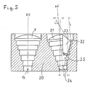
- the manufacturing example according to FIG. 5 allows further increase the detection distance and obtain a large measuring range with compact construction and reduced dimensions.
- the transmitting system and the system receiver are placed side by side in the same box 20.
- the transmitter system includes a source light 6 and a focusing lens 7 projecting the light on the object to be measured not shown.
- the system of reception consists of the association of a prism with focusing lens, as described in the example previous, and a lens or lens portion focusing the reflected light on the same detector position.
- the lens 21 When the reflected light falls at an angle included between -6 ° and 0 ° relative to the optical axis, the lens 21 focuses these beams on the position detector 24 between points -6 and 0.
- the beams i and i 'incidents are refracted by the input face 23 of the prism 22 and then focused by lens 25 on the position detector 24 located at right angles to relative to the optical axis.
- the refracted rays r and r ' are focused on the detector between the point O located exactly in the optical axis of the system and point 30 towards the end of the detector.
- the nonlinear angular compression produced by the prism lowers the angular sensitivity of the measurement when the distance to be measured decreases.
- the amount of light collected by the prism also decreases when the distance from measure decreases because more is then reflected outward from the entrance face of the prism. This is also a favorable parameter which tends to avoid the saturation of the measuring device.
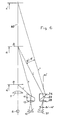
- the diagram of FIG. 6 includes that of FIG. 3 and in plus the arrangement for beam expansion.
- the prism 26 is located in such a way that the face inclined by relative to the optical axis AO '', which is parallel to the axis AO optics of the receiving optics, is the output face 29.
- the outlet face 29 can form an angle of about 40 ° with the optical axis AO ''.
- Figure 6 shows a variation between the incident beam i coming from object 8 located at the mean distance d and the incident beam i '' coming from the object located at the greatest distance from 'with an ⁇ i' of 8 ° falling on the prism 26 to produce a variation of the beam ⁇ r 'of 16 ° on the detector 27, at the outlet of the prism.
- Figure 6 allows make detectors measuring at long distance with a large measuring range, by combining an expanding optic angular or classic optics for long distance and angular compression optics for the area close.
- the manufacturing example described in Figure 7 shows the realization of a sensor combining the advantages of angular compression by prism 11 for measurements close together and angular expansion through the prism 26 for distant measurements.
- the transmitter system and receiver systems with two prisms are integrated side by side in the same box 31 and the construction is made very compact by using the same mirror spherical 30 to replace lens 13 or 25 and the lens 28, focusing the incident beams on the position sensors 12 or 24 for near measurements and 27 for distant measurements. It is possible to replace the only spherical mirror by two spherical mirrors, one for each prism. It is conceivable to provide only one detector instead of two detectors 12 or 24 and 27.
Description
- La figure 1
- montre schématiquement le principe de mesure de triangulation,
- la figure 2
- décrit la loi de Snell-Descartes,
- la figure 3
- montre le principe de mesure selon l'invention,
- la figure 4
- montre une première forme d'exécution d'un dispositif selon l'invention,
- la figure 5
- montre une deuxième forme d'exécution de l'invention,
- la figure 6
- montre un principe de mesure plus ample par rapport à celui de la figure 3, et
- la figure 7
- montre une autre forme d'exécution d'un dispositif selon l'invention.
Claims (10)
- Dispositif de mesure de distances ou de l'angle d'incidence d'un faisceau lumineux, comprenant une optique d'émission (7) pour projeter le faisceau lumineux sur l'objet à mesurer et une optique de réception (11, 13; 21, 22, 25) pour projeter la lumière réfléchie sur un détecteur de position, caractérisé en ce que l'optique de réception (11, 13; 21, 22, 25; 30) comprend un prisme (11, 22) réfractant le faisceau lumineux avec une compression des variations angulaires permettant de réduire l'étendue du détecteur de position (12, 24) nécessaire pour mesurer une plage de mesure correspondante.
- Dispositif de mesure de distances ou de l'angle d'incidence d'un faisceau lumineux comprenant une optique d'émission (7) pour projeter le faisceau lumineux sur l'objet à mesurer et une optique de réception (26, 28, 29; 30) pour projeter la lumière réfléchie sur un détecteur de position, caractérisé en ce que l'optique de réception comprend comme premier. élément un prisme (26) réfractant le faisceau lumineux avec une expansion des variations angulaires permettant d'augmenter la sensibilité du détecteur de position (27) pour les faibles variations angulaires.
- Dispositif selon la revendication 1, caractérisé en ce que la face d'entrée (10, 23) du prisme (11, 22) forme un angle d'environ 45° avec l'axe optique (AO') de l'optique de réception.
- Dispositif selon la revendication 2, caractérisé en ce que la face de sortie (29) du prisme (26) forme un angle d'environ 40° avec l'axe optique (AO) de l'optique de réception.
- Dispositif selon l'une des revendications 1 à 4, caractérisé en ce que la face de sortie du prisme comprend des éléments optique (13, 25; 28; 30) pour projeter le faisceau réfracté sur le détecteur de position (12, 24, 27).
- Dispositif selon la revendication 5, caractérisé en ce que les éléments optiques à la face de sortie du premier prisme (11) et à la face de sortie (29) du deuxième prisme (26) sont constitués par un seul miroir sphérique (30) ou par deux miroirs sphérique focalisant les faisceaux diffractés sur le(s) détecteur(s) de position (12, 24, 27).
- Dispositif selon l'une des revendications 1, 3, 5 ou 6, caractérisé en ce que l'optique de réception, comprenant le prisme (11), est séparé de l'optique d'émission et comprend un miroir (19) agencé sous la face de sortie du prisme avec les éléments optique (13) pour projeter le faisceau réfracté sur le détecteur de position (12) agencé parallèlement à l'axe optique (AO'), l'optique d'émission et l'optique de réception formant un capteur agencé dans un boítier (14).
- Dispositif selon l'une des revendications 1, 3, 5 ou 6, caractérisé en ce que l'optique de réception (21; 22, 25) comprend l'association du prisme (22) avec une lentille de focalisation (25) et d'une lentille ou portion de lentille (21) de focalisation, chacun de ces éléments étant conçu pour recevoir la lumière réfléchie et pour projeter cette lumière réfléchie sur le détecteur de position (24) selon l'angle formé par le faisceau avec l'axe optique (AO') du système optique de réception.
- Dispositif selon la revendication 8, caractérisé en ce que le détecteur de position (24) est orienté à 90° par rapport à l'axe optique (AO') de l'optique de réception.
- Dispositif selon l'une des revendications 1 à 9, caractérisé par un assemblage regroupant l'optique d'émission (7) avec l'optique de réception (11, 13, 21, 22, 25, 30) réfractant le faisceau lumineux avec une compression et l'optique de réception (26, 28, 29, 30) réfractant le faisceau lumineux avec une expansion des variations angulaires ainsi que le(s) détecteur(s) de position (12, 24; 27) dans un boítier (31).
Priority Applications (4)
| Application Number | Priority Date | Filing Date | Title |
|---|---|---|---|
| EP98811242A EP0942293B1 (fr) | 1998-02-10 | 1998-12-17 | Dispositif de mesure de distances ou de l'angle d'incidence d'un faisceau lumineux |
| US09/240,698 US6133988A (en) | 1998-02-10 | 1999-02-02 | Device for the measurement of distances or of the angle of incidence of a light beam |
| CA002261332A CA2261332A1 (fr) | 1998-02-10 | 1999-02-09 | Dispositif de mesure de distance ou d'angle d'incidence de faisceaux lumineux |
| JP03114599A JP4370012B2 (ja) | 1998-02-10 | 1999-02-09 | 距離または光線の入射角度測定装置 |
Applications Claiming Priority (3)
| Application Number | Priority Date | Filing Date | Title |
|---|---|---|---|
| EP98810102 | 1998-02-10 | ||
| EP98810102 | 1998-02-10 | ||
| EP98811242A EP0942293B1 (fr) | 1998-02-10 | 1998-12-17 | Dispositif de mesure de distances ou de l'angle d'incidence d'un faisceau lumineux |
Publications (3)
| Publication Number | Publication Date |
|---|---|
| EP0942293A2 EP0942293A2 (fr) | 1999-09-15 |
| EP0942293A3 EP0942293A3 (fr) | 2000-01-19 |
| EP0942293B1 true EP0942293B1 (fr) | 2002-05-29 |
Family
ID=26151866
Family Applications (1)
| Application Number | Title | Priority Date | Filing Date |
|---|---|---|---|
| EP98811242A Expired - Lifetime EP0942293B1 (fr) | 1998-02-10 | 1998-12-17 | Dispositif de mesure de distances ou de l'angle d'incidence d'un faisceau lumineux |
Country Status (4)
| Country | Link |
|---|---|
| US (1) | US6133988A (fr) |
| EP (1) | EP0942293B1 (fr) |
| JP (1) | JP4370012B2 (fr) |
| CA (1) | CA2261332A1 (fr) |
Families Citing this family (19)
| Publication number | Priority date | Publication date | Assignee | Title |
|---|---|---|---|---|
| SE522366C2 (sv) * | 1999-02-26 | 2004-02-03 | Latronix Ab | Avståndsmätare |
| DE10011046A1 (de) * | 2000-03-07 | 2001-10-04 | Omron Electronics Mfg Of Germa | Verfahren zum Erfassen von Abständen von Objekten mittels eines Triangulations-Sensors und Triangulations-Sensor zum Durchführen des Verfahrens |
| US6369879B1 (en) * | 2000-10-24 | 2002-04-09 | The Regents Of The University Of California | Method and apparatus for determining the coordinates of an object |
| JP2003035534A (ja) * | 2001-07-25 | 2003-02-07 | Sumitomo Osaka Cement Co Ltd | 距離センサ、距離センサアレイ |
| DE10214280A1 (de) * | 2002-03-28 | 2003-10-16 | Bosch Gmbh Robert | Vorrichtung zur optischen Distanzmessung |
| DE10220037C5 (de) * | 2002-05-04 | 2011-02-24 | Sick Ag | Vorrichtung zum Detektieren von Objekten |
| DE10305861A1 (de) * | 2003-02-13 | 2004-08-26 | Adam Opel Ag | Vorrichtung eines Kraftfahrzeuges zur räumlichen Erfassung einer Szene innerhalb und/oder außerhalb des Kraftfahrzeuges |
| DE10331074A1 (de) * | 2003-07-09 | 2005-02-03 | Conti Temic Microelectronic Gmbh | Sensoranordnung zur Abstands- und/oder Geschwindigkeitsmessung |
| DE102005045280B3 (de) * | 2005-09-22 | 2006-12-28 | Leuze Electronic Gmbh & Co Kg | Distanzsensor |
| DE102006013292A1 (de) * | 2006-03-23 | 2007-09-27 | Robert Bosch Gmbh | Vorrichtung zur optischen Distanzmessung |
| US20100133424A1 (en) * | 2007-05-26 | 2010-06-03 | Norman Matheson Lindsay | Electro-optical sensors |
| DE102009047662A1 (de) | 2009-12-08 | 2011-06-09 | Endress + Hauser Gmbh + Co. Kg | Nach dem Triangulationsprinzip arbeitende Vorrichtung zur optischen Entfernungsmessung |
| DE102010040051A1 (de) | 2010-08-31 | 2012-03-01 | Balluff Gmbh | Lichtschrankenvorrichtung |
| CN103477242B (zh) * | 2011-04-15 | 2015-08-12 | 欧司朗光电半导体有限公司 | 光电子装置 |
| DE102014114314A1 (de) | 2014-10-01 | 2016-04-07 | Sick Ag | Optoelektronischer Sensor |
| DE102014116254A1 (de) * | 2014-11-07 | 2016-05-12 | Sick Ag | Sensor |
| TW201804131A (zh) * | 2016-07-20 | 2018-02-01 | 陳進益 | 雙鏡頭與曲面光碟共構的行動測距裝置 |
| KR20190051409A (ko) * | 2017-11-07 | 2019-05-15 | 주식회사 엘지화학 | 시트 및 광학식 지문 인식 장치 |
| CN111522135B (zh) * | 2020-03-20 | 2022-02-11 | 北京国泰蓝盾科技有限公司 | 一种适用于三角测量的大孔径折反镜头 |
Family Cites Families (4)
| Publication number | Priority date | Publication date | Assignee | Title |
|---|---|---|---|---|
| JPS63235909A (ja) * | 1987-03-24 | 1988-09-30 | Fuji Photo Optical Co Ltd | アクテイブ型オ−トフオ−カス機構 |
| US4872747A (en) * | 1987-04-15 | 1989-10-10 | Cyberoptics Corporation | Use of prisms to obtain anamorphic magnification |
| JPS6465460A (en) * | 1987-09-07 | 1989-03-10 | Hitachi Ltd | Space filter type speed measuring instrument |
| CH683381A5 (fr) * | 1990-05-23 | 1994-02-28 | Charles Rheme | Procédé de mesure d'un angle d'incidence d'un faisceau lumineux, dispositif de mesure pour la mise en oeuvre du procédé et utilisation du dispositif pour la mesure de distances. |
-
1998
- 1998-12-17 EP EP98811242A patent/EP0942293B1/fr not_active Expired - Lifetime
-
1999
- 1999-02-02 US US09/240,698 patent/US6133988A/en not_active Expired - Lifetime
- 1999-02-09 CA CA002261332A patent/CA2261332A1/fr not_active Abandoned
- 1999-02-09 JP JP03114599A patent/JP4370012B2/ja not_active Expired - Lifetime
Also Published As
| Publication number | Publication date |
|---|---|
| EP0942293A3 (fr) | 2000-01-19 |
| US6133988A (en) | 2000-10-17 |
| JP4370012B2 (ja) | 2009-11-25 |
| EP0942293A2 (fr) | 1999-09-15 |
| CA2261332A1 (fr) | 1999-08-10 |
| JP2000065566A (ja) | 2000-03-03 |
Similar Documents
| Publication | Publication Date | Title |
|---|---|---|
| EP0942293B1 (fr) | Dispositif de mesure de distances ou de l'angle d'incidence d'un faisceau lumineux | |
| WO2002095475A1 (fr) | Procede et dispostif de mesure par imagerie confocale a chromatisme entendu | |
| FR2490433A1 (fr) | Systeme de transmission a l'aide d'une fibre optique | |
| CA2045244A1 (fr) | Dispositif de mesure de parametres meteorologiques | |
| FR2495315A1 (fr) | Dispositif de mesure a fibres optiques | |
| EP0846274B1 (fr) | Sonde velocimetrique optique | |
| CA2220940C (fr) | Dispositif pour determiner les defauts de phase d'ondes electromagnetiques | |
| FR2498318A1 (fr) | Appareil combine de mesure de vitesse et de dimension | |
| FR2848664A1 (fr) | Detecteur de position, forme et reflectivite d'une surface | |
| WO1993020416A1 (fr) | Dispositif optique du type deflectometre, notamment a detection de phase, a grand domaine de mesure | |
| FR3084158A1 (fr) | Methode et dispositif de caracterisation de filtres optiques | |
| CA2405956C (fr) | Dispositif d'acquisition d'une forme tridimensionnelle par voie optoelectronique | |
| FR2761162A1 (fr) | Dispositif de mesure de vitesse a effet doppler, notamment pour engins volants | |
| EP0448415B1 (fr) | Dispositif de détection à distance d'une grandeur physique, fonctionnant en réflexion | |
| EP1019688A1 (fr) | Appareil de mesure de la longueur d'onde d'un faisceau lumineux | |
| EP0287448A1 (fr) | Procédé et dispositif de mesure par réflexion du coefficient de transmission optique d'une paroi vitreuse teintée | |
| EP0911645B1 (fr) | Dispositif optique à modulation de polarisation pour la mesure de distance et/ou de vitesse d'objet | |
| FR2649493A1 (fr) | Capteur optique pour l'identification et la detection directionnelle de rayonnements optiques | |
| FR2567651A1 (fr) | Equipement de mesure de vitesse d'un projectile par interferometrie utilisant un faisceau laser propage par un guide d'onde optique unique | |
| FR2710146A1 (fr) | Dispositif optique de mesure d'écart transversal. | |
| FR2728971A1 (fr) | Telemetre discret multifonctionnel | |
| FR3071069B1 (fr) | Dispositif de telemetrie laser monostatique | |
| FR2844603A3 (fr) | Dispositif de couplage par fibre optique d'un systeme emetteur recepteur optique | |
| FR3064058A1 (fr) | Systeme optique et spectrometre miniature equipe d'un tel systeme ainsi que procede d'analyse d'objets a l'aide d'un tel systeme optique | |
| FR3121758A1 (fr) | Télescope bi-spectral catadioptrique |
Legal Events
| Date | Code | Title | Description |
|---|---|---|---|
| PUAI | Public reference made under article 153(3) epc to a published international application that has entered the european phase |
Free format text: ORIGINAL CODE: 0009012 |
|
| AK | Designated contracting states |
Kind code of ref document: A2 Designated state(s): AT BE CH DE ES FR GB IT LI NL SE |
|
| AX | Request for extension of the european patent |
Free format text: AL;LT;LV;MK;RO;SI |
|
| PUAL | Search report despatched |
Free format text: ORIGINAL CODE: 0009013 |
|
| RIC1 | Information provided on ipc code assigned before grant |
Free format text: 7G 01S 17/46 A, 7G 01S 7/481 B |
|
| AK | Designated contracting states |
Kind code of ref document: A3 Designated state(s): AT BE CH CY DE DK ES FI FR GB GR IE IT LI LU MC NL PT SE |
|
| AX | Request for extension of the european patent |
Free format text: AL;LT;LV;MK;RO;SI |
|
| 17P | Request for examination filed |
Effective date: 20000219 |
|
| RIN1 | Information on inventor provided before grant (corrected) |
Inventor name: HEIMLICHER, PETER Inventor name: RHEME, CHARLES |
|
| K1C3 | Correction of patent application (complete document) published |
Effective date: 20000119 |
|
| AKX | Designation fees paid |
Free format text: AT BE CH DE ES FR GB IT LI NL SE |
|
| 17Q | First examination report despatched |
Effective date: 20000927 |
|
| GRAG | Despatch of communication of intention to grant |
Free format text: ORIGINAL CODE: EPIDOS AGRA |
|
| GRAG | Despatch of communication of intention to grant |
Free format text: ORIGINAL CODE: EPIDOS AGRA |
|
| GRAH | Despatch of communication of intention to grant a patent |
Free format text: ORIGINAL CODE: EPIDOS IGRA |
|
| GRAH | Despatch of communication of intention to grant a patent |
Free format text: ORIGINAL CODE: EPIDOS IGRA |
|
| GRAA | (expected) grant |
Free format text: ORIGINAL CODE: 0009210 |
|
| AK | Designated contracting states |
Kind code of ref document: B1 Designated state(s): AT BE CH DE ES FR GB IT LI NL SE |
|
| PG25 | Lapsed in a contracting state [announced via postgrant information from national office to epo] |
Ref country code: NL Free format text: LAPSE BECAUSE OF FAILURE TO SUBMIT A TRANSLATION OF THE DESCRIPTION OR TO PAY THE FEE WITHIN THE PRESCRIBED TIME-LIMIT Effective date: 20020529 Ref country code: AT Free format text: LAPSE BECAUSE OF FAILURE TO SUBMIT A TRANSLATION OF THE DESCRIPTION OR TO PAY THE FEE WITHIN THE PRESCRIBED TIME-LIMIT Effective date: 20020529 |
|
| REF | Corresponds to: |
Ref document number: 218210 Country of ref document: AT Date of ref document: 20020615 Kind code of ref document: T |
|
| REG | Reference to a national code |
Ref country code: GB Ref legal event code: FG4D Free format text: NOT ENGLISH |
|
| REG | Reference to a national code |
Ref country code: CH Ref legal event code: NV Representative=s name: AMMANN PATENTANWAELTE AG BERN Ref country code: CH Ref legal event code: EP |
|
| REF | Corresponds to: |
Ref document number: 69805598 Country of ref document: DE Date of ref document: 20020704 |
|
| GBT | Gb: translation of ep patent filed (gb section 77(6)(a)/1977) |
Effective date: 20020720 |
|
| PG25 | Lapsed in a contracting state [announced via postgrant information from national office to epo] |
Ref country code: SE Free format text: LAPSE BECAUSE OF FAILURE TO SUBMIT A TRANSLATION OF THE DESCRIPTION OR TO PAY THE FEE WITHIN THE PRESCRIBED TIME-LIMIT Effective date: 20020829 |
|
| NLV1 | Nl: lapsed or annulled due to failure to fulfill the requirements of art. 29p and 29m of the patents act | ||
| PG25 | Lapsed in a contracting state [announced via postgrant information from national office to epo] |
Ref country code: ES Free format text: LAPSE BECAUSE OF FAILURE TO SUBMIT A TRANSLATION OF THE DESCRIPTION OR TO PAY THE FEE WITHIN THE PRESCRIBED TIME-LIMIT Effective date: 20021128 |
|
| PG25 | Lapsed in a contracting state [announced via postgrant information from national office to epo] |
Ref country code: BE Free format text: LAPSE BECAUSE OF NON-PAYMENT OF DUE FEES Effective date: 20021231 |
|
| PLBE | No opposition filed within time limit |
Free format text: ORIGINAL CODE: 0009261 |
|
| STAA | Information on the status of an ep patent application or granted ep patent |
Free format text: STATUS: NO OPPOSITION FILED WITHIN TIME LIMIT |
|
| 26N | No opposition filed |
Effective date: 20030303 |
|
| BERE | Be: lapsed |
Owner name: S.A. *OPTOSYS Effective date: 20021231 |
|
| REG | Reference to a national code |
Ref country code: FR Ref legal event code: PLFP Year of fee payment: 18 |
|
| REG | Reference to a national code |
Ref country code: FR Ref legal event code: PLFP Year of fee payment: 19 |
|
| REG | Reference to a national code |
Ref country code: FR Ref legal event code: PLFP Year of fee payment: 20 |
|
| PGFP | Annual fee paid to national office [announced via postgrant information from national office to epo] |
Ref country code: DE Payment date: 20171211 Year of fee payment: 20 Ref country code: FR Payment date: 20171221 Year of fee payment: 20 |
|
| PGFP | Annual fee paid to national office [announced via postgrant information from national office to epo] |
Ref country code: CH Payment date: 20171221 Year of fee payment: 20 Ref country code: GB Payment date: 20171221 Year of fee payment: 20 |
|
| PGFP | Annual fee paid to national office [announced via postgrant information from national office to epo] |
Ref country code: IT Payment date: 20171221 Year of fee payment: 20 |
|
| REG | Reference to a national code |
Ref country code: DE Ref legal event code: R071 Ref document number: 69805598 Country of ref document: DE |
|
| REG | Reference to a national code |
Ref country code: CH Ref legal event code: PL |
|
| REG | Reference to a national code |
Ref country code: GB Ref legal event code: PE20 Expiry date: 20181216 |
|
| PG25 | Lapsed in a contracting state [announced via postgrant information from national office to epo] |
Ref country code: GB Free format text: LAPSE BECAUSE OF EXPIRATION OF PROTECTION Effective date: 20181216 |