EP0942293B1 - System for measuring range or angle of incidence of a light beam - Google Patents
System for measuring range or angle of incidence of a light beam Download PDFInfo
- Publication number
- EP0942293B1 EP0942293B1 EP98811242A EP98811242A EP0942293B1 EP 0942293 B1 EP0942293 B1 EP 0942293B1 EP 98811242 A EP98811242 A EP 98811242A EP 98811242 A EP98811242 A EP 98811242A EP 0942293 B1 EP0942293 B1 EP 0942293B1
- Authority
- EP
- European Patent Office
- Prior art keywords
- optical
- prism
- position detector
- receiving system
- light beam
- Prior art date
- Legal status (The legal status is an assumption and is not a legal conclusion. Google has not performed a legal analysis and makes no representation as to the accuracy of the status listed.)
- Expired - Lifetime
Links
Images


Classifications
-
- G—PHYSICS
- G01—MEASURING; TESTING
- G01S—RADIO DIRECTION-FINDING; RADIO NAVIGATION; DETERMINING DISTANCE OR VELOCITY BY USE OF RADIO WAVES; LOCATING OR PRESENCE-DETECTING BY USE OF THE REFLECTION OR RERADIATION OF RADIO WAVES; ANALOGOUS ARRANGEMENTS USING OTHER WAVES
- G01S17/00—Systems using the reflection or reradiation of electromagnetic waves other than radio waves, e.g. lidar systems
- G01S17/02—Systems using the reflection of electromagnetic waves other than radio waves
- G01S17/06—Systems determining position data of a target
- G01S17/46—Indirect determination of position data
- G01S17/48—Active triangulation systems, i.e. using the transmission and reflection of electromagnetic waves other than radio waves
-
- G—PHYSICS
- G01—MEASURING; TESTING
- G01S—RADIO DIRECTION-FINDING; RADIO NAVIGATION; DETERMINING DISTANCE OR VELOCITY BY USE OF RADIO WAVES; LOCATING OR PRESENCE-DETECTING BY USE OF THE REFLECTION OR RERADIATION OF RADIO WAVES; ANALOGOUS ARRANGEMENTS USING OTHER WAVES
- G01S7/00—Details of systems according to groups G01S13/00, G01S15/00, G01S17/00
- G01S7/48—Details of systems according to groups G01S13/00, G01S15/00, G01S17/00 of systems according to group G01S17/00
- G01S7/481—Constructional features, e.g. arrangements of optical elements
- G01S7/4816—Constructional features, e.g. arrangements of optical elements of receivers alone
Definitions
- the present invention relates to a device for measuring distances or angle of incidence of a light beam according to the preamble of claim 1.
- angle of attack or distance measurements by optoelectronic systems are based on the triangulation principle described in figure 1.
- a second disadvantage namely the severe limitation of the range of measurement resulting in a large dead zone Z.
- EP-A-458 752 by the same applicant describes a measurement method an angle of incidence comprising a birefringent blade of variable thickness in the form of a prism to make appear, in polarized light only, a succession interference fringes whose position is determined by the beam angle and the thickness of the blade.
- the invention aims the creation of a distance measuring device or of an angle of incidence of a light beam, having a restricted base, i.e. a reduced footprint by compared to known devices and a longer measuring range important.
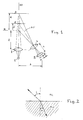
- Figure 1 which schematically represents the principle of a distance measurement by known triangulation, we recognizes the light source 1 and the emission optics which projects the beam from the light source onto the object to be measured 3 and 3 'which is at a distance d, respectively from a reference surface.
- the light diffusely reflected by the object to be measured is collected in a reception lens or a reception optic 4 and projected onto a position detector 5 located at a distance C from said receiving lens or optic 4.
- the distance b from the reference R of the position detector depends on the distance to be measured d.
- the basic idea of the present invention is to compress or amplify non-linearly the variation angle of light in reception optics.
- the realization of this inventive idea provides a compact detector with a large measuring range while reconciling the reception optics and the transmission optics.
- ⁇ r means the variation of the angle of refraction and ⁇ i the variation of the angle of incidence.
- Figure 3 shows very schematically the source of light 6, the emission optics 7 with the optical axis AO and the object to be measured 8 at a certain distance d from the source and object 9 shown in dotted lines at a distance reduced from which corresponds to a reduced dead zone.
- Figure 3 shows a variation between the incident beam i coming from object 8 located at the greatest distance d and the beam of incidence i 'coming from the object 9 located at the shorter distance of, i.e. a falling ⁇ i of 40 ° on the input face 10 of the prism 11, which produces a variation of the ⁇ r beam by 20 ° at the exit of the prism. it means that the measuring range of detector 12 is large and the small dead zone despite a small gap between the light source and position detector.
- Figure 3 also shows that the lens 13 which focuses the beam coming out of the prism on the position sensor can be integrated into the prism.
- Figures 4 and 5 show two exemplary embodiments a sensor, i.e. an optoelectronic assembly with a light source and a position detector.
- the Figure 4 is a schematic drawing showing on the left a transmitter system and on the right a receiver system, with the light source 6 in a housing 14 comprising means known (not shown) for holding and adjusting the source luminous and comprising bearings 15 blackened inside to generate as little reflection as possible.
- the optical system 7 projecting the light from light source 6 on the object to be measured, which is not shown.
- the optical axis AO is drawn in line batchwise. Towards the outside the case is closed by a optical window 16.
- the receiver system is integrated in the same box, which is closed to the outside by an optical window 17.
- the incident beam i 'from the object to be measured the most close together is about 40 ° to the optical axis AO and falls on the entry face 10 of the prism 11. This face input 10 is cut at around 45 ° to the axis optics AO '.
- the outgoing refracted beam then falls on a mirror 19 returning the beam to the position detector 12.
- the incident beam i coming from the position of the object at measure the farthest is refracted by the input face 10 of the prism and becomes the refracted beam r passing through also the lens 13 and falling on the mirror 19, from where it is returned to the position detector 12.
- the measuring device is located in a box and includes the position sensor and the circuits measurement and control known to those skilled in the art.
- the construction according to Figure 4 allows for a sensor reduced in size compared to a sensor according to the art prior.
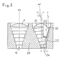
- the manufacturing example according to FIG. 5 allows further increase the detection distance and obtain a large measuring range with compact construction and reduced dimensions.
- the transmitting system and the system receiver are placed side by side in the same box 20.
- the transmitter system includes a source light 6 and a focusing lens 7 projecting the light on the object to be measured not shown.
- the system of reception consists of the association of a prism with focusing lens, as described in the example previous, and a lens or lens portion focusing the reflected light on the same detector position.
- the lens 21 When the reflected light falls at an angle included between -6 ° and 0 ° relative to the optical axis, the lens 21 focuses these beams on the position detector 24 between points -6 and 0.
- the beams i and i 'incidents are refracted by the input face 23 of the prism 22 and then focused by lens 25 on the position detector 24 located at right angles to relative to the optical axis.
- the refracted rays r and r ' are focused on the detector between the point O located exactly in the optical axis of the system and point 30 towards the end of the detector.
- the nonlinear angular compression produced by the prism lowers the angular sensitivity of the measurement when the distance to be measured decreases.
- the amount of light collected by the prism also decreases when the distance from measure decreases because more is then reflected outward from the entrance face of the prism. This is also a favorable parameter which tends to avoid the saturation of the measuring device.
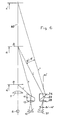
- the diagram of FIG. 6 includes that of FIG. 3 and in plus the arrangement for beam expansion.
- the prism 26 is located in such a way that the face inclined by relative to the optical axis AO '', which is parallel to the axis AO optics of the receiving optics, is the output face 29.
- the outlet face 29 can form an angle of about 40 ° with the optical axis AO ''.
- Figure 6 shows a variation between the incident beam i coming from object 8 located at the mean distance d and the incident beam i '' coming from the object located at the greatest distance from 'with an ⁇ i' of 8 ° falling on the prism 26 to produce a variation of the beam ⁇ r 'of 16 ° on the detector 27, at the outlet of the prism.
- Figure 6 allows make detectors measuring at long distance with a large measuring range, by combining an expanding optic angular or classic optics for long distance and angular compression optics for the area close.
- the manufacturing example described in Figure 7 shows the realization of a sensor combining the advantages of angular compression by prism 11 for measurements close together and angular expansion through the prism 26 for distant measurements.
- the transmitter system and receiver systems with two prisms are integrated side by side in the same box 31 and the construction is made very compact by using the same mirror spherical 30 to replace lens 13 or 25 and the lens 28, focusing the incident beams on the position sensors 12 or 24 for near measurements and 27 for distant measurements. It is possible to replace the only spherical mirror by two spherical mirrors, one for each prism. It is conceivable to provide only one detector instead of two detectors 12 or 24 and 27.
Description
La présente invention porte sur un dispositif de mesure de distances ou d'un angle d'incidence d'un faisceau lumineux selon le préambule de la revendication 1.The present invention relates to a device for measuring distances or angle of incidence of a light beam according to the preamble of claim 1.
En général, les mesures d'angle d'incidence ou de distance par des systèmes optoélectroniques sont basées sur le principe de triangulation décrit dans la figure 1. Pour l'obtention d'une bonne précision, il est nécessaire, avec cette méthode, d'avoir une base importante, ce qui constitue un premier inconvénient, auquel s'ajoute un second inconvénient, à savoir la forte limitation de la plage de mesure entraínant une zone morte Z importante. Ces inconvénients sont particulièrement gênants dans le cas d'un capteur. Celui-ci doit contenir la source de lumière et le récepteur dans un même boítier, dont l'encombrement doit être le plus restreint possible.In general, angle of attack or distance measurements by optoelectronic systems are based on the triangulation principle described in figure 1. For obtaining good accuracy, it is necessary, with this method, to have an important base, which constitutes a first drawback, to which is added a second disadvantage, namely the severe limitation of the range of measurement resulting in a large dead zone Z. These disadvantages are particularly troublesome in the case of a sensor. This must contain the light source and the receiver in the same box, whose size must be as small as possible.
Le brevet US-A-4 872 747 décrit l'utilisation de prismes pour obtenir un agrandissement anamorphique, comprenant un prisme pour contrôler la grandeur de l'image produite.US-A-4,872,747 describes the use of prisms to obtain an anamorphic enlargement, including a prism to control the size of the image produced.
EP-A-458 752 du même déposant décrit un procédé de mesure d'un angle d'incidence comprenant une lame biréfringente d'épaisseur variable en forme de prisme pour faire apparaítre, en lumière polarisée uniquement, une succession de franges d'interférence dont la position est déterminée par l'angle du faisceau et l'épaisseur de la lame.EP-A-458 752 by the same applicant describes a measurement method an angle of incidence comprising a birefringent blade of variable thickness in the form of a prism to make appear, in polarized light only, a succession interference fringes whose position is determined by the beam angle and the thickness of the blade.
Partant de cet état de la technique, l'invention a pour but la réalisation d'un dispositif de mesure de distances ou d'un angle d'incidence d'un faisceau lumineux, ayant une base restreinte, c'est-à-dire un encombrement réduit par rapport aux dispositifs connus et une plage de mesure plus importante.Starting from this state of the art, the invention aims the creation of a distance measuring device or of an angle of incidence of a light beam, having a restricted base, i.e. a reduced footprint by compared to known devices and a longer measuring range important.
Ce but est atteint grâce aux moyens définis dans l'un ou
l'autre des revendications indépendantes 1 et 2.This goal is achieved by the means defined in one or
the other of
L'invention sera expliquée en détail en se référant aux dessins ci-annexés, présentant à titre d'exemple des formes d'exécution de l'objet de l'invention.
- La figure 1
- montre schématiquement le principe de mesure de triangulation,
- la figure 2
- décrit la loi de Snell-Descartes,
- la figure 3
- montre le principe de mesure selon l'invention,
- la figure 4
- montre une première forme d'exécution d'un dispositif selon l'invention,
- la figure 5
- montre une deuxième forme d'exécution de l'invention,
- la figure 6
- montre un principe de mesure plus ample par rapport à celui de la figure 3, et
- la figure 7
- montre une autre forme d'exécution d'un dispositif selon l'invention.
- Figure 1
- schematically shows the principle of triangulation measurement,
- figure 2
- describes the Snell-Descartes law,
- figure 3
- shows the measuring principle according to the invention,
- figure 4
- shows a first embodiment of a device according to the invention,
- figure 5
- shows a second embodiment of the invention,
- figure 6
- shows a larger measurement principle compared to that of FIG. 3, and
- figure 7
- shows another embodiment of a device according to the invention.
Dans la figure 1, qui représente schématiquement le principe d'une mesure de distance par triangulation connu, l'on reconnaít la source lumineuse 1 et l'optique d'émission qui projette le faisceau émanant de la source lumineuse sur l'objet à mesurer 3 et 3' qui se trouve à une distance d, respectivement d' d'une surface de référence. La lumière réfléchie diffusément par l'objet à mesurer est collectée dans une lentille de réception ou une optique de réception 4 et projetée sur un détecteur de position 5 se trouvant à une distance C de ladite lentille ou optique de réception 4. Dans cet arrangement schématique la distance b de la référence R du détecteur de position est fonction de la distance à mesurer d.In Figure 1, which schematically represents the principle of a distance measurement by known triangulation, we recognizes the light source 1 and the emission optics which projects the beam from the light source onto the object to be measured 3 and 3 'which is at a distance d, respectively from a reference surface. The light diffusely reflected by the object to be measured is collected in a reception lens or a reception optic 4 and projected onto a position detector 5 located at a distance C from said receiving lens or optic 4. In this schematic arrangement the distance b from the reference R of the position detector depends on the distance to be measured d.
Pour obtenir une bonne précision, il est nécessaire d'avoir une base A importante entre l'axe optique AO de l'optique d'émission et l'axe optique AO' de l'optique de réception. De plus, comme cela ressort nettement de la figure 1, la plage de mesure est alors limitée par l'arrangement optique et la dimension du détecteur de position. On constate également la zone morte Z importante.To obtain good accuracy, it is necessary to have a significant base A between the optical axis AO of the optics emission and the optical axis AO 'of the reception optics. In addition, as is clear from Figure 1, the measuring range is then limited by the optical arrangement and the size of the position detector. We aknowledge also the important dead zone Z.
L'idée fondamentale de la présente invention consiste à comprimer ou amplifier non linéairement la variation angulaire de la lumière dans l'optique de réception. La réalisation de cette idée inventive permet de disposer d'un détecteur compact ayant une grande plage de mesure tout en rapprochant l'optique de réception et l'optique d'émission.The basic idea of the present invention is to compress or amplify non-linearly the variation angle of light in reception optics. The realization of this inventive idea provides a compact detector with a large measuring range while reconciling the reception optics and the transmission optics.
La propagation de la lumière dépend de l'indice de
réfraction du milieu qu'elle traverse, ce qui peut être
exprimé par la loi de Snell-Descartes (voir figure 2)
Si l'on considère la propagation du rayon lumineux qui passe d'un milieu plus réfringent à un milieu moins réfringent, on constate alors une expansion des variations angulaires, valable jusqu'à la réflexion totale selon la loi de Snell-Descartes. If we consider the propagation of the passing light ray from a more refractive medium to a less refractive medium, we then notes an expansion of the angular variations, valid until total reflection according to Snell-Descartes law.
Pour ne pas détruire l'effet de compression ou d'amplification, il faut veiller à ce que les faces d'entrée et de sortie ne soient pas parallèles. Ceci est habituellement réalisé en utilisant un prisme, mais il est aussi possible de recourir à un matériel optique dont l'indice de réfraction varie sur le chemin du faisceau lumineux. On bénéficiera ainsi d'une compression ou d'une amplification des variations angulaires même avec une lame dont les faces d'entrée et de sortie sont parallèles.In order not to destroy the compression effect or amplification, it must be ensured that the input faces and outlet are not parallel. this is usually achieved using a prism but it is also possible to use optical equipment including the refractive index varies along the beam path luminous. This will benefit from compression or amplification of angular variations even with a blade whose input and output faces are parallel.
On se réfère maintenant au cas d'un capteur (voir figure 3),
qui est une partie d'un dispositif de mesure comprenant en
outre des circuits électriques et électroniques et d'autres
composants. Si l'on désire faire des mesures à l'aide d'un
faisceau lumineux dont l'angle d'incidence, c'est-à-dire
l'angle de la lumière réfléchie, varie de Δi = 40°, on peut,
selon l'invention comprimer cette variation à environ 20° à
l'aide d'un prisme approprié. On aura ainsi augmenté
considérablement la plage de mesure du capteur. La
détermination des angles formés par les faces du prisme 11
produit une compression angulaire optimale sur la face
d'entrée dudit prisme et évite que la compression soit trop
affaiblie sur la face de sortie. Le faisceau sortant est
ensuite focalisé sur le détecteur de position par une
lentille qui pourra aussi être intégrée à la face de sortie
du prisme. La figure 3 montre très schématiquement la source
de lumière 6, l'optique d'émission 7 avec l'axe optique AO
et l'objet à mesurer 8 à une certaine distance d de la
source et l'objet 9 représenté en pointillé à une distance
réduite d' qui correspond à une zone morte réduite.We now refer to the case of a sensor (see Figure 3),
which is part of a measuring device comprising in
in addition to electrical and electronic circuits and others
components. If you wish to take measurements using a
light beam whose angle of incidence, i.e.
the angle of the reflected light varies from Δi = 40 °, we can,
according to the invention compress this variation to around 20 ° at
using an appropriate prism. We will have increased
considerably the measuring range of the sensor. The
determination of the angles formed by the faces of the
La figure 3 montre une variation entre le faisceau incident
i venant de l'objet 8 situé à la plus grande distance d et
le faisceau d'incidence i' venant de l'objet 9 situé à la
distance plus courte d', c'est-à-dire un Δi de 40° tombant
sur la face d'entrée 10 du prisme 11, qui produit une
variation du faisceau Δr de 20° à la sortie du prisme. Cela
veut dire que la plage de mesure du détecteur 12 est grande
et la zone morte petite malgré un faible écart entre la
source lumineuse et le détecteur de position. La figure 3
montre aussi que la lentille 13 qui focalise le faisceau
sortant du prisme sur le détecteur de position peut être
intégrée au prisme.Figure 3 shows a variation between the incident beam
i coming from
Les figures 4 et 5 montrent deux exemples de réalisation
d'un capteur, c'est-à-dire d'un ensemble optoélectronique
avec une source lumineuse et un détecteur de position. La
figure 4 est un dessin schématique montrant à gauche un
système émetteur et à droite un système récepteur, avec la
source lumineuse 6 dans un boítier 14 comprenant des moyens
connus (non-représentés) pour tenir et ajuster la source
lumineuse et comprenant des paliers 15 noircis à l'intérieur
pour générer le moins de réflexion possible. Vers la sortie
du boítier l'on reconnaít le système optique 7 projetant la
lumière de la source lumineuse 6 sur l'objet à mesurer, qui
n'est pas représenté. L'axe optique AO est dessiné en trait
discontinu. Vers l'extérieur le boítier est fermé par une
fenêtre optique 16.Figures 4 and 5 show two exemplary embodiments
a sensor, i.e. an optoelectronic assembly
with a light source and a position detector. The
Figure 4 is a schematic drawing showing on the left a
transmitter system and on the right a receiver system, with the
Le système récepteur est intégré dans le même boítier, qui
est fermé vers l'extérieur par une fenêtre optique 17. Le
faisceau incident i' provenant de l'objet à mesurer le plus
rapproché est environ à 40° par rapport à l'axe optique AO
et tombe sur la face d'entrée 10 du prisme 11. Cette face
d'entrée 10 est taillée à environ 45° par rapport à l'axe
optique AO'. Le faisceau réfracté r' du faisceau incident i'
traverse ensuite la lentille 13 intégrée à la face de sortie
du prisme et ayant par exemple une distance focale f = 6. Le
faisceau réfracté sortant tombe ensuite sur un miroir 19
renvoyant le faisceau sur le détecteur de position 12. Le
faisceau incident i venant de la position de l'objet à
mesurer la plus éloignée est réfracté par la face d'entrée
10 du prisme et devient le faisceau réfracté r traversant
aussi la lentille 13 et tombant sur le miroir 19, d'où il
est renvoyé sur le détecteur de position 12.The receiver system is integrated in the same box, which
is closed to the outside by an
Le dispositif de mesure se trouve dans un boítier et comprend le détecteur de position ainsi que les circuits de mesure et de commande connus de l'homme du métier. La construction selon la figure 4 permet de réaliser un capteur à dimension réduite par rapport à un capteur selon l'art antérieur.The measuring device is located in a box and includes the position sensor and the circuits measurement and control known to those skilled in the art. The construction according to Figure 4 allows for a sensor reduced in size compared to a sensor according to the art prior.
L'exemple de fabrication selon la figure 5 permet
d'augmenter encore la distance de détection et d'obtenir une
grande plage de mesure avec une construction compacte et des
dimensions réduites. Le système émetteur et le système
récepteur se trouvent placés côte-à-côte dans un même
boítier 20. Le système émetteur comprend une source
lumineuse 6 et une lentille de focalisation 7 projetant la
lumière sur l'objet à mesurer non représenté. Le système de
réception est constitué par l'association d'un prisme avec
lentille de focalisation, comme décrit dans l'exemple
précédent, et d'une lentille ou portion de lentille
focalisant la lumière réfléchie sur un même détecteur de
position.The manufacturing example according to FIG. 5 allows
further increase the detection distance and obtain a
large measuring range with compact construction and
reduced dimensions. The transmitting system and the system
receiver are placed side by side in the
Lorsque la lumière réfléchie tombe sous un angle compris
entre -6° et 0° par rapport à l'axe optique, la lentille 21
focalise ces faisceaux sur le détecteur de position 24 entre
les points -6 et 0.When the reflected light falls at an angle included
between -6 ° and 0 ° relative to the optical axis, the
Si l'angle d'incidence varie entre 0° et 30°, les faisceaux
i et i' incidents sont réfractés par la face 23 d'entrée du
prisme 22 et ensuite focalisés par la lentille 25 sur le
détecteur de position 24 se trouvant à angle droit par
rapport à l'axe optique. Les rayons réfractés r et r' sont
focalisés sur le détecteur entre le point O se trouvant
exactement dans l'axe optique du système et le point 30 vers
l'extrémité du détecteur.If the angle of incidence varies between 0 ° and 30 °, the beams
i and i 'incidents are refracted by the
La compression angulaire non linéaire produite par le prisme abaisse la sensibilité angulaire de la mesure lorsque la distance à mesurer diminue. La quantité de lumière collectée par le prisme diminue également lorsque la distance de mesure diminue car une plus grande partie est alors réfléchie vers l'extérieur par la face d'entrée du prisme. Ceci est également un paramètre favorable qui tend à éviter la saturation du dispositif de mesure.The nonlinear angular compression produced by the prism lowers the angular sensitivity of the measurement when the distance to be measured decreases. The amount of light collected by the prism also decreases when the distance from measure decreases because more is then reflected outward from the entrance face of the prism. This is also a favorable parameter which tends to avoid the saturation of the measuring device.
Avec l'arrangement optique décrit par la figure 6, on
cherche à augmenter encore la distance de détection en
utilisant le prisme 26 pour effectuer non pas une
compression mais une expansion angulaire de façon à
augmenter la sensibilité de mesure sur le détecteur de
position 27. Pour la mesure dans le domaine proche, on
utilisera l'information du détecteur de position 12 qui
donnera une mesure comprimée de la variation angulaire du
faisceau incident i' à i. La mesure dans un domaine éloigné
sera effectuée par le détecteur de position 27 qui, au
travers du prisme 26 et de la lentille 28, sera sensible à
une valeur expansée de la variation angulaire Δi' = i à i''.With the optical arrangement described in Figure 6, we
seeks to further increase the detection distance by
using
Le schéma de la figure 6 comprend celui de la figure 3 et en
plus l'arrangement pour l'expansion du faisceau. Le prisme
26 est situé de telle manière que la face inclinée par
rapport à l'axe optique AO'', qui est parallèle à l'axe
optique AO de l'optique de réception, est la face de sortie
29. La face de sortie 29 peut former un angle d'environ 40°
avec l'axe optique AO''. La figure 6 montre une variation
entre le faisceau incident i venant de l'objet 8 situé à la
distance moyenne d et le faisceau d'incidence i'' venant de
l'objet situé à la plus grande distance d'' avec un Δi' de
8° tombant sur le prisme 26 pour produire une variation du
faisceau Δr' de 16° sur le détecteur 27, à la sortie du
prisme.The diagram of FIG. 6 includes that of FIG. 3 and in
plus the arrangement for beam expansion. The
Selon les besoins, l'arrangement de la figure 6 permet de réaliser des détecteurs mesurant à grande distance avec une grande plage de mesure, en combinant une optique à expansion angulaire ou une optique classique pour la grande distance et une optique à compression angulaire pour la zone rapprochée.As required, the arrangement of Figure 6 allows make detectors measuring at long distance with a large measuring range, by combining an expanding optic angular or classic optics for long distance and angular compression optics for the area close.
L'exemple de fabrication décrit par la figure 7 montre la
réalisation d'un capteur réunissant les avantages de la
compression angulaire par le prisme 11 pour les mesures
rapprochées et de l'expansion angulaire par le prisme 26
pour les mesures éloignées. Le système émetteur et les
systèmes récepteurs avec les deux prismes sont intégrés
côte-à-côte dans un même boitier 31 et la construction est
rendue très compacte par l'utilisation d'un même miroir
sphérique 30 pour remplacer la lentille 13 ou 25 et la
lentille 28, focalisant les faisceaux incidents sur les
détecteurs de position 12 ou 24 pour les mesures proches et
27 pour les mesures éloignées. Il est possible de remplacer
le seul miroir sphérique par deux miroirs sphérique, un pour
chaque prisme. Il est concevable de prévoir un seul
détecteur au lieu des deux détecteurs 12 ou 24 et 27.The manufacturing example described in Figure 7 shows the
realization of a sensor combining the advantages of
angular compression by
Si dans les figures 6 et 7 les deux processus, compression et expansion des variations angulaires, ont été décrits et démontrés ensemble, il est bien possible de n'utiliser qu'un seul des deux processus.If in Figures 6 and 7 the two processes, compression and expansion of angular variations, have been described and demonstrated together, it is quite possible to use only one only one of the two processes.
Claims (10)
- Device for the measurement of distances or of the angle of incidence of a light beam, comprising an optical emitting system (7) for projecting the light beam onto the object to be measured, and an optical receiving system (11, 13; 21, 22, 25) for projecting the reflected light onto a position detector, characterised in that the optical receiving system (11, 13; 21, 22, 25; 30) comprises a prism (11, 22) which refracts the light beam with a compression of the angular variations thereof, thus allowing to reduce the area of the position detector (12, 24) required in order to measure a corresponding measuring range.
- Device for the measurement of distances or of the angle of incidence of a light beam, comprising an optical emitting system (7) for projecting the light beam onto the object to be measured, and an optical receiving system (26, 28, 29; 30) for projecting the reflected light onto a position detector, characterised in that the optical receiving system comprises a first element in the form a prism (26) which refracts the light beam with an expansion of the angular variations thereof, thus allowing to increase the sensitivity of the position detector (27) for small angular variations.
- Device according to claim 1, characterised in that the entrance surface (10, 23) of the prism (11, 22) forms an angle of approximately 45° with the optical axis (AO') of the optical receiving system.
- Device according to claim 2, characterised in that the exit surface (29) of the prism (26) forms an angle of approximately 40° with the optical axis (AO) of the optical receiving system.
- Device according to any one of claims 1 to 4, characterised in that the exit surface of the prism comprises optical elements (13, 25; 28; 30) for projecting the refracted beam onto the position detector (12, 24, 27).
- Device according to claim 5, characterised in that the optical elements at the exit surface of the first prism (11) and at the exit surface (29) of the second prism (26) are comprised of a single spherical mirror (30) or of two spherical mirrors which focus the diffracted beams onto the position detector(s) (12, 24, 27).
- Device according to any one of claims 1, 3, 5, or 6, characterised in that the optical receiving system, comprising the prism (11), is separated from the optical emitting system and comprises a mirror (19) which is arranged under the exit surface of the prism with the optical elements (13) in order to project the refracted beam onto the position detector (12) which is arranged in parallel to the optical axis (AO'), the optical emitting and receiving systems forming a sensor which is arranged in a housing (14).
- Device according to any one of claims 1, 3, 5, or 6, characterised in that the optical receiving system (21; 22, 25) comprises a combination of the prism (22) with a focusing lens (25) and of a focusing lens or lens portion (21), each of these elements being designed for receiving the reflected light and projecting the reflected light onto the position detector (24), depending on the angle formed between the beam and the optical axis (AO') of the optical receiving system.
- Device according to claim 8, characterised in that the position detector (24) is disposed at 90° with respect to the optical axis (AO') of the optical receiving system.
- Device according to any one of claims 1 to 9, characterised by an assembly which combines the optical emitting system (7) and the optical receiving system (11, 13, 21, 22, 25, 30) which refracts the light beam with a compression, and the optical receiving system (26, 28, 29, 30) which refracts the light beam with an expansion of the angular variations, as well as the position detector(s) (12, 24; 27) in one housing (31).
Priority Applications (4)
| Application Number | Priority Date | Filing Date | Title |
|---|---|---|---|
| EP98811242A EP0942293B1 (en) | 1998-02-10 | 1998-12-17 | System for measuring range or angle of incidence of a light beam |
| US09/240,698 US6133988A (en) | 1998-02-10 | 1999-02-02 | Device for the measurement of distances or of the angle of incidence of a light beam |
| JP03114599A JP4370012B2 (en) | 1998-02-10 | 1999-02-09 | Distance or ray incident angle measuring device |
| CA002261332A CA2261332A1 (en) | 1998-02-10 | 1999-02-09 | Device for the measurement of distances or of the angle of incidence of light beam |
Applications Claiming Priority (3)
| Application Number | Priority Date | Filing Date | Title |
|---|---|---|---|
| EP98810102 | 1998-02-10 | ||
| EP98810102 | 1998-02-10 | ||
| EP98811242A EP0942293B1 (en) | 1998-02-10 | 1998-12-17 | System for measuring range or angle of incidence of a light beam |
Publications (3)
| Publication Number | Publication Date |
|---|---|
| EP0942293A2 EP0942293A2 (en) | 1999-09-15 |
| EP0942293A3 EP0942293A3 (en) | 2000-01-19 |
| EP0942293B1 true EP0942293B1 (en) | 2002-05-29 |
Family
ID=26151866
Family Applications (1)
| Application Number | Title | Priority Date | Filing Date |
|---|---|---|---|
| EP98811242A Expired - Lifetime EP0942293B1 (en) | 1998-02-10 | 1998-12-17 | System for measuring range or angle of incidence of a light beam |
Country Status (4)
| Country | Link |
|---|---|
| US (1) | US6133988A (en) |
| EP (1) | EP0942293B1 (en) |
| JP (1) | JP4370012B2 (en) |
| CA (1) | CA2261332A1 (en) |
Families Citing this family (19)
| Publication number | Priority date | Publication date | Assignee | Title |
|---|---|---|---|---|
| SE522366C2 (en) * | 1999-02-26 | 2004-02-03 | Latronix Ab | RANGE-FINDER |
| DE10011046A1 (en) * | 2000-03-07 | 2001-10-04 | Omron Electronics Mfg Of Germa | Detecting object spacing by triangulation sensors, using phototransmitter and reflected light detector |
| US6369879B1 (en) * | 2000-10-24 | 2002-04-09 | The Regents Of The University Of California | Method and apparatus for determining the coordinates of an object |
| JP2003035534A (en) * | 2001-07-25 | 2003-02-07 | Sumitomo Osaka Cement Co Ltd | Distance sensor and distance sensor array |
| DE10214280A1 (en) * | 2002-03-28 | 2003-10-16 | Bosch Gmbh Robert | Device for optical distance measurement |
| DE10220037C5 (en) * | 2002-05-04 | 2011-02-24 | Sick Ag | Device for detecting objects |
| DE10305861A1 (en) * | 2003-02-13 | 2004-08-26 | Adam Opel Ag | Motor vehicle device for spatial measurement of a scene inside or outside the vehicle, combines a LIDAR system with an image sensor system to obtain optimum 3D spatial image data |
| DE10331074A1 (en) * | 2003-07-09 | 2005-02-03 | Conti Temic Microelectronic Gmbh | Sensor arrangement for distance and / or speed measurement |
| DE102005045280B3 (en) * | 2005-09-22 | 2006-12-28 | Leuze Electronic Gmbh & Co Kg | Distance sensor has receiver with light sensitive surface enclosed by frame with normal vector inclined to optical axis by defined angle so received light beams incident on frame are deflected to side, no longer pass into monitored region |
| DE102006013292A1 (en) * | 2006-03-23 | 2007-09-27 | Robert Bosch Gmbh | Device for optical distance measurement |
| US20100133424A1 (en) * | 2007-05-26 | 2010-06-03 | Norman Matheson Lindsay | Electro-optical sensors |
| DE102009047662A1 (en) | 2009-12-08 | 2011-06-09 | Endress + Hauser Gmbh + Co. Kg | Device for measuring fill level of filling goods in container, has inlet and outlet surfaces whose radii of curvatures are determined such that radiations reflected at meniscus by object produce angle reinforced refraction and collimation |
| DE102010040051A1 (en) * | 2010-08-31 | 2012-03-01 | Balluff Gmbh | Photointerrupter |
| CN103477242B (en) * | 2011-04-15 | 2015-08-12 | 欧司朗光电半导体有限公司 | Photoelectron device |
| DE102014114314A1 (en) * | 2014-10-01 | 2016-04-07 | Sick Ag | Optoelectronic sensor |
| DE102014116254A1 (en) * | 2014-11-07 | 2016-05-12 | Sick Ag | sensor |
| TW201804131A (en) * | 2016-07-20 | 2018-02-01 | 陳進益 | Portable distance measuring device with integrated dual lens and curved optical disc capable of increasing angle resolution by the cooperation of an angle reading module of the curved optical disc and the image-based distance measurement of the dual lenses |
| KR20190051409A (en) * | 2017-11-07 | 2019-05-15 | 주식회사 엘지화학 | A sheet and an optical fingerprint scanner |
| CN111522135B (en) * | 2020-03-20 | 2022-02-11 | 北京国泰蓝盾科技有限公司 | Large-aperture catadioptric lens suitable for triangulation |
Family Cites Families (4)
| Publication number | Priority date | Publication date | Assignee | Title |
|---|---|---|---|---|
| JPS63235909A (en) * | 1987-03-24 | 1988-09-30 | Fuji Photo Optical Co Ltd | Active type autofocus mechanism |
| US4872747A (en) * | 1987-04-15 | 1989-10-10 | Cyberoptics Corporation | Use of prisms to obtain anamorphic magnification |
| JPS6465460A (en) * | 1987-09-07 | 1989-03-10 | Hitachi Ltd | Space filter type speed measuring instrument |
| CH683381A5 (en) * | 1990-05-23 | 1994-02-28 | Charles Rheme | A method of measuring an angle of incidence of a light beam, measurement device for the implementation of the method and use of the device for measuring distances. |
-
1998
- 1998-12-17 EP EP98811242A patent/EP0942293B1/en not_active Expired - Lifetime
-
1999
- 1999-02-02 US US09/240,698 patent/US6133988A/en not_active Expired - Lifetime
- 1999-02-09 JP JP03114599A patent/JP4370012B2/en not_active Expired - Lifetime
- 1999-02-09 CA CA002261332A patent/CA2261332A1/en not_active Abandoned
Also Published As
| Publication number | Publication date |
|---|---|
| CA2261332A1 (en) | 1999-08-10 |
| US6133988A (en) | 2000-10-17 |
| EP0942293A3 (en) | 2000-01-19 |
| JP2000065566A (en) | 2000-03-03 |
| EP0942293A2 (en) | 1999-09-15 |
| JP4370012B2 (en) | 2009-11-25 |
Similar Documents
| Publication | Publication Date | Title |
|---|---|---|
| EP0942293B1 (en) | System for measuring range or angle of incidence of a light beam | |
| WO2002095475A1 (en) | Method and device for measurement by extended chromatism confocal imaging | |
| FR2490433A1 (en) | TRANSMISSION SYSTEM USING OPTICAL FIBER | |
| CA2045244A1 (en) | Meteorological parameter measuring device | |
| FR2495315A1 (en) | OPTICAL FIBER MEASURING DEVICE | |
| EP0846274B1 (en) | Optical velocimetry sensor | |
| CA2220940C (en) | Device for determining phase faults in electromagnetic waves | |
| FR2498318A1 (en) | COMBINED SPEED AND DIMENSION MEASURING APPARATUS | |
| FR2848664A1 (en) | Position and reflectivity meter for use in photometry and metrology has a light source with at least two different wavelengths that are processed separately by a measurement system | |
| WO1993020416A1 (en) | Phase detection deflectometer-type optical device having a large measuring range | |
| FR3084158A1 (en) | METHOD AND DEVICE FOR CHARACTERIZING OPTICAL FILTERS | |
| CA2405956C (en) | Device for acquiring a three-dimensional shape by optoelectronic process | |
| FR2761162A1 (en) | Optical Doppler effect speed detection system | |
| EP0448415B1 (en) | Device to detect a physical entity at a distance, functioning by means of reflection | |
| WO2000009978A1 (en) | Apparatus for measuring a light beam wavelength | |
| EP0287448A1 (en) | Method and apparatus for the measurement by reflection of the optical transmission coefficient of a vitreous tinted wall | |
| FR2649493A1 (en) | OPTICAL SENSOR FOR THE IDENTIFICATION AND DIRECTIONAL DETECTION OF OPTICAL RADIATION | |
| FR2567651A1 (en) | Equipment for measuring the speed of a projectile by interferometry using a laser beam propagated by a single optical waveguide | |
| FR2710146A1 (en) | Optical device for measuring transverse deviation. | |
| FR2728971A1 (en) | MULTIFUNCTION DISCREET TELEMETER | |
| FR3071069B1 (en) | MONOSTATIC LASER TELEMETRY DEVICE | |
| EP0911645A1 (en) | Optical apparatus with polarisation modulation for measuring distance to, or velocity of, an object | |
| FR2844603A3 (en) | Laser radar fiber optic coupling system having laser source/lens forming image with light through mirror hole and coupled fibers/telescope section detector/lens | |
| FR3064058A1 (en) | OPTICAL SYSTEM AND MINIATURE SPECTROMETER EQUIPPED WITH SUCH A SYSTEM AND METHOD OF ANALYZING OBJECTS USING SUCH AN OPTICAL SYSTEM | |
| FR2653254A1 (en) | DEVICE FOR PERFORMING THE MEASUREMENT OF A PHYSICAL QUANTITY AND THE REMOTE TRANSMISSION OF THE LARGED VALUE OF THIS QUANTITY. |
Legal Events
| Date | Code | Title | Description |
|---|---|---|---|
| PUAI | Public reference made under article 153(3) epc to a published international application that has entered the european phase |
Free format text: ORIGINAL CODE: 0009012 |
|
| AK | Designated contracting states |
Kind code of ref document: A2 Designated state(s): AT BE CH DE ES FR GB IT LI NL SE |
|
| AX | Request for extension of the european patent |
Free format text: AL;LT;LV;MK;RO;SI |
|
| PUAL | Search report despatched |
Free format text: ORIGINAL CODE: 0009013 |
|
| RIC1 | Information provided on ipc code assigned before grant |
Free format text: 7G 01S 17/46 A, 7G 01S 7/481 B |
|
| AK | Designated contracting states |
Kind code of ref document: A3 Designated state(s): AT BE CH CY DE DK ES FI FR GB GR IE IT LI LU MC NL PT SE |
|
| AX | Request for extension of the european patent |
Free format text: AL;LT;LV;MK;RO;SI |
|
| 17P | Request for examination filed |
Effective date: 20000219 |
|
| RIN1 | Information on inventor provided before grant (corrected) |
Inventor name: HEIMLICHER, PETER Inventor name: RHEME, CHARLES |
|
| K1C3 | Correction of patent application (complete document) published |
Effective date: 20000119 |
|
| AKX | Designation fees paid |
Free format text: AT BE CH DE ES FR GB IT LI NL SE |
|
| 17Q | First examination report despatched |
Effective date: 20000927 |
|
| GRAG | Despatch of communication of intention to grant |
Free format text: ORIGINAL CODE: EPIDOS AGRA |
|
| GRAG | Despatch of communication of intention to grant |
Free format text: ORIGINAL CODE: EPIDOS AGRA |
|
| GRAH | Despatch of communication of intention to grant a patent |
Free format text: ORIGINAL CODE: EPIDOS IGRA |
|
| GRAH | Despatch of communication of intention to grant a patent |
Free format text: ORIGINAL CODE: EPIDOS IGRA |
|
| GRAA | (expected) grant |
Free format text: ORIGINAL CODE: 0009210 |
|
| AK | Designated contracting states |
Kind code of ref document: B1 Designated state(s): AT BE CH DE ES FR GB IT LI NL SE |
|
| PG25 | Lapsed in a contracting state [announced via postgrant information from national office to epo] |
Ref country code: NL Free format text: LAPSE BECAUSE OF FAILURE TO SUBMIT A TRANSLATION OF THE DESCRIPTION OR TO PAY THE FEE WITHIN THE PRESCRIBED TIME-LIMIT Effective date: 20020529 Ref country code: AT Free format text: LAPSE BECAUSE OF FAILURE TO SUBMIT A TRANSLATION OF THE DESCRIPTION OR TO PAY THE FEE WITHIN THE PRESCRIBED TIME-LIMIT Effective date: 20020529 |
|
| REF | Corresponds to: |
Ref document number: 218210 Country of ref document: AT Date of ref document: 20020615 Kind code of ref document: T |
|
| REG | Reference to a national code |
Ref country code: GB Ref legal event code: FG4D Free format text: NOT ENGLISH |
|
| REG | Reference to a national code |
Ref country code: CH Ref legal event code: NV Representative=s name: AMMANN PATENTANWAELTE AG BERN Ref country code: CH Ref legal event code: EP |
|
| REF | Corresponds to: |
Ref document number: 69805598 Country of ref document: DE Date of ref document: 20020704 |
|
| GBT | Gb: translation of ep patent filed (gb section 77(6)(a)/1977) |
Effective date: 20020720 |
|
| PG25 | Lapsed in a contracting state [announced via postgrant information from national office to epo] |
Ref country code: SE Free format text: LAPSE BECAUSE OF FAILURE TO SUBMIT A TRANSLATION OF THE DESCRIPTION OR TO PAY THE FEE WITHIN THE PRESCRIBED TIME-LIMIT Effective date: 20020829 |
|
| NLV1 | Nl: lapsed or annulled due to failure to fulfill the requirements of art. 29p and 29m of the patents act | ||
| PG25 | Lapsed in a contracting state [announced via postgrant information from national office to epo] |
Ref country code: ES Free format text: LAPSE BECAUSE OF FAILURE TO SUBMIT A TRANSLATION OF THE DESCRIPTION OR TO PAY THE FEE WITHIN THE PRESCRIBED TIME-LIMIT Effective date: 20021128 |
|
| PG25 | Lapsed in a contracting state [announced via postgrant information from national office to epo] |
Ref country code: BE Free format text: LAPSE BECAUSE OF NON-PAYMENT OF DUE FEES Effective date: 20021231 |
|
| PLBE | No opposition filed within time limit |
Free format text: ORIGINAL CODE: 0009261 |
|
| STAA | Information on the status of an ep patent application or granted ep patent |
Free format text: STATUS: NO OPPOSITION FILED WITHIN TIME LIMIT |
|
| 26N | No opposition filed |
Effective date: 20030303 |
|
| BERE | Be: lapsed |
Owner name: S.A. *OPTOSYS Effective date: 20021231 |
|
| REG | Reference to a national code |
Ref country code: FR Ref legal event code: PLFP Year of fee payment: 18 |
|
| REG | Reference to a national code |
Ref country code: FR Ref legal event code: PLFP Year of fee payment: 19 |
|
| REG | Reference to a national code |
Ref country code: FR Ref legal event code: PLFP Year of fee payment: 20 |
|
| PGFP | Annual fee paid to national office [announced via postgrant information from national office to epo] |
Ref country code: DE Payment date: 20171211 Year of fee payment: 20 Ref country code: FR Payment date: 20171221 Year of fee payment: 20 |
|
| PGFP | Annual fee paid to national office [announced via postgrant information from national office to epo] |
Ref country code: CH Payment date: 20171221 Year of fee payment: 20 Ref country code: GB Payment date: 20171221 Year of fee payment: 20 |
|
| PGFP | Annual fee paid to national office [announced via postgrant information from national office to epo] |
Ref country code: IT Payment date: 20171221 Year of fee payment: 20 |
|
| REG | Reference to a national code |
Ref country code: DE Ref legal event code: R071 Ref document number: 69805598 Country of ref document: DE |
|
| REG | Reference to a national code |
Ref country code: CH Ref legal event code: PL |
|
| REG | Reference to a national code |
Ref country code: GB Ref legal event code: PE20 Expiry date: 20181216 |
|
| PG25 | Lapsed in a contracting state [announced via postgrant information from national office to epo] |
Ref country code: GB Free format text: LAPSE BECAUSE OF EXPIRATION OF PROTECTION Effective date: 20181216 |