EP0941886A2 - Device for motor vehicle gear shift arranged on the steering wheel - Google Patents
Device for motor vehicle gear shift arranged on the steering wheel Download PDFInfo
- Publication number
- EP0941886A2 EP0941886A2 EP99102517A EP99102517A EP0941886A2 EP 0941886 A2 EP0941886 A2 EP 0941886A2 EP 99102517 A EP99102517 A EP 99102517A EP 99102517 A EP99102517 A EP 99102517A EP 0941886 A2 EP0941886 A2 EP 0941886A2
- Authority
- EP
- European Patent Office
- Prior art keywords
- steering wheel
- driver
- switching
- switch device
- switch
- Prior art date
- Legal status (The legal status is an assumption and is not a legal conclusion. Google has not performed a legal analysis and makes no representation as to the accuracy of the status listed.)
- Granted
Links
Images


Classifications
-
- B—PERFORMING OPERATIONS; TRANSPORTING
- B60—VEHICLES IN GENERAL
- B60K—ARRANGEMENT OR MOUNTING OF PROPULSION UNITS OR OF TRANSMISSIONS IN VEHICLES; ARRANGEMENT OR MOUNTING OF PLURAL DIVERSE PRIME-MOVERS IN VEHICLES; AUXILIARY DRIVES FOR VEHICLES; INSTRUMENTATION OR DASHBOARDS FOR VEHICLES; ARRANGEMENTS IN CONNECTION WITH COOLING, AIR INTAKE, GAS EXHAUST OR FUEL SUPPLY OF PROPULSION UNITS IN VEHICLES
- B60K20/00—Arrangement or mounting of change-speed gearing control devices in vehicles
- B60K20/02—Arrangement or mounting of change-speed gearing control devices in vehicles of initiating means
- B60K20/06—Arrangement or mounting of change-speed gearing control devices in vehicles of initiating means mounted on steering column or the like
-
- F—MECHANICAL ENGINEERING; LIGHTING; HEATING; WEAPONS; BLASTING
- F16—ENGINEERING ELEMENTS AND UNITS; GENERAL MEASURES FOR PRODUCING AND MAINTAINING EFFECTIVE FUNCTIONING OF MACHINES OR INSTALLATIONS; THERMAL INSULATION IN GENERAL
- F16H—GEARING
- F16H59/00—Control inputs to control units of change-speed-, or reversing-gearings for conveying rotary motion
- F16H59/02—Selector apparatus
- F16H2059/0239—Up- and down-shift or range or mode selection by repeated movement
- F16H2059/0247—Up- and down-shift or range or mode selection by repeated movement with lever or paddle behind steering wheel
Definitions
- the invention relates to an actuating device rotating with a steering wheel for switching the gear stages of a vehicle transmission according to the generic term of the main claim.
- EP 0 519 528 B1 describes a transmission control module, the manually operated one Switch to shift up or down an automatic transmission on Steering wheel are attached.
- the described way of attachment to the steering wheel namely diametrically opposite each other on different sides of the steering wheel, with the same actuation direction for shifting up and down, has the Disadvantage that not only the control element has its place due to a steering movement changes, but also, especially with half a turn of the steering wheel Function of the controls with respect to the driver position changes. This can be too Carry out incorrect switching by the driver.
- a manual actuator rotating with a steering wheel for switching the gear stages of a vehicle transmission in particular of an auxiliary power transmission, consisting of at least one on Steering wheel attached switch device that enables the gears of the Shifting the vehicle transmission sequentially up and down, characterized in that that the switching direction for upshifting the gear stages of the switching direction for switching down the gear stages in essentially the opposite direction is and both switching directions essentially in the direction of a vehicle longitudinal plane run.
- a preferred embodiment of the invention provides that the switch device self-resetting toggle switch that can be moved in opposite directions, with the advantage that only one switch device for upshifting and one downshifting must be attached to the steering wheel with one connection each.
- Switch device consisting of two self-resetting switches. That has the advantage, that the switches for upshifting the gears are independent of the switches ergonomically for the driver to switch down the gear on the steering wheel can be placed cheaply.
- An advantageous embodiment of the invention provides that the switching direction for Upshifting the gear steps away from the driver and the shift direction is executed to downshift the gears to the driver or vice versa.
- Such a type of attachment of the switch devices to the steering wheel is taken into account ergonomically advantageous also the location of the fingers of the Driver on the steering wheel. For example, with the thumb in one direction without Change in hand position to be sequentially shifted up during that sequential switching back with another finger of this hand in the other Direction can take place, also without changing the position of the hand on the steering wheel. This is especially true when the switch device on the steering wheel is on or is attached near a steering wheel rim so that it is within easy reach of the fingers of the driver when the steering wheel is in a straight-ahead position holds.
- Such a switch device for upshifting and downshifting is used for each hand is provided, so avoiding incorrect switching even then given when shifting up with one hand, downshifting with the other hand and at the same time the steering wheel is turned. Even if the steering wheel is twisted so that one switch device takes the position of the other, which would take this when driving straight ahead are the switching directions for Upshifting and downshifting did not change in their function and the driver can the manual control without thinking in any position of the steering wheel use to shift the gears of the vehicle transmission.
- FIG. 1 shows the front of a steering wheel 1, consisting of a steering wheel hub 2, four steering wheel spokes 3 and a steering wheel rim 4.
- a switch device 5 for manual switching of the gear stages is not on the steering wheel hub 2 in the direction of the steering wheel rim 4 drawn vehicle transmission attached.
- the switch devices 5 rotate with the steering wheel 1 when the steering wheel moves. You are so close to the steering wheel rim 4 that they are within reach of the not shown fingers of the driver, not shown, when he holds the steering wheel 1 in a position for straight travel.
- the driver can use a thumb of his left or right hand, not shown on the steering wheel 1, by moving the left or right switch device 5 in a switching direction away from him.
- the embodiment of the actuating device for switching the gear stages of a vehicle transmission differs from that described in Figures 1 and 2 further in that the arrangement of the switch devices 5 on the steering wheel 1 is chosen differently and that overall four switch devices 5 are used.
- actuation of one of the switch devices 5 on the front of the steering wheel 1 in the switching direction away from the driver switches the vehicle transmission sequentially, while actuation of the switch devices 5 on the rear of the steering wheel 1, in the switching direction towards the driver, that Shifting the vehicle transmission sequentially. Therefore, the drawing symbol is on the switch devices 5 in FIG Minus "represented, while in Figure 4 the opposite switching direction for upshifting by the symbol 4 represents the rear of the steering wheel 1 and FIG. 3 the front.
- Switch devices 5 are used which can be moved as self-resetting rockers for shifting up and down in two opposite directions.
- the switch devices 5 are attached to the steering wheel rim 4 , at its transition to the steering wheel spokes 3.
- each switch device 5 from two self-resetting Pressure switches 6.7 There are a total of four switch devices 5 drawn, 3 on each steering wheel spoke.
- the sequential downshift can optionally with any of the Pressure switch 6 can be accomplished alone or with all pressure switches 6 in optional variety.
- One of the pressure switches 7 for shifting up the gear steps of the vehicle transmission is visible in Figure 6. They are on the back the steering wheel spokes 3 and are by a movement towards the driver operated.
- the switch devices 5 of this embodiment, as a pressure switch 6,7 are placed near the steering wheel rim 4 so that they are within easy reach the undrawn fingers of the driver when the steering wheel stops in a straight-ahead position.
Landscapes
- Engineering & Computer Science (AREA)
- Chemical & Material Sciences (AREA)
- Combustion & Propulsion (AREA)
- Transportation (AREA)
- Mechanical Engineering (AREA)
- Arrangement Or Mounting Of Control Devices For Change-Speed Gearing (AREA)
- Control Of Transmission Device (AREA)
Abstract
Description
Die Erfindung betrifft eine mit einem Lenkrad sich mitdrehende Betätigungseinrichtung zum Schalten der Gangstufen eines Fahrzeuggetriebes nach dem Oberbegriff des Hauptanspruchs.The invention relates to an actuating device rotating with a steering wheel for switching the gear stages of a vehicle transmission according to the generic term of the main claim.
Die EP 0 519 528 B1 beschreibt ein Getrieberegelungsmodul, dessen manuell bedienbare Schalter zum Hoch- oder Zurückschalten eines Automatikgetriebes am Lenkrad angebracht sind. Die beschriebene Anbringungsweise am Lenkrad, nämlich sich einander diametral gegenüberliegend an verschiedenen Seiten des Lenkrads, bei derselben Betätigungsrichtung zum Hoch- und zum Zurückschalten, hat den Nachteil, daß durch eine Lenkbewegung nicht nur das Bedienelement seinen Platz wechselt, sondern auch, insbesondere bei einer halben Lenkradumdrehung, die Funktion der Bedienelemente bezüglich der Fahrerposition wechselt. Dies kann zu Fehlschaltungen durch den Fahrer führen.EP 0 519 528 B1 describes a transmission control module, the manually operated one Switch to shift up or down an automatic transmission on Steering wheel are attached. The described way of attachment to the steering wheel, namely diametrically opposite each other on different sides of the steering wheel, with the same actuation direction for shifting up and down, has the Disadvantage that not only the control element has its place due to a steering movement changes, but also, especially with half a turn of the steering wheel Function of the controls with respect to the driver position changes. This can be too Carry out incorrect switching by the driver.
Deshalb ist es Aufgabe der Erfindung, eine mit einem Lenkrad sich mitdrehende manuelle Betätigungseinrichtung zum Schalten der Gangstufen eines Fahrzeuggetriebes bereitzustellen, bei der eine Fehlbedienung aufgrund des Ortswechsels der Bedienelemente beim Lenken ausgeschlossen ist. Therefore, it is an object of the invention to rotate with a steering wheel manual actuating device for switching the gear stages of a vehicle transmission to provide in the event of incorrect operation due to the change of location the controls when steering is excluded.
Die Aufgabe wird erfindungsgemäß mit den kennzeichnenden Merkmalen des Anspruchs 1 gelöst. Weitere Ausgestaltungen der Erfindung ergeben sich aus den Unteransprüchen.The object is achieved with the characterizing features of the claim 1 solved. Further refinements of the invention result from the Subclaims.
Nach der Erfindung ist eine mit einem Lenkrad sich mitdrehende manuelle Betätigungseinrichtung zum Schalten der Gangstufen eines Fahrzeuggetriebes, insbesondere eines hilfskraftgeschalteten Getriebes, bestehend aus mindestens einer am Lenkrad angebrachten Schaltereinrichtung, die es ermöglicht, die Gangstufen des Fahrzeuggetriebes sequentiell Hoch- und Zurückzuschalten, dadurch gekennzeichnet, daß die Schaltrichtung zum Hochschalten der Gangstufen der Schaltrichtung zum Zurückschalten der Gangstufen im wesentlichen entgegengesetzt gerichtet ist und beide Schaltrichtungen im wesentlichen in Richtung einer Fahrzeuglängsebene verlaufen.According to the invention is a manual actuator rotating with a steering wheel for switching the gear stages of a vehicle transmission, in particular of an auxiliary power transmission, consisting of at least one on Steering wheel attached switch device that enables the gears of the Shifting the vehicle transmission sequentially up and down, characterized in that that the switching direction for upshifting the gear stages of the switching direction for switching down the gear stages in essentially the opposite direction is and both switching directions essentially in the direction of a vehicle longitudinal plane run.
Das hat den Vorteil, daß selbst bei einer Anordnung von mehreren Bedienelementen am Lenkrad, die durch eine Lenkraddrehung einem Ortswechsel unterworfen sind und dabei ihre Position gegenseitig vertauschen können, sich ihre Funktion bezüglich der Schaltrichtung für Hoch- und Zurückschalten nicht ändert.This has the advantage that even with an arrangement of several controls on the steering wheel, which is subject to a change of location by turning the steering wheel are and can swap positions, theirs Function with regard to the switching direction for upshifts and downshifts does not change.
Eine bevorzugte Ausführung der Erfindung sieht vor, daß die Schaltereinrichtung ein in entgegengesetzte Richtungen bewegbarer, selbstrückstellender Kippschalter ist, mit dem Vorteil, daß für das Hoch- und Zurückschalten nur jeweils eine Schaltereinrichtung mit jeweils einem Anschluß am Lenkrad angebracht werden muß.A preferred embodiment of the invention provides that the switch device self-resetting toggle switch that can be moved in opposite directions, with the advantage that only one switch device for upshifting and one downshifting must be attached to the steering wheel with one connection each.
Bei einer weiteren bevorzugten Ausführung der Erfindung besteht jeweils eine Schaltereinrichtung aus zwei selbstrückstellenden Schaltern. Das hat den Vorteil, daß die Schalter zum Hochschalten der Gangstufen unabhängig von den Schaltern zum Zurückschalten der Gangstufen am Lenkrad für den Fahrer ergonomisch günstig plaziert werden können.In a further preferred embodiment of the invention there is one Switch device consisting of two self-resetting switches. That has the advantage, that the switches for upshifting the gears are independent of the switches ergonomically for the driver to switch down the gear on the steering wheel can be placed cheaply.
Eine vorteilhafte Ausführung der Erfindung sieht vor, daß die Schaltrichtung zum Hochschalten der Gangstufen vom Fahrer weggerichtet ist und die Schaltrichtung zum Zurückschalten der Gangstufen zum Fahrer hingerichtet ist oder umgekehrt. Eine solche Art der Anbringung der Schaltereinrichtungen am Lenkrad berücksichtigt ergonomisch vorteilhafterweise zusätzlich noch die Lage der Finger des Fahrers am Lenkrad. So kann zum Beispiel mit dem Daumen in einer Richtung ohne Veränderung der Lage der Hand sequentiell hochgeschaltet werden, während das sequentielle Zurückschalten mit einem anderen Finger dieser Hand in der anderen Richtung erfolgen kann, ebenfalls ohne die Lage der Hand am Lenkrad zu verändern. Dies vor allem dann, wenn die Schaltereinrichtung am Lenkrad an oder nahe einem Lenkradkranz so angebracht ist, daß sie sich in Reichweite der Finger des Fahrers befindet, wenn dieser das Lenkrad in einer Stellung für Geradeausfahrt hält. Wird dabei für jede Hand eine solche Schaltereinrichtung zum Hoch- und Zurückschalten vorgesehen, so ist ein Vermeiden von Fehlschaltungen selbst dann gegeben, wenn mit einer Hand hochgeschaltet wird, mit der anderen Hand zurückgeschaltet wird und gleichzeitig das Lenkrad verdreht wird. Selbst wenn das Lenkrad so verdreht ist, daß eine Schaltereinrichtung die Stellung der anderen einnimmt, die diese bei Geradeausfahrt einnehmen würde, sind die Schaltrichtungen zum Hoch- und Zurückschalten von ihrer Funktion her nicht verändert und der Fahrer kann ohne Nachdenken in jeder Stellung des Lenkrads die manuelle Betätigungseinrichtung zum Schalten der Gangstufen des Fahrzeuggetriebes benutzen.An advantageous embodiment of the invention provides that the switching direction for Upshifting the gear steps away from the driver and the shift direction is executed to downshift the gears to the driver or vice versa. Such a type of attachment of the switch devices to the steering wheel is taken into account ergonomically advantageous also the location of the fingers of the Driver on the steering wheel. For example, with the thumb in one direction without Change in hand position to be sequentially shifted up during that sequential switching back with another finger of this hand in the other Direction can take place, also without changing the position of the hand on the steering wheel. This is especially true when the switch device on the steering wheel is on or is attached near a steering wheel rim so that it is within easy reach of the fingers of the driver when the steering wheel is in a straight-ahead position holds. Such a switch device for upshifting and downshifting is used for each hand is provided, so avoiding incorrect switching even then given when shifting up with one hand, downshifting with the other hand and at the same time the steering wheel is turned. Even if the steering wheel is twisted so that one switch device takes the position of the other, which would take this when driving straight ahead are the switching directions for Upshifting and downshifting did not change in their function and the driver can the manual control without thinking in any position of the steering wheel use to shift the gears of the vehicle transmission.
Drei bevorzugte Ausführungsbeispiele der Erfindung sind in der nachfolgenden Beschreibung und der zugehörigen Zeichnung näher dargestellt. Es zeigen:
- Figur 1 und
Figur 2 - jeweils eine Vorder- und eine Rückseite eines Lenkrads gemäß der Erfindung,
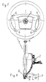
Figur 3 undFigur 4- ebenfalls eine Vorder- und eine Rückseite eines Lenkrads gemäß der Erfindung in anderer Ausführungsform und
Figur 5- eine Vorderseite eines erfindungsgemäßen Lenkrads in einer weiteren Ausführungsform und
Figur 6- einen Querschnitt des Lenkrads aus
Figur 5.
- Figure 1 and Figure 2
- a front and a rear of a steering wheel according to the invention,
- Figure 3 and Figure 4
- also a front and a rear of a steering wheel according to the invention in another embodiment and
- Figure 5
- a front of a steering wheel according to the invention in a further embodiment and
- Figure 6
- 3 shows a cross section of the steering wheel from FIG. 5.
Figur 1 zeigt die Vorderseite eines Lenkrads 1, bestehend aus einer Lenkradnabe 2,
vier Lenkradspeichen 3 und einem Lenkradkranz 4. Zwischen jeweils zwei Lenkradspeichen
3 ist an der Lenkradnabe 2 in Richtung zum Lenkradkranz 4 hin jeweils
eine Schaltereinrichtung 5 zum manuellen Schalten der Gangstufen eines nicht gezeichneten
Fahrzeuggetriebes angebracht. Die Schaltereinrichtungen 5 drehen sich
bei einer Lenkradbewegung mit dem Lenkrad 1 mit. Sie sind so in der Nähe des
Lenkradkranzes 4 angebracht, daß sie sich in Reichweite der nicht gezeichneten
Finger des nicht gezeichneten Fahrers befinden, wenn dieser das Lenkrad 1 in einer
Stellung für Geradeausfahrt hält. Zum sequentiellen Hochschalten des Fahrzeuggetriebes
kann der Fahrer einen Daumen seiner nicht gezeichneten am Lenkrad 1
befindlichen linken oder rechten Hand benutzen, indem er die linke oder rechte
Schaltereinrichtung 5 in eine von ihm weggerichtete Schaltrichtung bewegt. Bewegt
er einen anderen Finger der linken oder rechten Hand in die entgegengesetzte
Richtung, zu ihm hingerichtet, und betätigt dadurch die als Kippschalter ausgebildete
Schaltereinrichtung 5 von hinten (Figur 2), dann schaltet das Fahrzeuggetriebe
sequentiell zurück. Das heißt, bei jeder Betätigung der Schaltereinrichtung 5 wird um
eine Gangstufe zurückgeschaltet. Als Symbolik dafür ist in Figur 2 auf der Rückseite
des Lenkrads 1 ein Zeichensymbol ![]()
![]()
Die Ausführungsform der Betätigungseinrichtung zum Schalten der Gangstufen
eines Fahrzeuggetriebes, die in den Figuren 3 und 4 dargestellt ist, unterscheidet
sich von der in den Figuren 1 und 2 beschriebenen desweiteren dadurch, daß die
Anordnung der Schaltereinrichtungen 5 am Lenkrad 1 anders gewählt ist und daß
insgesamt vier Schaltereinrichtungen 5 zur Anwendung kommen. Außerdem
schaltet, wie gesagt, eine Betätigung einer der Schaltereinrichtungen 5 auf der Vorderseite
des Lenkrads 1, in Schaltrichtung vom Fahrer weg, das Fahrzeuggetriebe
sequentiell zurück, während eine Betätigung der Schaltereinrichtungen 5 auf der
Rückseite des Lenkrads 1, in Schaltrichtung zum Fahrer hin, das Fahrzeuggetriebe
sequentiell hochschaltet. Deshalb ist in Figur 3 auf den Schaltereinrichtungen 5 das
Zeichensymbol
Die weitere Ausführungsform der Betätigungseinrichtung in Figur 5 und Figur 6
zeichnet sich dadurch aus, daß jede Schaltereinrichtung 5 aus zwei selbstrückstellenden
Druckschaltern 6,7 besteht. Insgesamt sind vier Schaltereinrichtungen 5
gezeichnet, auf jeder Lenkradspeiche 3 eine. Die Betätigung in Schaltrichtung vom
Fahrer weg, jeweils eines Druckschalters 6 in Figur 5, gekennzeichnet mit dem
Zeichensymbol Minus, bewirkt jeweils das Zurückschalten des Fahrzeuggetriebes
um eine Gangstufe. Das sequentielle Zurückschalten kann wahlweise mit jedem der
Druckschalter 6 alleine bewerkstelligt werden oder mit allen Druckschaltern 6 in
wahlweiser Abwechslung. Einer der Druckschalter 7 zum Hochschalten der Gangstufen
des Fahrzeuggetriebes ist in Figur 6 sichtbar. Sie liegen auf der Rückseite
der Lenkradspeichen 3 und werden durch eine zum Fahrer hin gerichtete Bewegung
betätigt. Auch die Schaltereinrichtungen 5 dieser Ausführungsform, als Druckschalter
6,7, sind nahe dem Lenkradkranz 4 so angebracht, daß sie sich in Reichweite
der nicht gezeichneten Finger des Fahrers befinden, wenn dieser das Lenkrad
in einer Stellung für Geradeausfahrt hält.The further embodiment of the actuating device in FIG. 5 and FIG. 6
is characterized in that each
Bei allen in Figur 1 bis Figur 6 dargestellten Ausführungsformen der Erfindung wird
durch einen Lenkeinschlag zwar die Position der Schaltereinrichtungen 5 verändert,
aber nicht ihre Funktion, was die Schaltrichtungen für das Hoch- und Zurückschalten
betrifft. Deshalb werden solche Fehlschaltungen vermieden, die möglich sind bei
bekannten manuellen Betätigungseinrichtungen zum Schalten eines Fahrzeuggetriebes
am Lenkrad und darauf beruhen, daß sich bei einem Lenkeinschlag, insbesondere
um 180°, auch die Betätigungsrichtungen der Schaltereinrichtungen was
das Hoch- bzw. Zurückschalten betrifft ändern.In all of the embodiments of the invention illustrated in FIGS. 1 to 6
changed the position of the
Claims (5)
Applications Claiming Priority (2)
| Application Number | Priority Date | Filing Date | Title |
|---|---|---|---|
| DE19810375A DE19810375A1 (en) | 1998-03-10 | 1998-03-10 | Vehicle transmission actuation device on the steering wheel |
| DE19810375 | 1998-03-10 |
Publications (3)
| Publication Number | Publication Date |
|---|---|
| EP0941886A2 true EP0941886A2 (en) | 1999-09-15 |
| EP0941886A3 EP0941886A3 (en) | 2000-11-08 |
| EP0941886B1 EP0941886B1 (en) | 2003-08-27 |
Family
ID=7860421
Family Applications (1)
| Application Number | Title | Priority Date | Filing Date |
|---|---|---|---|
| EP99102517A Expired - Lifetime EP0941886B1 (en) | 1998-03-10 | 1999-02-10 | Device for motor vehicle gear shift arranged on the steering wheel |
Country Status (2)
| Country | Link |
|---|---|
| EP (1) | EP0941886B1 (en) |
| DE (2) | DE19810375A1 (en) |
Cited By (9)
| Publication number | Priority date | Publication date | Assignee | Title |
|---|---|---|---|---|
| EP1304507A1 (en) * | 2001-10-17 | 2003-04-23 | Mazda Motor Corporation | Manual gearshift device for automotive automatic transmission |
| DE10156668A1 (en) * | 2001-11-17 | 2003-05-28 | Bayerische Motoren Werke Ag | Connector system for operating e.g. power-assisted steering comprises two self-switching connectors mounted in housings in upper section of steering wheel rim |
| EP1211119A3 (en) * | 2000-12-01 | 2003-11-05 | Alps Electric Co., Ltd. | Vehicle-mounting steering switch |
| DE102009001940A1 (en) | 2009-03-27 | 2010-09-30 | Ford Global Technologies, LLC, Dearborn | Gear shift system, for a motor vehicle gearbox, has controls and shift levers at the steering wheel and rotating with it |
| DE102009027232A1 (en) | 2009-06-26 | 2010-12-30 | Ford-Werke Gmbh | Steering wheel switch module |
| DE102010000799A1 (en) | 2010-01-12 | 2011-07-14 | Ford Global Technologies, LLC, Mich. | Actuating device for switching of gear of vehicle drive, has switching unit attached at steering wheel, where switching unit has lever for sequential up shift and fall back of gear of vehicle drive |
| US8173917B2 (en) | 2008-04-30 | 2012-05-08 | Dr. Ing. H.C. F. Porsche Aktiengesellschaft | Actuating device on a vehicle steering wheel |
| CN101342868B (en) * | 2007-07-13 | 2012-06-27 | F.波尔希名誉工学博士公司 | Actuating device on a vehicle steering wheel |
| RU2515005C2 (en) * | 2008-11-27 | 2014-05-10 | ДЖИЭМ Глобал Текнолоджи Оперейшн ЛЛЦ | Device and method of control over automatic gearbox |
Families Citing this family (4)
| Publication number | Priority date | Publication date | Assignee | Title |
|---|---|---|---|---|
| DE102004021833A1 (en) * | 2004-05-04 | 2005-12-01 | Adam Opel Ag | Steering wheel for motor vehicle comprises has operating elements for adjustment of functioning states in vehicle, with each operating element constructed as rocker switch integrated into center strut |
| DE102005052492A1 (en) * | 2005-11-03 | 2007-05-10 | Bayerische Motoren Werke Ag | vehicle |
| DE102008022441A1 (en) | 2008-04-30 | 2009-11-05 | Dr. Ing. H.C. F. Porsche Aktiengesellschaft | Actuating device for railcar gearbox system for double clutch transmission at vehicle steering wheel of motor vehicle, has switching keys coupled with switching mechanism for switching gear speeds of double clutch transmission |
| DE102008022549A1 (en) | 2008-04-30 | 2009-11-05 | Dr. Ing. H.C. F. Porsche Aktiengesellschaft | Actuation device for switching double clutch-transmission of steering wheel of motor vehicle, has bracket arranged around one rotation axis in swivelable manner at connection elements and around another rotation axis at fixed support plate |
Citations (1)
| Publication number | Priority date | Publication date | Assignee | Title |
|---|---|---|---|---|
| EP0519528B1 (en) | 1991-06-15 | 1995-07-12 | Delphi France Automotive Systems | Transmission control module |
Family Cites Families (4)
| Publication number | Priority date | Publication date | Assignee | Title |
|---|---|---|---|---|
| DE9320309U1 (en) * | 1993-03-18 | 1994-03-31 | Porsche Ag | Motor vehicle with an actuator |
| DE4311852A1 (en) * | 1993-03-19 | 1994-09-22 | Bosch Gmbh Robert | Operating device for the manual actuation of the shift sequence of a vehicle transmission |
| US5365803A (en) * | 1993-07-13 | 1994-11-22 | Caterpillar Inc. | Steering and transmission shifting control device |
| DE4324788C2 (en) * | 1993-07-23 | 1996-03-28 | Porsche Ag | Motor vehicle with an actuator on the steering wheel |
-
1998
- 1998-03-10 DE DE19810375A patent/DE19810375A1/en not_active Withdrawn
-
1999
- 1999-02-10 EP EP99102517A patent/EP0941886B1/en not_active Expired - Lifetime
- 1999-02-10 DE DE59906720T patent/DE59906720D1/en not_active Expired - Lifetime
Patent Citations (1)
| Publication number | Priority date | Publication date | Assignee | Title |
|---|---|---|---|---|
| EP0519528B1 (en) | 1991-06-15 | 1995-07-12 | Delphi France Automotive Systems | Transmission control module |
Cited By (11)
| Publication number | Priority date | Publication date | Assignee | Title |
|---|---|---|---|---|
| EP1211119A3 (en) * | 2000-12-01 | 2003-11-05 | Alps Electric Co., Ltd. | Vehicle-mounting steering switch |
| EP1304507A1 (en) * | 2001-10-17 | 2003-04-23 | Mazda Motor Corporation | Manual gearshift device for automotive automatic transmission |
| US6948399B2 (en) | 2001-10-17 | 2005-09-27 | Mazda Motor Corporation | Manual gearshift device for automotive automatic transmission |
| US7131347B2 (en) | 2001-10-17 | 2006-11-07 | Mazda Motor Corporation | Manual gearshift device for automotive automatic transmission |
| DE10156668A1 (en) * | 2001-11-17 | 2003-05-28 | Bayerische Motoren Werke Ag | Connector system for operating e.g. power-assisted steering comprises two self-switching connectors mounted in housings in upper section of steering wheel rim |
| CN101342868B (en) * | 2007-07-13 | 2012-06-27 | F.波尔希名誉工学博士公司 | Actuating device on a vehicle steering wheel |
| US8173917B2 (en) | 2008-04-30 | 2012-05-08 | Dr. Ing. H.C. F. Porsche Aktiengesellschaft | Actuating device on a vehicle steering wheel |
| RU2515005C2 (en) * | 2008-11-27 | 2014-05-10 | ДЖИЭМ Глобал Текнолоджи Оперейшн ЛЛЦ | Device and method of control over automatic gearbox |
| DE102009001940A1 (en) | 2009-03-27 | 2010-09-30 | Ford Global Technologies, LLC, Dearborn | Gear shift system, for a motor vehicle gearbox, has controls and shift levers at the steering wheel and rotating with it |
| DE102009027232A1 (en) | 2009-06-26 | 2010-12-30 | Ford-Werke Gmbh | Steering wheel switch module |
| DE102010000799A1 (en) | 2010-01-12 | 2011-07-14 | Ford Global Technologies, LLC, Mich. | Actuating device for switching of gear of vehicle drive, has switching unit attached at steering wheel, where switching unit has lever for sequential up shift and fall back of gear of vehicle drive |
Also Published As
| Publication number | Publication date |
|---|---|
| DE19810375A1 (en) | 1999-09-16 |
| EP0941886B1 (en) | 2003-08-27 |
| DE59906720D1 (en) | 2003-10-02 |
| EP0941886A3 (en) | 2000-11-08 |
Similar Documents
| Publication | Publication Date | Title |
|---|---|---|
| EP0635388B1 (en) | Motor vehicle with control device mounted on the steering wheel | |
| EP0444250B1 (en) | Shift device for automatic transmission | |
| DE60009749T2 (en) | Control device in a vehicle | |
| DE102010024388B4 (en) | Device for operating functions of a motor vehicle | |
| EP0941886B1 (en) | Device for motor vehicle gear shift arranged on the steering wheel | |
| DE3001935C2 (en) | Switching device for a gearbox | |
| EP0999383A2 (en) | Gear-shift device for an automatic gearbox of a motor vehicle | |
| DE4311852A1 (en) | Operating device for the manual actuation of the shift sequence of a vehicle transmission | |
| WO2004037597A1 (en) | Drive train comprising a device for selecting driving mode ranges of an automated manual transmission or automatic transmission of a motor vehicle | |
| DE19737296C2 (en) | Automatic switching device of a gear change transmission with a manual selector | |
| DE19702788B4 (en) | Device for switching a motorcycle transmission | |
| DE3941665A1 (en) | Vehicle with steering-wheel-mounted automatic transmission control - affording choices of more or less economical driving and manual override of automatic gear ratio selection | |
| DE4305903A1 (en) | Gearshift device for a motor vehicle automatic transmission | |
| EP1104516A1 (en) | Device for changing the gears of an automatic transmission | |
| DE3337930C2 (en) | Selector switch in a shift control for automatic transmissions | |
| DE3742600C2 (en) | ||
| DE102019122975A1 (en) | TRANSMISSION SYSTEM WITH AN AUTOMATIC MANUAL TRANSMISSION | |
| DE102014101181B4 (en) | Shift lever arrangement for selecting a driving mode and gear selection for an automatic transmission and method for actuating the shift lever arrangement | |
| EP1167831B1 (en) | Actuating device for controlling shifting of vehicle transmission | |
| DE60006457T2 (en) | Compact gearbox with swivel feet for operating shift forks | |
| DE102009001940A1 (en) | Gear shift system, for a motor vehicle gearbox, has controls and shift levers at the steering wheel and rotating with it | |
| EP3553626A1 (en) | Operating device | |
| DE19941013A1 (en) | Switching device for controlling an automatic transmission of a motor vehicle | |
| DE19961375A1 (en) | Gear changing device for automobile automatic transmission has movement of rotary gear selection element correlated with selected gear | |
| DE10156668A1 (en) | Connector system for operating e.g. power-assisted steering comprises two self-switching connectors mounted in housings in upper section of steering wheel rim |
Legal Events
| Date | Code | Title | Description |
|---|---|---|---|
| PUAI | Public reference made under article 153(3) epc to a published international application that has entered the european phase |
Free format text: ORIGINAL CODE: 0009012 |
|
| AK | Designated contracting states |
Kind code of ref document: A2 Designated state(s): DE FR GB IT |
|
| AX | Request for extension of the european patent |
Free format text: AL;LT;LV;MK;RO;SI |
|
| PUAL | Search report despatched |
Free format text: ORIGINAL CODE: 0009013 |
|
| AK | Designated contracting states |
Kind code of ref document: A3 Designated state(s): AT BE CH CY DE DK ES FI FR GB GR IE IT LI LU MC NL PT SE |
|
| AX | Request for extension of the european patent |
Free format text: AL;LT;LV;MK;RO;SI |
|
| RIC1 | Information provided on ipc code assigned before grant |
Free format text: 7B 60K 20/06 A, 7B 60R 16/00 B, 7F 16H 59/02 B |
|
| 17P | Request for examination filed |
Effective date: 20010118 |
|
| AKX | Designation fees paid |
Free format text: DE FR GB IT |
|
| 17Q | First examination report despatched |
Effective date: 20020624 |
|
| GRAH | Despatch of communication of intention to grant a patent |
Free format text: ORIGINAL CODE: EPIDOS IGRA |
|
| GRAH | Despatch of communication of intention to grant a patent |
Free format text: ORIGINAL CODE: EPIDOS IGRA |
|
| GRAA | (expected) grant |
Free format text: ORIGINAL CODE: 0009210 |
|
| AK | Designated contracting states |
Designated state(s): DE FR GB IT |
|
| REG | Reference to a national code |
Ref country code: GB Ref legal event code: FG4D Free format text: NOT ENGLISH |
|
| GBT | Gb: translation of ep patent filed (gb section 77(6)(a)/1977) | ||
| REF | Corresponds to: |
Ref document number: 59906720 Country of ref document: DE Date of ref document: 20031002 Kind code of ref document: P |
|
| ET | Fr: translation filed | ||
| PLBE | No opposition filed within time limit |
Free format text: ORIGINAL CODE: 0009261 |
|
| STAA | Information on the status of an ep patent application or granted ep patent |
Free format text: STATUS: NO OPPOSITION FILED WITHIN TIME LIMIT |
|
| 26N | No opposition filed |
Effective date: 20040528 |
|
| REG | Reference to a national code |
Ref country code: FR Ref legal event code: PLFP Year of fee payment: 18 |
|
| PGFP | Annual fee paid to national office [announced via postgrant information from national office to epo] |
Ref country code: DE Payment date: 20160229 Year of fee payment: 18 |
|
| REG | Reference to a national code |
Ref country code: FR Ref legal event code: PLFP Year of fee payment: 19 |
|
| PGFP | Annual fee paid to national office [announced via postgrant information from national office to epo] |
Ref country code: FR Payment date: 20170220 Year of fee payment: 19 |
|
| PGFP | Annual fee paid to national office [announced via postgrant information from national office to epo] |
Ref country code: GB Payment date: 20170221 Year of fee payment: 19 |
|
| PGFP | Annual fee paid to national office [announced via postgrant information from national office to epo] |
Ref country code: IT Payment date: 20170217 Year of fee payment: 19 |
|
| REG | Reference to a national code |
Ref country code: DE Ref legal event code: R119 Ref document number: 59906720 Country of ref document: DE |
|
| PG25 | Lapsed in a contracting state [announced via postgrant information from national office to epo] |
Ref country code: DE Free format text: LAPSE BECAUSE OF NON-PAYMENT OF DUE FEES Effective date: 20170901 |
|
| GBPC | Gb: european patent ceased through non-payment of renewal fee |
Effective date: 20180210 |
|
| REG | Reference to a national code |
Ref country code: FR Ref legal event code: ST Effective date: 20181031 |
|
| PG25 | Lapsed in a contracting state [announced via postgrant information from national office to epo] |
Ref country code: IT Free format text: LAPSE BECAUSE OF NON-PAYMENT OF DUE FEES Effective date: 20180210 Ref country code: GB Free format text: LAPSE BECAUSE OF NON-PAYMENT OF DUE FEES Effective date: 20180210 Ref country code: FR Free format text: LAPSE BECAUSE OF NON-PAYMENT OF DUE FEES Effective date: 20180228 |