EP0940597A1 - Druckmittelbeaufschlagbare Schaltkupplung - Google Patents
Druckmittelbeaufschlagbare Schaltkupplung Download PDFInfo
- Publication number
- EP0940597A1 EP0940597A1 EP99103645A EP99103645A EP0940597A1 EP 0940597 A1 EP0940597 A1 EP 0940597A1 EP 99103645 A EP99103645 A EP 99103645A EP 99103645 A EP99103645 A EP 99103645A EP 0940597 A1 EP0940597 A1 EP 0940597A1
- Authority
- EP
- European Patent Office
- Prior art keywords
- clutch
- pressure
- ring
- clutch according
- shaft
- Prior art date
- Legal status (The legal status is an assumption and is not a legal conclusion. Google has not performed a legal analysis and makes no representation as to the accuracy of the status listed.)
- Granted
Links
- 238000010168 coupling process Methods 0.000 title claims description 18
- 230000008878 coupling Effects 0.000 title claims description 16
- 238000005859 coupling reaction Methods 0.000 title claims description 16
- 239000013013 elastic material Substances 0.000 claims abstract description 3
- 238000007789 sealing Methods 0.000 claims description 8
- 230000005540 biological transmission Effects 0.000 description 3
- 238000004519 manufacturing process Methods 0.000 description 2
- 230000000694 effects Effects 0.000 description 1
- 230000002349 favourable effect Effects 0.000 description 1
- 230000002706 hydrostatic effect Effects 0.000 description 1
- 238000003780 insertion Methods 0.000 description 1
- 230000037431 insertion Effects 0.000 description 1
- 230000007935 neutral effect Effects 0.000 description 1
- 230000036316 preload Effects 0.000 description 1
- 239000005871 repellent Substances 0.000 description 1
- 238000000926 separation method Methods 0.000 description 1
Images
Classifications
-
- F—MECHANICAL ENGINEERING; LIGHTING; HEATING; WEAPONS; BLASTING
- F16—ENGINEERING ELEMENTS AND UNITS; GENERAL MEASURES FOR PRODUCING AND MAINTAINING EFFECTIVE FUNCTIONING OF MACHINES OR INSTALLATIONS; THERMAL INSULATION IN GENERAL
- F16H—GEARING
- F16H63/00—Control outputs from the control unit to change-speed- or reversing-gearings for conveying rotary motion or to other devices than the final output mechanism
- F16H63/02—Final output mechanisms therefor; Actuating means for the final output mechanisms
- F16H63/30—Constructional features of the final output mechanisms
- F16H63/3023—Constructional features of the final output mechanisms the final output mechanisms comprising elements moved by fluid pressure
-
- F—MECHANICAL ENGINEERING; LIGHTING; HEATING; WEAPONS; BLASTING
- F16—ENGINEERING ELEMENTS AND UNITS; GENERAL MEASURES FOR PRODUCING AND MAINTAINING EFFECTIVE FUNCTIONING OF MACHINES OR INSTALLATIONS; THERMAL INSULATION IN GENERAL
- F16D—COUPLINGS FOR TRANSMITTING ROTATION; CLUTCHES; BRAKES
- F16D25/00—Fluid-actuated clutches
- F16D25/06—Fluid-actuated clutches in which the fluid actuates a piston incorporated in, i.e. rotating with the clutch
- F16D25/061—Fluid-actuated clutches in which the fluid actuates a piston incorporated in, i.e. rotating with the clutch the clutch having interengaging clutch members
-
- F—MECHANICAL ENGINEERING; LIGHTING; HEATING; WEAPONS; BLASTING
- F16—ENGINEERING ELEMENTS AND UNITS; GENERAL MEASURES FOR PRODUCING AND MAINTAINING EFFECTIVE FUNCTIONING OF MACHINES OR INSTALLATIONS; THERMAL INSULATION IN GENERAL
- F16D—COUPLINGS FOR TRANSMITTING ROTATION; CLUTCHES; BRAKES
- F16D25/00—Fluid-actuated clutches
- F16D25/10—Clutch systems with a plurality of fluid-actuated clutches
Definitions
- the invention relates to a clutch that can be pressurized, in which a Coupling ring with teeth for rotation and axially displaceable on a shaft Transmission of the driving force through a pressure medium that can be introduced into a pressure chamber Can be brought into engagement with a corresponding coupling ring with corresponding toothing.
- a clutch that can be acted upon by a pressure medium is known from EP 0 276 255 known.
- the Couplings are form-fitting tooth couplings in the special form of face gear formed in which the tooth profiles of the parts to be coupled in the axial direction are arranged. Due to the axially arranged teeth, the switching path of the to be coupled Parts are kept very short because of the specific pressure on the teeth due to the high Surface area of the teeth can be kept low.
- the task is solved by the seals for sealing the pressure chamber so are arranged so that they are not in constant contact with the wall to be sealed Pressure chamber.
- the solution according to the invention can also consist in that a movable Seal can be placed on an adjacent wall during a coupling process and / or a movable wall can be placed on a seal. With one Arrangement of the sealing elements prevents additional frictional forces in the clutch Face teeth can be given a desired favorable tooth angle, the automatic one Switching off remains safe and the dimensions of the couplings can be kept very small. Further advantageous configurations and variants of the claimed Invention can be found in the subclaims, to which reference is made in this regard.
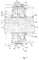
- FIG. 1 is a Cross section through a clutch according to the invention, which can be acted upon by pressure medium 2 to see, namely in the form of a double clutch.
- the elements to be switched on the Shaft 4 are the gears 6, 8 as idler gears, which are mounted on the shaft 4 via bearings 10, 12 are rotatably arranged. Axially arranged on each side of the gears 6, 8 Teeth 14, 16 attached.
- the actual clutch is between the two gears 6, 8 2 arranged. It essentially consists of a driver, which preferably is arranged on the shaft 4 in a manner fixed against relative rotation but axially displaceable. Of the Driver is essentially formed by the coupling rings 18, 20 and the locking ring 22.
- the driver 18, 20, 22 engages around the pressure spaces 24a, 24b and one therein located, supported on the shaft 4 pressure ring 26 which is axially immovable on the Shaft 4 with shaft locking rings 28 is arranged.
- the pressure chamber 24a is thus laterally from the shaft 4, the pressure ring 26, the locking ring 22 and the coupling ring 20 bounded, while the pressure chamber 24b by the shaft 4, the pressure ring 26, the locking ring 22 and the coupling ring 18 is bounded.
- the clutch must be operated in order to apply a driving force to one of the gears 6, 8 conduct. This is done by leading a pressure medium into a pressure chamber 24a, 24b. If, for example, the gearwheel 8 is to be switched on, pressure medium must be in the pressure chamber 24a arrive. Switching is preferably carried out with an at least approximate one Speed of the shaft 4 and the gear 8. To switch on the gear 8 is a Pressure medium is given through the channel 30 in the pressure chamber 24a. The driver 18, 20, 22 moves due to the pressure building up in the pressure chamber 24a and the hydrostatic acting pressure medium in the direction of arrow M, and the teeth 16, 32 come into engagement with each other.
- the amount of pressure medium supplied may be greater than that emerging through the gaps and teeth Leakage oil quantities.
- the amount of pressure medium supplied must be sufficient in order to be able to fill the growing pressure chamber 24a with pressure medium.
- the depth of the Tooth profile and the stroke that the driver 18, 20, 22 must travel to To bring gears 16, 32 securely into engagement with one another should be advantageous be coordinated that the driver 18, 20, 22 approximately its end stop achieved when the tooth profiles are sufficiently safe for transmission of drive power are interlinked.
- the toothings 16, 32 are designed as face teeth, the flanks of which one Show trapezoidal toothing, which has a force-repellent component.
- Such Gearing loosens automatically when the pressure chamber 24a, 24b is depressurized. Only now, when the teeth 16, 32 are sufficiently deeply toothed in the area of the end stop of the driver 18, 20, 22, the outer surface of the coupling ring 20 on the Seal 38a pressed, and that located on the inside of the coupling ring 18 Seal 40a seals the gap 36. The pressure chamber 24a is thus almost complete sealed.
- the seals 38a, 38b, 40a, 40b are in suitably shaped grooves, For example, dovetail grooves are arranged, in which they are at the appropriate Can keep cross-sectional shape itself.
- the seals 38a, 38b, 40a, 40b should be preferred be made of elastic material.
- gear 6 If gear 6 is to be activated, pressure medium is applied to channel 42.
- the Operation is analogous to the operation described above, only with the Difference that the driver 18, 20, 22 now moves in the N direction and finally the seals 38b, 40b seal the pressure chamber 24b and the teeth 14, 50 interlock.
- the channels 30, 42 are depressurized.
- a locking system consisting of springs 44 and balls 46, which are in one on the inside of the locking ring 22 circumferential groove 48 can be a safe neutral position the clutch 2 achieved.
- This ball / spring system also supports a fast Switching off a coupled gear 6, 8 when the clutch is depressurized.
- the driver 18, 20, 22 When designing the clutch 2 as a double clutch, it is advantageous if the driver 18, 20, 22 to simplify production from two identical parts 18, 20 exists, which together with the locking ring 22 of screws 52 or in the Effect comparable fasteners are held together.
Landscapes
- Engineering & Computer Science (AREA)
- General Engineering & Computer Science (AREA)
- Mechanical Engineering (AREA)
- Physics & Mathematics (AREA)
- Fluid Mechanics (AREA)
- Mechanical Operated Clutches (AREA)
Abstract
Description
Claims (11)
- Druckmittelbeaufschlagbare Schaltkupplung, bei der ein drehfest und axial auf einer Welle verschiebbarer Kupplungsring mit einer Verzahnung zur Übertragung der Antriebskraft durch ein in einen Druckraum einleitbares Druckmittel in Eingriff bringbar ist mit einem entsprechenden Kupplungsring mit entsprechender Verzahnung,
dadurch gekennzeichnet,
daß die Dichtungen (38a, 38b, 40a, 40b) zur Abdichtung des Druckraumes (24a, 24b) so angeordnet sind, daß sie nicht ständig in Kontakt sind mit der abzudichtenden Wandung (4, 18, 20, 22) des Druckraumes (24a, 24b). - Druckmittelbeaufschlagbare Schaltkupplung, bei der ein drehfest und axial auf einer Welle verschiebbarer Kupplungsring mit einer Verzahnung zur Übertragung der Antriebskraft durch ein in einen Druckraum einleitbares Druckmittel in Eingriff bringbar ist mit einem entsprechenden Kupplungsring mit entsprechender Verzahnung,
dadurch gekennzeichnet,
daß eine bewegbare Dichtung (40a, 40b) während eines Kupplungsvorganges aufeine benachbarte Wandung (18, 20) aufsetzbar ist und/oder eine bewegbare Wandung (18, 20) auf eine Dichtung (38a, 38b) aufsetzbar ist. - Schaltkupplung nach Anspruch 1 oder 2,
dadurch gekennzeichnet,
daß die Dichtelemente (38a, 38b, 40a, 40b) selbsthaltend in Nuten angeordnet sind. - Schaltkupplung nach Anspruch 1, 2 oder 3,
dadurch gekennzeichnet,
daß die Dichtelemente (38a, 38b, 40a, 40b) aus elastischem Material hergestellt sind. - Schaltkupplung nach einem oder mehreren der Ansprüche 1 bis 4,
dadurch gekennzeichnet,
daß der Druckring (26) mit einem Spiel auf der Welle (4) montiert ist. - Schaltkupplung nach einem oder mehreren der Ansprüche 1 bis 5,
dadurch gekennzeichnet,
daß zwischen dem Druckring (26) und der Welle (4) eine zusätzliche Dichtung (11) angeordnet ist. - Schaltkupplung nach einem oder mehreren der Ansprüche 1 bis 6,
dadurch gekennzeichnet,
daß das Antriebsdrehmoment über Kurzverzahnungen (34) von der Welle (4) auf die Kupplungsringe (18, 20) übertragbar ist. - Schaltkupplung nach einem oder mehreren der Ansprüche 1 bis 7,
dadurch gekennzeichnet,
daß das Antriebsdrehmoment über planverzahnte Verzahnungen (16/32, 14/50) auf die zuschaltbaren Zahnräder (6, 8) übertragen wird. - Schaltkupplung nach einem oder mehreren der Ansprüche 1 bis 8,
dadurch gekennzeichnet,
daß die Kupplungsringe (18, 20) aus identischen Teilen bestehen. - Schaltkupplung nach einem oder mehreren der Ansprüche 1 bis 9,
dadurch gekennzeichnet,
daß die Kupplungsringe (18, 20) und der Schließring (22) durch Befestigungsmittel miteinander verbunden sind. - Schaltkupplung nach einem oder mehreren der Ansprüche 1 bis 10,
dadurch gekennzeichnet,
daß zur Mittenzentrierung und/oder zum beschleunigten Ausschalten des Mitnehmers (18, 20, 22) ein Kugel-Federrastsystem (44, 46, 48) verwendet ist.
Applications Claiming Priority (2)
| Application Number | Priority Date | Filing Date | Title |
|---|---|---|---|
| DE19808855A DE19808855C1 (de) | 1998-03-03 | 1998-03-03 | Druckmittelbeaufschlagbare Schaltkupplung |
| DE19808855 | 1998-03-03 |
Publications (2)
| Publication Number | Publication Date |
|---|---|
| EP0940597A1 true EP0940597A1 (de) | 1999-09-08 |
| EP0940597B1 EP0940597B1 (de) | 2002-05-15 |
Family
ID=7859457
Family Applications (1)
| Application Number | Title | Priority Date | Filing Date |
|---|---|---|---|
| EP99103645A Expired - Lifetime EP0940597B1 (de) | 1998-03-03 | 1999-02-25 | Druckmittelbeaufschlagbare Schaltkupplung |
Country Status (3)
| Country | Link |
|---|---|
| US (1) | US6076643A (de) |
| EP (1) | EP0940597B1 (de) |
| DE (2) | DE19808855C1 (de) |
Cited By (1)
| Publication number | Priority date | Publication date | Assignee | Title |
|---|---|---|---|---|
| CN102906437A (zh) * | 2010-03-26 | 2013-01-30 | 敏思工业公司 | 包括机电致动器子组件的超速联接和控制组件 |
Families Citing this family (11)
| Publication number | Priority date | Publication date | Assignee | Title |
|---|---|---|---|---|
| DE10039813C1 (de) * | 2000-08-16 | 2002-02-14 | Voith Turbo Kg | Maschinensatz mit einem Antrieb und einer Arbeitsmaschine |
| US6814201B2 (en) * | 2003-02-13 | 2004-11-09 | Borgwarner, Inc. | Bi-directional axially applied pawl clutch assembly |
| DE20314476U1 (de) * | 2003-09-18 | 2004-04-01 | Jegel, Franz Peter, Ing. | Gangstufenschaltgetriebe mit Klauenschaltung |
| DE102004057850A1 (de) * | 2004-12-01 | 2006-06-08 | Zf Friedrichshafen Ag | Schaltvorrichtung |
| DE102006037210A1 (de) * | 2006-08-09 | 2008-02-14 | Zf Friedrichshafen Ag | Schalteinrichtung für ein Getriebe eines Kraftfahrzeugs |
| DE102006049280A1 (de) * | 2006-10-19 | 2008-04-30 | Zf Friedrichshafen Ag | Vorrichtung zum Betätigen wenigstens eines Schaltelementes |
| BRPI0822871B1 (pt) * | 2008-07-03 | 2020-09-15 | Deere & Company | Transmissão para um veículo, e, método para operar uma transmissão em um veículo |
| DE202009003671U1 (de) | 2009-03-17 | 2009-05-28 | Getrag Getriebe- Und Zahnradfabrik Hermann Hagenmeyer Gmbh & Cie Kg | Wellenanordnung für ein Getriebe |
| AT511147A1 (de) * | 2011-02-17 | 2012-09-15 | Avl List Gmbh | Getriebe mit zumindest einer welle |
| JP2016188691A (ja) * | 2015-03-30 | 2016-11-04 | 株式会社 神崎高級工機製作所 | クラッチ機構 |
| US11498418B2 (en) | 2019-09-30 | 2022-11-15 | Deere & Company | Power take-off shaft system and agricultural vehicle |
Citations (5)
| Publication number | Priority date | Publication date | Assignee | Title |
|---|---|---|---|---|
| GB179700A (en) * | 1921-02-19 | 1922-05-18 | British Leyland Motor Corp | Improvements in and relating to variable speed gears |
| US3303914A (en) * | 1964-12-30 | 1967-02-14 | Borg Warner | Double modulated twin acting hydraulic clutch |
| US4482039A (en) * | 1981-09-16 | 1984-11-13 | The Garrett Corporation | Pneumatic quick disconnect apparatus and methods |
| WO1988000661A1 (fr) * | 1986-07-23 | 1988-01-28 | Michael Meyerle | EMBRAYAGE DE CHANGEMENT DE VITESSE, EN PARTICULIER POUR BOîTES AUTOMATIQUES DE VEHICULES A MOTEUR |
| DE4220622A1 (de) * | 1992-06-24 | 1994-01-05 | Gerhard Fuehrer | Pneumatischer Schaltzylinder |
Family Cites Families (17)
| Publication number | Priority date | Publication date | Assignee | Title |
|---|---|---|---|---|
| US2253578A (en) * | 1939-04-20 | 1941-08-26 | Carl D Peterson | Synchronizing clutch |
| US3106999A (en) * | 1960-09-12 | 1963-10-15 | Twin Disc Clutch Co | Hydraulically operated clutch mechanism |
| US3098550A (en) * | 1961-10-12 | 1963-07-23 | Allis Chalmers Mfg Co | Double acting clutch |
| US3199648A (en) * | 1963-11-26 | 1965-08-10 | Allis Chalmers Mfg Co | Fluid transfer type clutch actuator |
| US3362481A (en) * | 1966-01-13 | 1968-01-09 | Twin Disc Inc | Hydraulically operated friction clutch having a dump valve |
| DE1301715B (de) * | 1966-04-26 | 1969-08-21 | Schottel Werft | Hydraulisches Gestaenge zum Betaetigen eines in einem Zylinder gefuehrten Kolbens |
| GB1169202A (en) * | 1966-04-29 | 1969-10-29 | Coventry Gauge & Tool Co Ltd | Friction Clutch Operating Mechanism |
| DE2540191C3 (de) * | 1975-09-10 | 1981-08-13 | Zahnradfabrik Friedrichshafen Ag, 7990 Friedrichshafen | Druckmittelbetätigte Lamellenkupplung mit stehendem Ringzylinder |
| DE2720679C2 (de) * | 1977-05-07 | 1986-09-18 | Vulkan Kupplungs- Und Getriebebau, Bernhard Hackforth Gmbh & Co Kg, 4690 Herne | Wellenkupplung mit Überlastsicherung |
| US4153148A (en) * | 1977-06-02 | 1979-05-08 | D. A. B. Industries, Inc. | Clutch with replacable disc and motor assemblies |
| DE2740658C3 (de) * | 1977-09-09 | 1980-08-28 | Jagenberg-Werke Ag, 4000 Duesseldorf | Formschlussige Kupplung zwischen Etikettiermaschine und einer mit einem Antrieb versehenen Füllmaschine |
| AU515278B2 (en) * | 1978-08-07 | 1981-03-26 | Cummins Engine Company Inc. | Fan drive |
| JPS57180284A (en) * | 1981-04-30 | 1982-11-06 | Nippon Telegr & Teleph Corp <Ntt> | Picture communication system |
| AT386871B (de) * | 1984-04-13 | 1988-10-25 | Steyr Daimler Puch Ag | Kupplungsvorrichtung fuer unter last schaltbare wechselgetriebe |
| US5035310A (en) * | 1986-07-23 | 1991-07-30 | Michael Meyerle | Clutch, particularly for automatic transmission for automotive vehicles |
| US4934500A (en) * | 1989-09-11 | 1990-06-19 | Horton Manufacturing Co., Inc. | Fluid pressure releasing device for overload apparatus |
| DE59207307D1 (de) * | 1991-04-10 | 1996-11-14 | Hoerbiger Gmbh | Synchronisierungseinrichtung |
-
1998
- 1998-03-03 DE DE19808855A patent/DE19808855C1/de not_active Expired - Fee Related
-
1999
- 1999-02-25 DE DE59901433T patent/DE59901433D1/de not_active Expired - Lifetime
- 1999-02-25 EP EP99103645A patent/EP0940597B1/de not_active Expired - Lifetime
- 1999-03-01 US US09/258,960 patent/US6076643A/en not_active Expired - Fee Related
Patent Citations (6)
| Publication number | Priority date | Publication date | Assignee | Title |
|---|---|---|---|---|
| GB179700A (en) * | 1921-02-19 | 1922-05-18 | British Leyland Motor Corp | Improvements in and relating to variable speed gears |
| US3303914A (en) * | 1964-12-30 | 1967-02-14 | Borg Warner | Double modulated twin acting hydraulic clutch |
| US4482039A (en) * | 1981-09-16 | 1984-11-13 | The Garrett Corporation | Pneumatic quick disconnect apparatus and methods |
| WO1988000661A1 (fr) * | 1986-07-23 | 1988-01-28 | Michael Meyerle | EMBRAYAGE DE CHANGEMENT DE VITESSE, EN PARTICULIER POUR BOîTES AUTOMATIQUES DE VEHICULES A MOTEUR |
| EP0276255A1 (de) | 1986-07-23 | 1988-08-03 | Michael Meyerle | Schaltkupplung, insbesondere für automatisch schaltbare kraftfahrzeuggetriebe. |
| DE4220622A1 (de) * | 1992-06-24 | 1994-01-05 | Gerhard Fuehrer | Pneumatischer Schaltzylinder |
Cited By (2)
| Publication number | Priority date | Publication date | Assignee | Title |
|---|---|---|---|---|
| CN102906437A (zh) * | 2010-03-26 | 2013-01-30 | 敏思工业公司 | 包括机电致动器子组件的超速联接和控制组件 |
| CN102906437B (zh) * | 2010-03-26 | 2015-05-13 | 敏思工业公司 | 包括机电致动器子组件的超速联接和控制组件 |
Also Published As
| Publication number | Publication date |
|---|---|
| US6076643A (en) | 2000-06-20 |
| EP0940597B1 (de) | 2002-05-15 |
| DE19808855C1 (de) | 2000-03-09 |
| DE59901433D1 (de) | 2002-06-20 |
Similar Documents
| Publication | Publication Date | Title |
|---|---|---|
| AT396008B (de) | Stufenlos verstellbares kegelscheibengetriebe | |
| EP0248899B1 (de) | Stufenschaltgetriebe | |
| DE19808855C1 (de) | Druckmittelbeaufschlagbare Schaltkupplung | |
| DE2619898A1 (de) | Stufenloses geschwindigkeitswechselgetriebe | |
| DE10323198B4 (de) | Planetengetriebevorrichtung für ein Fahrzeug, welche eine mittels Rückhaltering ausgestattete Kupplungstrommel aufweist | |
| AT510922B1 (de) | Getriebeanordnung zur variablen drehmomentverteilung | |
| DE4007506C1 (de) | ||
| WO2010057456A1 (de) | Fahrzeuggetriebe mit stufenlos veränderbarer übersetzung | |
| WO2007138002A1 (de) | Einrichtung zur axialeinstellung wenigstens eines lamellenschaltelementes | |
| DE19961275C2 (de) | Automatgetriebe für ein Kraftfahrzeug | |
| DE2725039A1 (de) | Sperrsynchronisierung fuer wechselgetriebe von kraftfahrzeugen, insbesondere von nutzfahrzeugen | |
| DE3928816A1 (de) | Automatisches getriebe | |
| DE532386C (de) | Zweigangwechselgetriebe, insbesondere fuer Kraftfahrzeuge | |
| EP0071596B1 (de) | Lastschaltgetriebe | |
| DE3527401A1 (de) | Stufenschaltgetriebe, insbesondere fuer kraftfahrzeuge | |
| WO2010142372A1 (de) | Getriebe mit zumindest zwei unterschiedlichen übersetzungen und verfahren zum betreiben dieses getriebes | |
| DE19648124A1 (de) | Planetenträger eines Planetengetriebes | |
| DE2903564C3 (de) | Stufenloses fliehkraftgeregeltes Verbundumlaufrädergetriebe | |
| DE10347402B4 (de) | Getriebe zum Übertragen einer Drehbewegung mit stufenlos veränderlichem Übersetzungsverhältnis | |
| DE680351C (de) | Schaltbares Luftschraubengetriebe mit Druckoelsteuerung | |
| DE854734C (de) | Stufenloses Getriebe | |
| DE3324434C2 (de) | Planetenradgetriebe | |
| DE1450818C (de) | Untersetzungs- und Wendegetriebe fur hydrodynamische Drehmomentwandler | |
| DE1550895C (de) | Hydraulische Schalteinrichtung fur ein Zahnrader Wechselgetriebe mit Ringkupplungen in den Radern | |
| DE8522057U1 (de) | Stufenschaltgetriebe, insbesondere für Kraftfahrzeuge |
Legal Events
| Date | Code | Title | Description |
|---|---|---|---|
| PUAI | Public reference made under article 153(3) epc to a published international application that has entered the european phase |
Free format text: ORIGINAL CODE: 0009012 |
|
| AK | Designated contracting states |
Kind code of ref document: A1 Designated state(s): DE FR GB IT SE |
|
| AX | Request for extension of the european patent |
Free format text: AL;LT;LV;MK;RO;SI |
|
| 17P | Request for examination filed |
Effective date: 20000308 |
|
| AKX | Designation fees paid |
Free format text: DE FR GB IT SE |
|
| 17Q | First examination report despatched |
Effective date: 20000711 |
|
| GRAG | Despatch of communication of intention to grant |
Free format text: ORIGINAL CODE: EPIDOS AGRA |
|
| GRAG | Despatch of communication of intention to grant |
Free format text: ORIGINAL CODE: EPIDOS AGRA |
|
| GRAH | Despatch of communication of intention to grant a patent |
Free format text: ORIGINAL CODE: EPIDOS IGRA |
|
| GRAH | Despatch of communication of intention to grant a patent |
Free format text: ORIGINAL CODE: EPIDOS IGRA |
|
| GRAA | (expected) grant |
Free format text: ORIGINAL CODE: 0009210 |
|
| AK | Designated contracting states |
Kind code of ref document: B1 Designated state(s): DE FR GB IT SE |
|
| PG25 | Lapsed in a contracting state [announced via postgrant information from national office to epo] |
Ref country code: IT Free format text: LAPSE BECAUSE OF FAILURE TO SUBMIT A TRANSLATION OF THE DESCRIPTION OR TO PAY THE FEE WITHIN THE PRESCRIBED TIME-LIMIT;WARNING: LAPSES OF ITALIAN PATENTS WITH EFFECTIVE DATE BEFORE 2007 MAY HAVE OCCURRED AT ANY TIME BEFORE 2007. THE CORRECT EFFECTIVE DATE MAY BE DIFFERENT FROM THE ONE RECORDED. Effective date: 20020515 |
|
| REG | Reference to a national code |
Ref country code: GB Ref legal event code: FG4D Free format text: NOT ENGLISH |
|
| REF | Corresponds to: |
Ref document number: 59901433 Country of ref document: DE Date of ref document: 20020620 |
|
| GBT | Gb: translation of ep patent filed (gb section 77(6)(a)/1977) |
Effective date: 20020720 |
|
| PG25 | Lapsed in a contracting state [announced via postgrant information from national office to epo] |
Ref country code: SE Free format text: LAPSE BECAUSE OF FAILURE TO SUBMIT A TRANSLATION OF THE DESCRIPTION OR TO PAY THE FEE WITHIN THE PRESCRIBED TIME-LIMIT Effective date: 20020815 |
|
| ET | Fr: translation filed | ||
| PLBE | No opposition filed within time limit |
Free format text: ORIGINAL CODE: 0009261 |
|
| STAA | Information on the status of an ep patent application or granted ep patent |
Free format text: STATUS: NO OPPOSITION FILED WITHIN TIME LIMIT |
|
| 26N | No opposition filed |
Effective date: 20030218 |
|
| REG | Reference to a national code |
Ref country code: DE Ref legal event code: R084 Ref document number: 59901433 Country of ref document: DE |
|
| REG | Reference to a national code |
Ref country code: DE Ref legal event code: R084 Ref document number: 59901433 Country of ref document: DE Effective date: 20150108 |
|
| PGFP | Annual fee paid to national office [announced via postgrant information from national office to epo] |
Ref country code: GB Payment date: 20150223 Year of fee payment: 17 |
|
| REG | Reference to a national code |
Ref country code: FR Ref legal event code: PLFP Year of fee payment: 18 |
|
| PGFP | Annual fee paid to national office [announced via postgrant information from national office to epo] |
Ref country code: FR Payment date: 20160222 Year of fee payment: 18 |
|
| GBPC | Gb: european patent ceased through non-payment of renewal fee |
Effective date: 20160225 |
|
| PG25 | Lapsed in a contracting state [announced via postgrant information from national office to epo] |
Ref country code: GB Free format text: LAPSE BECAUSE OF NON-PAYMENT OF DUE FEES Effective date: 20160225 |
|
| PGFP | Annual fee paid to national office [announced via postgrant information from national office to epo] |
Ref country code: DE Payment date: 20170118 Year of fee payment: 19 |
|
| REG | Reference to a national code |
Ref country code: FR Ref legal event code: ST Effective date: 20171031 |
|
| PG25 | Lapsed in a contracting state [announced via postgrant information from national office to epo] |
Ref country code: FR Free format text: LAPSE BECAUSE OF NON-PAYMENT OF DUE FEES Effective date: 20170228 |
|
| REG | Reference to a national code |
Ref country code: DE Ref legal event code: R119 Ref document number: 59901433 Country of ref document: DE |
|
| PG25 | Lapsed in a contracting state [announced via postgrant information from national office to epo] |
Ref country code: DE Free format text: LAPSE BECAUSE OF NON-PAYMENT OF DUE FEES Effective date: 20180901 |