EP0940486B1 - Oberwalze für ein Streckwerk - Google Patents
Oberwalze für ein Streckwerk Download PDFInfo
- Publication number
- EP0940486B1 EP0940486B1 EP99101776A EP99101776A EP0940486B1 EP 0940486 B1 EP0940486 B1 EP 0940486B1 EP 99101776 A EP99101776 A EP 99101776A EP 99101776 A EP99101776 A EP 99101776A EP 0940486 B1 EP0940486 B1 EP 0940486B1
- Authority
- EP
- European Patent Office
- Prior art keywords
- bearings
- top roller
- roller
- draft apparatus
- axial
- Prior art date
- Legal status (The legal status is an assumption and is not a legal conclusion. Google has not performed a legal analysis and makes no representation as to the accuracy of the status listed.)
- Expired - Lifetime
Links
- 125000006850 spacer group Chemical group 0.000 claims description 21
- 230000004323 axial length Effects 0.000 claims description 2
- 239000000835 fiber Substances 0.000 description 3
- 230000000694 effects Effects 0.000 description 1
- 239000000463 material Substances 0.000 description 1
- 238000011144 upstream manufacturing Methods 0.000 description 1
- 239000002699 waste material Substances 0.000 description 1
Images


Classifications
-
- D—TEXTILES; PAPER
- D01—NATURAL OR MAN-MADE THREADS OR FIBRES; SPINNING
- D01H—SPINNING OR TWISTING
- D01H5/00—Drafting machines or arrangements ; Threading of roving into drafting machine
- D01H5/18—Drafting machines or arrangements without fallers or like pinned bars
- D01H5/70—Constructional features of drafting elements
- D01H5/74—Rollers or roller bearings
-
- F—MECHANICAL ENGINEERING; LIGHTING; HEATING; WEAPONS; BLASTING
- F16—ENGINEERING ELEMENTS AND UNITS; GENERAL MEASURES FOR PRODUCING AND MAINTAINING EFFECTIVE FUNCTIONING OF MACHINES OR INSTALLATIONS; THERMAL INSULATION IN GENERAL
- F16C—SHAFTS; FLEXIBLE SHAFTS; ELEMENTS OR CRANKSHAFT MECHANISMS; ROTARY BODIES OTHER THAN GEARING ELEMENTS; BEARINGS
- F16C2340/00—Apparatus for treating textiles
- F16C2340/18—Apparatus for spinning or twisting
-
- F—MECHANICAL ENGINEERING; LIGHTING; HEATING; WEAPONS; BLASTING
- F16—ENGINEERING ELEMENTS AND UNITS; GENERAL MEASURES FOR PRODUCING AND MAINTAINING EFFECTIVE FUNCTIONING OF MACHINES OR INSTALLATIONS; THERMAL INSULATION IN GENERAL
- F16C—SHAFTS; FLEXIBLE SHAFTS; ELEMENTS OR CRANKSHAFT MECHANISMS; ROTARY BODIES OTHER THAN GEARING ELEMENTS; BEARINGS
- F16C25/00—Bearings for exclusively rotary movement adjustable for wear or play
- F16C25/06—Ball or roller bearings
- F16C25/08—Ball or roller bearings self-adjusting
- F16C25/083—Ball or roller bearings self-adjusting with resilient means acting axially on a race ring to preload the bearing
Definitions
- the present invention relates to a top roller for a draft apparatus used to draw a sliver according to the preamble of claim 1.
- FIG. 3 shows the main part of a draft apparatus D for drawing a sliver S.
- the draft apparatus D comprises multiple draft rollers - a front roller 1, an apron roller 2, a middle roller 3 and a back roller 4 - arranged in this order from downstream to upstream.
- the rollers are each composed of a vertical pair of a top roller t that rotates freely and a bottom roller b that is rotationally driven.
- the sliver S is sandwiched between the top roller t and the bottom roller b, and the roller speed is set in such a way as to sequentially increase from the input side to the output side, thereby enabling the sliver to be drawn.
- Each top roller t for drafting conventionally has a structure such as that shown in Figure 4.
- Two bearings 20 and 21 are installed via a spacer 14 on a shaft core 10a formed at both ends of a shaft 10, and a roller cylinder 12 is externally installed on the bearings 20 and 21.
- the spacer 14 is composed of an outer circumferential spacer 14a and an inner circumferential spacer 14b that can rotate relative to each other, and a C-ring 13 fitted in the outer circumferential spacer 14a is used to position the spacer 14a relative to the roller cylinder 12.
- the roller cylinder 12 has on the surface of the cylinder body 12a a top cotlayer 12b for holding the sliver S.
- the top cot layer 12b is formed of rubber etc..
- a washer 16 By fixing a washer 16 to the end surface of the shaft core 10a using a bolt 15, an axial pressure is applied to inner rings 20b and 21b of the bearings 20 and 21 and the inner circumferential spacer 14b to press these components against a pressure-receiving section 10b formed around the base of the shaft core 10 a in order to allow the shaft 10 to rotate integrally with the inner rings 20b and 21b of the bearings 20 and 21.
- An O-ring 11 is mounted on the shaft 10 to prevent the entry of waste fibers etc..
- a cap 17 is installed on the end surface of the top roller t.
- the bearings 20 and 21 and the inner circumferential spacer 14b are fixed to the shaft 10 in such a way as to form almost no gap.
- the roller cylinder 12 may collide against the outer bearing 21 to effect a large impact force, thereby damaging the outer bearing 21.
- outer circumferential spacer 14a generally has a slightly shorter axial length than the inner circumferential spacer 14b, a small gap is formed between the outer rings 20a and 21a of the bearings 20 and 21 and the outer circumferential spacer 14a. Consequently, the roller cylinder 12 may be loosened. When drafting is executed at a high speed to increase the number of rotations of the top roller, the roller cylinder 12 may vibrate, causing non-uniform drafting.
- top rollers having a shaft, bearings and a roller cylinder rotatably installed on the shaft via the bearings.
- a spring arranged between the rollers is intended to press washers against the sides of the rollers.
- the rollers are running in grooves provided in the shaft. There are no grooves provided in the inner side of the roller cylinder.
- CH-A-181506 shows a draft apparatus with a sliver in which no separate bearing is provided between the shaft and the roller cylinder.
- US-A-4 852 230 discloses a free running roller for a roller conveyor system having a shaft and bearings. A spring is arranged between a ring attached to the shaft and a bushing closing the internal space of the roller cylinder.
- US-A-4 541 742 describes a bearing assembly for a steering column wherein the inner rings of the bearings do not engage a pressure-receiving radially protruding surface of the shaft but are distanced from such surfaces.
- the bearings are axially fixed to each in opposite axial directions by a separate cylinder clamping the outer rings of the bearings.
- the present invention provides a top roller for a draft apparatus for drawing a sliver according to claim 1, which is designed to solve the above problem.
- the elastic member is used to press inner rings of the bearings against a pressure-receiving radial protruding surface or section formed in the shaft.
- the elastic member may be a spring.
- an axial pressure may be applied to an outer ring of the bearing to prevent it from loosening.
- An O-ring may be used to apply the above pressure.
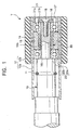
- FIG. 1 shows an example of a top roller T.
- This top roller T differs from the conventional ones in that a spacer 14 corresponding only to a conventional outer circumferential spacer is installed between an inner bearing 20 and an outer bearing 21 while a pre-loading spring 30 is installed on the inner circumferential side.
- the pre-loading spring 30 applies an elastic force to press an inner ring 20b of the bearing 20 against a pressure receiving section 10b of the shaft 10 while pressing an inner ring 21b of the bearing 21 against a washer 16.
- the inner rings 20b and 21b of the bearings 20 and 21 can rotate integrally with the shaft 10.
- the pre-loading spring 30 is installed between the bearings 20 and 21, the top roller T can be assembled and disassembled easily, enabling the bearings to be simply replaced. Besides, when the roller cylinder 12 is installed, if it collides against the outer bearing 21, the pre-loading spring 30 acts as a buffer to prevent damage to the bearings.
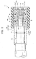
- Figure 2 shows 0-rings 31 and 32 comprising elastic bodies and installed between the spacer 14 and the outer rings 20a and 21a of the bearings 20 and 21 in such a way as to be slightly compressed.
- the 0-rings 31 and 32 fill the gap between the spacer 14 and the outer rings 20a and 21a of the bearings 20 and 21, thereby preventing the loosening of the roller cylinder 12 externally installed on the outer rings 20a and 21a and the spacer 14.
- This configuration prevents vibration despite the rotation of the roller cylinder 12 at a high speed, thereby enabling uniform drafting at a high speed.
- the elastic member installed between the inner rings 20b and 21b of the bearings 20 and 21 may comprise rubber instead of the spring.
- a configuration is possible in which 0-rings are disposed at both ends of the spacer.
- both the inner and outer rings of the bearings can be prevented from loosening.
- uniform drafting can be executed at a high speed.
Landscapes
- Engineering & Computer Science (AREA)
- Mechanical Engineering (AREA)
- Textile Engineering (AREA)
- Spinning Or Twisting Of Yarns (AREA)
Claims (8)
- Oberwalze für ein Streckwerk zum Strecken eines Faserbündels, wobei die Oberwalze (T)
eine Welle (10),
auf der Welle (10) angeordnete Lager (20, 21),
einen Walzenzylinder (12), der über die Lager (20, 21) drehbar auf der Welle (10) angebracht ist, und
ein elastisches Element (30) umfaßt, das zwischen den Lagern (20, 21) angeordnet ist,
dadurch gekennzeichnet, daß
jedes der Lager (20, 21) einen Außenring und einen Innenring (20a, 20b, 21a, 21b) umfaßt,
wobei der Innenring (20b, 21b) eines der Lager (20, 21) an einer radial vorstehenden Druckaufnahmefläche angreift, die an einem Ende der Welle (10) vorgesehen ist, und
das elastische Element (30) zwischen den Innenringen (20b, 21b) der Lager (20, 21) in solcher Weise angeordnet ist, daß auf die Lager (20, 21) eine Axiallast ausgeübt wird, wobei das elastische Element das Bestreben hat, die Lager (20, 21) in entgegengesetzte Axialrichtungen zu schieben. - Oberwalze für ein Streckwerk nach Anspruch 1, dadurch gekennzeichnet, daß das elastische Element eine Feder (30) ist.
- Oberwalze für ein Streckwerk nach Anspruch 1, dadurch gekennzeichnet, daß das elastische Element Gummi umfaßt.
- Oberwalze für ein Streckwerk nach einem der vorhergehenden Ansprüche, dadurch gekennzeichnet, daß ein separater axialer Abstandhalter (14) zwischen den Außenringen (20a, 21a) der Lager (20, 21) angeordnet ist.
- Oberwalze für ein Streckwerk nach einem der vorhergehenden Ansprüche, dadurch gekennzeichnet, daß die Außenringe (20a, 21a) der Lager (20, 21) mit einem Axialdruck beaufschlagt sind, um ein Lockerwerden von ihr zu verhindern.
- Oberwalze für ein Streckwerk nach Anspruch 5, dadurch gekennzeichnet, daß ein O-Ring (31, 32) vorgesehen ist, um die Außenringe (20a, 21a) der Lager (20, 21) mit einem Axialdruck zu beaufschlagen, um ein Lockerwerden von ihr zu verhindern.
- Oberwalze für ein Streckwerk nach Anspruch 4 und zusätzlich nach Anspruch 5 oder 6, dadurch gekennzeichnet, daß an beiden axialen Enden des Abstandhalters (14) der Außenringe (20a, 21a) O-Ringe (31, 32) so angeordnet sind, daß sie zwischen den axialen Enden des Abstandhalters (14) der Außenringe (20a, 21a) und den Außenringen (20a, 21a) der Lager (20, 21) deformiert werden.
- Oberwalze für ein Streckwerk nach einem der Ansprüche 4 bis 7, dadurch gekennzeichnet, daß der separate, zwischen den Außenringen (20a, 21 a) der Lager (20, 21) vorgesehene axiale Abstandhalter (14) eine axiale Länge hat, die kleiner als der axiale Abstand zwischen den Innenringen (20b, 21b) ist.
Applications Claiming Priority (2)
| Application Number | Priority Date | Filing Date | Title |
|---|---|---|---|
| JP10053133A JP3129276B2 (ja) | 1998-03-05 | 1998-03-05 | ドラフト装置のトップローラー |
| JP5313398 | 1998-03-05 |
Publications (3)
| Publication Number | Publication Date |
|---|---|
| EP0940486A2 EP0940486A2 (de) | 1999-09-08 |
| EP0940486A3 EP0940486A3 (de) | 2000-10-04 |
| EP0940486B1 true EP0940486B1 (de) | 2003-10-01 |
Family
ID=12934330
Family Applications (1)
| Application Number | Title | Priority Date | Filing Date |
|---|---|---|---|
| EP99101776A Expired - Lifetime EP0940486B1 (de) | 1998-03-05 | 1999-02-12 | Oberwalze für ein Streckwerk |
Country Status (5)
| Country | Link |
|---|---|
| US (1) | US6032336A (de) |
| EP (1) | EP0940486B1 (de) |
| JP (1) | JP3129276B2 (de) |
| CN (1) | CN1272488C (de) |
| DE (1) | DE69911673T2 (de) |
Families Citing this family (9)
| Publication number | Priority date | Publication date | Assignee | Title |
|---|---|---|---|---|
| JP2001140869A (ja) * | 1999-11-19 | 2001-05-22 | Minebea Co Ltd | 複列軸受 |
| DE10347192B4 (de) * | 2003-10-10 | 2012-02-09 | TRüTZSCHLER GMBH & CO. KG | Vorrichtung an einer Strecke für Textilfaserbänder mit hintereinander angeordneten Walzenpaaren und einer Putzeinrichtung für jede Oberwalze |
| US6971802B2 (en) * | 2003-12-23 | 2005-12-06 | Vezina Martin J | Bearing preload cage assembly |
| CN1332085C (zh) * | 2004-07-22 | 2007-08-15 | 陈兆南 | 纺机双滚道上罗拉轴承装配工艺及其专用校正工具 |
| DE102007037514A1 (de) * | 2007-08-08 | 2009-02-12 | Schaeffler Kg | Andruckrolle für Textilmaschinen |
| JP2011117518A (ja) * | 2009-12-02 | 2011-06-16 | Tmt Machinery Inc | ローラユニット |
| CN102109015B (zh) * | 2009-12-24 | 2016-03-09 | 陈忠和 | 纺机外圈双沟槽上罗拉轴承装配工艺 |
| JP2015113551A (ja) | 2013-12-13 | 2015-06-22 | 村田機械株式会社 | ドラフトローラの内側筒体、ドラフトローラのローラ部、ドラフトローラ、ドラフト装置、及び空気紡績機 |
| JP6472375B2 (ja) | 2015-12-25 | 2019-02-20 | ミネベアミツミ株式会社 | モータ |
Family Cites Families (7)
| Publication number | Priority date | Publication date | Assignee | Title |
|---|---|---|---|---|
| CH181506A (de) * | 1933-01-02 | 1935-12-31 | Aeberli Arnold | Streckwerk zum Strecken von Textilfasern, für Selfaktoren, Ringspinn- und Streckmaschinen. |
| DE1871941U (de) * | 1962-02-20 | 1963-05-09 | Schurr Stahlecker & Grill | Lagerung von oberwalzen fuer streck- oder lieferwerke von spinnereimaschinen. |
| JPS5552091Y2 (de) * | 1976-04-30 | 1980-12-03 | ||
| DE3038112C2 (de) * | 1980-10-09 | 1982-09-30 | Skf Kugellagerfabriken Gmbh, 8720 Schweinfurt | Verfahren zum Einstellen der axialen Vorspannung einer zweireihigen Radialwälzlagerung für eine Welle und demgemäß montierte Lagerung |
| US4541742A (en) * | 1983-05-02 | 1985-09-17 | General Motors Corporation | Unitized steering column bearing assembly |
| US4852230A (en) * | 1988-04-04 | 1989-08-01 | The Buschman Company | Method of fabricating rollers for use in roller conveyor systems |
| US5308172A (en) * | 1993-07-19 | 1994-05-03 | General Electric Company | Bearing assembly |
-
1998
- 1998-03-05 JP JP10053133A patent/JP3129276B2/ja not_active Expired - Fee Related
-
1999
- 1999-02-08 US US09/246,159 patent/US6032336A/en not_active Expired - Lifetime
- 1999-02-12 DE DE69911673T patent/DE69911673T2/de not_active Expired - Lifetime
- 1999-02-12 EP EP99101776A patent/EP0940486B1/de not_active Expired - Lifetime
- 1999-03-04 CN CNB991027256A patent/CN1272488C/zh not_active Expired - Lifetime
Also Published As
| Publication number | Publication date |
|---|---|
| CN1232093A (zh) | 1999-10-20 |
| DE69911673D1 (de) | 2003-11-06 |
| JP3129276B2 (ja) | 2001-01-29 |
| EP0940486A3 (de) | 2000-10-04 |
| DE69911673T2 (de) | 2004-08-12 |
| JPH11247036A (ja) | 1999-09-14 |
| CN1272488C (zh) | 2006-08-30 |
| US6032336A (en) | 2000-03-07 |
| EP0940486A2 (de) | 1999-09-08 |
Similar Documents
| Publication | Publication Date | Title |
|---|---|---|
| EP0940486B1 (de) | Oberwalze für ein Streckwerk | |
| US3890854A (en) | Rolling bearing assembly, in particular for a steering shaft of an automobile vehicle | |
| KR101356150B1 (ko) | 롤러 조립체, 롤러 유닛 및 컨베이어 장치 | |
| EP0825429B1 (de) | Lagereinrichtung | |
| CN101501353B (zh) | 双列圆锥滚子轴承单元 | |
| JPH0118893Y2 (de) | ||
| CA1242237A (en) | Elastomeric bearing damper apparatus and associated methods | |
| US4408526A (en) | No-play gear drive for printing machines | |
| CN1305591C (zh) | 辊环的环形支撑装置 | |
| US5662950A (en) | Roll bending device for forming plastic sheet | |
| KR100278537B1 (ko) | 조심륜부착구름베어링 | |
| JP4172972B2 (ja) | 揺動軸受 | |
| CN112553721A (zh) | 用于纺织机械的罗拉皮辊装置 | |
| US4010527A (en) | Textile drafting roll assembly | |
| KR100310400B1 (ko) | 선형안내식이동유니트용지지베어링 | |
| FI83793B (fi) | Anordning foer faestande av slipsten vid traeslipmaskin pao en rotationsaxel. | |
| JP2008185063A (ja) | 複列円すいころ軸受ユニット | |
| JP2001113307A (ja) | 圧延ロールとその組立方法 | |
| EP1423623B1 (de) | Freilauf mit einem mit faserverstärktem kunststoff umwickelten freilaufaussenring | |
| KR200144521Y1 (ko) | 편심 베어링 분해용 지그 | |
| JP5050477B2 (ja) | 複列円すいころ軸受ユニット | |
| US7249396B2 (en) | Apparatus at a spinning preparation machine, especially a carding machine, opener, cleaner or the like | |
| EP4215654B1 (de) | Faserbandkondensationsvorrichtung für eine spinnmaschine | |
| US6237196B1 (en) | Top roller of a drafting apparatus | |
| US7086795B2 (en) | Roller assembly |
Legal Events
| Date | Code | Title | Description |
|---|---|---|---|
| PUAI | Public reference made under article 153(3) epc to a published international application that has entered the european phase |
Free format text: ORIGINAL CODE: 0009012 |
|
| AK | Designated contracting states |
Kind code of ref document: A2 Designated state(s): DE FR IT |
|
| AX | Request for extension of the european patent |
Free format text: AL;LT;LV;MK;RO;SI |
|
| PUAL | Search report despatched |
Free format text: ORIGINAL CODE: 0009013 |
|
| AK | Designated contracting states |
Kind code of ref document: A3 Designated state(s): AT BE CH CY DE DK ES FI FR GB GR IE IT LI LU MC NL PT SE |
|
| AX | Request for extension of the european patent |
Free format text: AL;LT;LV;MK;RO;SI |
|
| 17P | Request for examination filed |
Effective date: 20010213 |
|
| AKX | Designation fees paid |
Free format text: DE FR IT |
|
| 17Q | First examination report despatched |
Effective date: 20020926 |
|
| GRAH | Despatch of communication of intention to grant a patent |
Free format text: ORIGINAL CODE: EPIDOS IGRA |
|
| GRAS | Grant fee paid |
Free format text: ORIGINAL CODE: EPIDOSNIGR3 |
|
| GRAA | (expected) grant |
Free format text: ORIGINAL CODE: 0009210 |
|
| AK | Designated contracting states |
Kind code of ref document: B1 Designated state(s): DE FR IT |
|
| PG25 | Lapsed in a contracting state [announced via postgrant information from national office to epo] |
Ref country code: FR Free format text: LAPSE BECAUSE OF FAILURE TO SUBMIT A TRANSLATION OF THE DESCRIPTION OR TO PAY THE FEE WITHIN THE PRESCRIBED TIME-LIMIT Effective date: 20031001 |
|
| REF | Corresponds to: |
Ref document number: 69911673 Country of ref document: DE Date of ref document: 20031106 Kind code of ref document: P |
|
| PLBE | No opposition filed within time limit |
Free format text: ORIGINAL CODE: 0009261 |
|
| STAA | Information on the status of an ep patent application or granted ep patent |
Free format text: STATUS: NO OPPOSITION FILED WITHIN TIME LIMIT |
|
| 26N | No opposition filed |
Effective date: 20040702 |
|
| EN | Fr: translation not filed | ||
| PGFP | Annual fee paid to national office [announced via postgrant information from national office to epo] |
Ref country code: IT Payment date: 20120224 Year of fee payment: 14 |
|
| PG25 | Lapsed in a contracting state [announced via postgrant information from national office to epo] |
Ref country code: IT Free format text: LAPSE BECAUSE OF NON-PAYMENT OF DUE FEES Effective date: 20130212 |
|
| PGFP | Annual fee paid to national office [announced via postgrant information from national office to epo] |
Ref country code: DE Payment date: 20180219 Year of fee payment: 20 |
|
| REG | Reference to a national code |
Ref country code: DE Ref legal event code: R071 Ref document number: 69911673 Country of ref document: DE |