EP0940134B1 - Dispositif élévateur pour personnes avec système de sécurité contre un déroulememt inadmissible d'un élément de sangle - Google Patents
Dispositif élévateur pour personnes avec système de sécurité contre un déroulememt inadmissible d'un élément de sangle Download PDFInfo
- Publication number
- EP0940134B1 EP0940134B1 EP99103758A EP99103758A EP0940134B1 EP 0940134 B1 EP0940134 B1 EP 0940134B1 EP 99103758 A EP99103758 A EP 99103758A EP 99103758 A EP99103758 A EP 99103758A EP 0940134 B1 EP0940134 B1 EP 0940134B1
- Authority
- EP
- European Patent Office
- Prior art keywords
- lift
- latching element
- shaft
- gear
- gear wheel
- Prior art date
- Legal status (The legal status is an assumption and is not a legal conclusion. Google has not performed a legal analysis and makes no representation as to the accuracy of the status listed.)
- Expired - Lifetime
Links
Images
Classifications
-
- A—HUMAN NECESSITIES
- A62—LIFE-SAVING; FIRE-FIGHTING
- A62B—DEVICES, APPARATUS OR METHODS FOR LIFE-SAVING
- A62B35/00—Safety belts or body harnesses; Similar equipment for limiting displacement of the human body, especially in case of sudden changes of motion
- A62B35/0093—Fall arrest reel devices
-
- F—MECHANICAL ENGINEERING; LIGHTING; HEATING; WEAPONS; BLASTING
- F16—ENGINEERING ELEMENTS AND UNITS; GENERAL MEASURES FOR PRODUCING AND MAINTAINING EFFECTIVE FUNCTIONING OF MACHINES OR INSTALLATIONS; THERMAL INSULATION IN GENERAL
- F16D—COUPLINGS FOR TRANSMITTING ROTATION; CLUTCHES; BRAKES
- F16D41/00—Freewheels or freewheel clutches
- F16D41/12—Freewheels or freewheel clutches with hinged pawl co-operating with teeth, cogs, or the like
-
- A—HUMAN NECESSITIES
- A61—MEDICAL OR VETERINARY SCIENCE; HYGIENE
- A61G—TRANSPORT, PERSONAL CONVEYANCES OR ACCOMMODATION SPECIALLY ADAPTED FOR PATIENTS OR DISABLED PERSONS; OPERATING TABLES OR CHAIRS; CHAIRS FOR DENTISTRY; FUNERAL DEVICES
- A61G7/00—Beds specially adapted for nursing; Devices for lifting patients or disabled persons
- A61G7/10—Devices for lifting patients or disabled persons, e.g. special adaptations of hoists thereto
- A61G7/104—Devices carried or supported by
- A61G7/1042—Rail systems
Definitions
- the invention relates to a person lifter such as a ceiling lifter or floor lifter Holder for transporting a person with a particular disability, comprising a belt element, that starts from a shaft for winding and unwinding and over which the holder can be raised and lowered, the shaft being connected to a first gear, as well as securing against unauthorized rolling of the belt element.
- a lifter be it Ceiling lifts, be it floor lifts - can be transported.
- a belt goes from the lifter from the z.
- a seat such as a seat cloth is connected to accommodate the person.
- the corresponding belts are unrolled from a shaft by means of electric motors this rolled up.
- the output shaft of an electric motor is one with a gear combing shaft, which in turn drives the shaft via a transmission gear. If the output shaft of the meshing wheel, for example, by wear of teeth no longer ensures the required positive or non-positive connection, there is a risk that when the person is lifted, it drops at an impermissible speed, so that the risk of injury increases.
- a load securing device for a crane system is known from DE 40 00 831 A1.
- To inadmissible Sinking speed of a support element to prevent further lowering is a load hook or a load bottle connected to a safety suspension device, which via a Chain pocket wheel is guided.
- a catch block runs along one side of the chain pocket wheel, between the and the chain pocket wheel a wedge can then be inserted when the Sink rate exceeds an impermissible value.
- the present invention is based on the problem of a personal hoist at the beginning to further develop the type mentioned in such a way that it is ensured with structurally simple measures is that if the belt unrolled at an unacceptable speed, the shaft would lock takes place so that there is no danger to a person to be transported.
- the problem is solved in that the first gearwheel with a second Gear meshes and that a locking element in the first and the second gear Area whose engagement is assigned such that the locking element between the first and the second gear can be pushed at an impermissible rate of descent of the holder.
- the locking element is preferably wedge-shaped on the gear wheel side and with it When force is applied, the tip can be pushed between the meshing gears.
- the Locking element connected to an armature of a magnet or be movable by it.
- the magnet itself is dependent on the speed of rotation of the shaft or whose speed can be activated to move the locking element.
- the speed of the shaft itself can be measured using a pulse counter to then activate the magnet.
- the blocking element which is preferably wedge-shaped on the tip side, at least on one is structured with one of the gears interacting side. This is preferred selected a geometry that corresponds to that of the meshing gear.
- the locking element between the meshing gears moved at the moment when the shaft receiving the belt element is inadmissible has high rotational speed, which otherwise lead to a lowering of a seat would what could endanger a person. It is with the combing Interlocking element interacting with gears, so to speak, drawn in between the gears, whereby an automatic blocking of the gears and thus a standstill of the Wave occurs.
- Known ceiling or floor lifts for transporting people have one Not shown shaft can be wound up or unwound from this belt, from which again a seat or a seat belt for the person runs out.
- a bracket or a housing can be raised or lowered from which the seat or Seat belt runs out.
- the shaft itself is powered by an electric motor, preferably a battery Electric motor, rotated, being between the output shaft of the motor and the Shaft even gearboxes are available.
- the shaft is with a gear connected, which meshes directly with another gear, which in turn for Example interacts with the drive shaft of the electric motor.
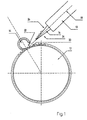
- Solenoid actuated locking element 10 is provided, which then between two meshing gears 12, 14 is displaceable if that directly connected to the shaft Gear, in the exemplary embodiment the gear 12, an impermissibly high rotational speed has, which are determined for example by means of a pulse counter can.
- the gear 14 itself can directly or indirectly with the output shaft Electric motor be connected.
- the gear connected to the shaft 12 can also be driven by another gear.
- the locking element 10 has a tapered front end 16, which is in the effective range between the teeth 12, 14 along the straight line 18 when due to an impermissibly high rotational speed, the magnet is activated and thus the locking element 10 is adjusted in the direction of the gears 12, 14.
- Through the wedge-shaped trained tip 16 is the locking element when gripping the teeth 20, 22 of the Gears 12, 14 drawn between them, causing the gears to be non-rotatable 12.1 4 is caused with the result that the shaft emerging from the gear 12 came to a standstill.
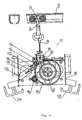
- a person ceiling lift 70 is shown in the detail, by means of which a disabled person Moving person from one place to another and lowering or lifting can.
- a carrier 72 runs along a ceiling on a ceiling (not shown) preferably a battery-powered rotor 74 can be moved.
- Runner 74 has one Hook 76 on, in which a loop 78 of a belt 80 can be hung, which in turn on a Shaft 82 or roll up or unwindable from this.
- the shaft 82 is connected to a Gear 84 connected, which is rotated via a drive pinion 86, so to wind the belt 80 on the shaft 82 or to let it off.
- the pinion 86 is driven by an electric motor, preferably a battery-operated motor Offset rotary movement.
- the aforementioned elements are arranged in a housing 88, of which mounts or fastenings 106, 108 go out, in which straps or seats can be hooked in the usual manner are to accommodate people.
- the belt 80 passes through the housing 88 via an opening which has a slack rope safety device 90 is assigned according to the teaching of DE 91 10 218 U1. This checks whether the belt 80 is tensioned to the extent necessary. If this is not the case, use the Slack rope protection 90 the drive and thus a rotation of the pinion 86 interrupted.
- a pinion 82 which meshes with the reference number also meshes with the gear 84 14 provided pinion according to FIG. 1 corresponds.
- a pulse counter 94 which acts as a light barrier can be formed, the rotational speed of the pinion 92 is monitored. If, according to the embodiment of FIG. 1, the pulse number is too high and thus Rotation speed of the pinion 92 is determined, a signal for an electromagnet 96 triggered, so that its plunger 98 with its front as a locking element formed end 102 or a corresponding element connected to the plunger in the area between the meshing gears 84, 92 passes, causing the locking element 102 is pulled between the gears 84, 92 with the result that further turning this is omitted.
- the electromagnet 96 is fixed on a mounting plate 104. It can also be seen that the Tappet 98 is surrounded by a coil spring 100 which is attached to the housing of the magnet 96 is supported. Thus, the blocking element 102, ie. H. the Tip, only be moved into the area between the gears 84, 92 when the Magnet 96 is excited to the extent necessary.
- a control board is also arranged, via which u. a. a Evaluation of the signals of the pulse counter 94 and thus activation of the magnet 96 takes place and the drive for the shaft 82 is controlled.
Landscapes
- Engineering & Computer Science (AREA)
- General Engineering & Computer Science (AREA)
- Mechanical Engineering (AREA)
- Emergency Management (AREA)
- Business, Economics & Management (AREA)
- General Health & Medical Sciences (AREA)
- Health & Medical Sciences (AREA)
- Automotive Seat Belt Assembly (AREA)
- Gear Transmission (AREA)
- Emergency Lowering Means (AREA)
- Vessels, Lead-In Wires, Accessory Apparatuses For Cathode-Ray Tubes (AREA)
- Portable Nailing Machines And Staplers (AREA)
- Transmission Devices (AREA)
Claims (6)
- Lève-personne, tel qu'un lève-personne sur rail au plafond ou un lève-personne mobile au sol, avec support pour le transport d'une personne en particulier handicapée, comprenant une sangle (80) partant d'un arbre de rotation pour l'enroulement ou le déroulement grâce à laquelle le support peut être élevé ou descendu, sachant que l'arbre de rotation est relié à une première roue dentée (12, 84) tout comme l'est une sécurité contre un déroulement non désiré de la sangle,
caractérisé en ce que
la première roue dentée (12, 84) s'engrène dans une deuxième roue dentée (14, 92) et qu'un élément de blocage (10, 102) est conjugué à la première et à la deuxième roue dentée au niveau de leur engrenage de manière que l'élément de blocage peut être poussé entre la première et la deuxième roue dentée en cas de vitesse d'abaissement excessive du support. - Lève-personne selon la revendication 1,
caractérisé en ce que
l'élément de blocage (10, 102) est conçu de manière cunéiforme au moins du côté des roues dentées et peut, au moyen d'une force, être poussé avec son extrémité entre les deux roues dentées s'engrenant (12, 14, 84, 92). - Lève-personne selon au moins la revendication 1,
caractérisé en ce que
l'élément de blocage (10, 102) est relié au noyau (98) d'un aimant (96) ou plus précisément peut être mis en mouvement par celui-ci et que l'aimant est activé, pour la poussée de l'élément de blocage, en particulier en fonction de la vitesse de rotation de l'arbre (82) ou de son nombre de tours, sachant que le nombre de tours de l'arbre peut être en particulier mesuré au moyen d'un compteur d'impulsions. - Lève-personne selon au moins la revendication 1,
caractérisé en ce que
l'élément de blocage (10) est structuré au moins sur une face en interaction avec une des roues dentées (12, 14) qui présente de préférence une géométrie correspondant à celle de la roue dentée (12, 14) en interaction avec la face structurée (24, 26) de l'élément de blocage (14). - Lève-personne selon au moins la revendication 1,
caractérisé en ce que
l'élément de blocage (10, 102) peut être poussé entre les deux roues dentées s'engrenant (12, 14, 84, 92) afin de les bloquer. - Lève-personne selon au moins la revendication 1,
caractérisé en ce que
l'élément de blocage (10) peut être poussé entre les roues dentées (12, 14, 84, 92) le long d'une droite (18) qui coupe perpendiculairement une droite reliant les axes des roues dentées.
Applications Claiming Priority (2)
| Application Number | Priority Date | Filing Date | Title |
|---|---|---|---|
| DE29803558U DE29803558U1 (de) | 1998-03-02 | 1998-03-02 | Sicherung gegen ein unzulässiges Abrollen eines Gurtelementes |
| DE29803558U | 1998-03-02 |
Publications (3)
| Publication Number | Publication Date |
|---|---|
| EP0940134A2 EP0940134A2 (fr) | 1999-09-08 |
| EP0940134A3 EP0940134A3 (fr) | 2001-05-30 |
| EP0940134B1 true EP0940134B1 (fr) | 2004-07-07 |
Family
ID=8053387
Family Applications (1)
| Application Number | Title | Priority Date | Filing Date |
|---|---|---|---|
| EP99103758A Expired - Lifetime EP0940134B1 (fr) | 1998-03-02 | 1999-02-26 | Dispositif élévateur pour personnes avec système de sécurité contre un déroulememt inadmissible d'un élément de sangle |
Country Status (3)
| Country | Link |
|---|---|
| US (1) | US6129302A (fr) |
| EP (1) | EP0940134B1 (fr) |
| DE (2) | DE29803558U1 (fr) |
Cited By (2)
| Publication number | Priority date | Publication date | Assignee | Title |
|---|---|---|---|---|
| US11376180B2 (en) | 2016-12-01 | 2022-07-05 | Liko Research & Development Ab | Gates for overhead lifting rails |
| US11793702B2 (en) | 2018-10-12 | 2023-10-24 | Liko Research & Development Ab | Gates with transition ramps for overhead lifting rails |
Families Citing this family (3)
| Publication number | Priority date | Publication date | Assignee | Title |
|---|---|---|---|---|
| GB2451835B (en) * | 2007-08-13 | 2009-07-01 | Checkmate Safety Llp | Fall arrest block |
| DE102012202257B4 (de) | 2012-02-15 | 2014-10-30 | ebm-papst ZEITLAUF GmbH & Co. KG | Hebevorrichtung, insbesondere Patientenlifter, mit Abrollsicherung |
| FR3120541B1 (fr) * | 2021-03-10 | 2023-03-17 | Zedel | Longe à longueur modulable, harnais d’encordement, dispositif de remontée sur corde et procédé d’utilisation |
Family Cites Families (7)
| Publication number | Priority date | Publication date | Assignee | Title |
|---|---|---|---|---|
| DE7424538U (de) | 1974-11-14 | Kauffmann T Kg | Geschwindigkeitsabhängig auslösende Fangvorrichtung für heb- und senkbare Lasten | |
| DE894354C (de) | 1938-04-02 | 1953-10-22 | Joseph Trouin | Vorrichtung zum Schutz gegen Abstuerzen |
| CH362795A (de) * | 1958-10-01 | 1962-06-30 | Koller Josef | Patientenhebeeinrichtung |
| DE3802775C1 (en) | 1988-01-30 | 1989-09-21 | Wilhelm 4420 Coesfeld De Uhlenkotte | Securing device for a winding shaft |
| DE4000831A1 (de) * | 1990-01-13 | 1991-07-18 | Harald Baecker | Lastsicherung fuer eine krananlage |
| DE9110218U1 (de) | 1991-08-19 | 1992-01-02 | Horcher, Willi, 61137 Schöneck | Lastträger |
| DE9418949U1 (de) | 1994-11-28 | 1995-03-30 | Horcher, Stefan, 61137 Schöneck | Personen-Hebegerät |
-
1998
- 1998-03-02 DE DE29803558U patent/DE29803558U1/de not_active Expired - Lifetime
-
1999
- 1999-02-26 EP EP99103758A patent/EP0940134B1/fr not_active Expired - Lifetime
- 1999-02-26 DE DE59909874T patent/DE59909874D1/de not_active Expired - Fee Related
- 1999-03-02 US US09/260,072 patent/US6129302A/en not_active Expired - Fee Related
Cited By (2)
| Publication number | Priority date | Publication date | Assignee | Title |
|---|---|---|---|---|
| US11376180B2 (en) | 2016-12-01 | 2022-07-05 | Liko Research & Development Ab | Gates for overhead lifting rails |
| US11793702B2 (en) | 2018-10-12 | 2023-10-24 | Liko Research & Development Ab | Gates with transition ramps for overhead lifting rails |
Also Published As
| Publication number | Publication date |
|---|---|
| EP0940134A2 (fr) | 1999-09-08 |
| DE29803558U1 (de) | 1998-06-25 |
| US6129302A (en) | 2000-10-10 |
| EP0940134A3 (fr) | 2001-05-30 |
| DE59909874D1 (de) | 2004-08-12 |
Similar Documents
| Publication | Publication Date | Title |
|---|---|---|
| EP1219510B1 (fr) | Limiteur de force dans un enrouleur de ceinture de sécurité | |
| EP2625131B1 (fr) | Engin de levage à courroie dentée | |
| DE3320942C2 (de) | Rückholvorrichtung mit Zugentlastung für einen Sicherheitsgurt | |
| EP1981800A2 (fr) | Plate-forme de stationnement pour des vehicules a moteur | |
| EP0712803A1 (fr) | Système d'évacuation pour ascenseurs | |
| EP2459827B1 (fr) | Dispositif d'entraînement de portail, avec dispositif de surveillance des moyens de traction, ainsi que portail qui en est équipé | |
| EP0231227B1 (fr) | Dispositif d'accouplement pour l'arbre enrouleur d'une ceinture de securite a inertie avec dispositif de retenue | |
| DE2504576A1 (de) | Automatisch blockierende rueckziehvorrichtung fuer sicherheitsgurtband o.dgl. | |
| EP1965018A2 (fr) | Porte dotée d'un équilibrage du ressort de traction et dispositif d'entraînement correspondant | |
| DE3132073A1 (de) | "elektromotorisch angetriebener rafflamellenstore mit notantrieb" | |
| DE3432043C2 (fr) | ||
| DE102012202257B4 (de) | Hebevorrichtung, insbesondere Patientenlifter, mit Abrollsicherung | |
| DE19907632C2 (de) | Bodengleiche Abdeckung für eine Wartungsöffnung, insbesondere für einen Maschinenraum an einer Personenförderanlage | |
| EP1566358A1 (fr) | Ascenseur à poulie de traction sans machinerie | |
| EP0940134A2 (fr) | Système de sécurité contre une déroulememt inadmissible d'un élément de sangle | |
| DE102013215901A1 (de) | Servicelift | |
| DE3332957A1 (de) | Automatische tuer, insbesondere als zugangstuer zu einer verkaufsflaeche | |
| DE102004022134A1 (de) | Gurtaufroller für einen Fahrzeugsicherheitsgurt | |
| EP2565360B1 (fr) | Dispositif de fixation d'un store sur un cylindre d'enroulement | |
| DE4000831A1 (de) | Lastsicherung fuer eine krananlage | |
| DE10216342C1 (de) | Sonnenschutzanlage mit Notraffvorrichtung | |
| DE4126402C2 (de) | Lastträger | |
| DE102012200035B4 (de) | Antriebsvorrichtung zum Auf- und Abwickeln einer Verdunkelungsvorrichtung, insbesondere eines Rollladens o.dgl. | |
| DE3421838A1 (de) | Sicherheitsgurteinzugsautomat | |
| DE202005006255U1 (de) | Kraftbeätigtes Tor sowie dafür verwendbarer Torantrieb |
Legal Events
| Date | Code | Title | Description |
|---|---|---|---|
| PUAI | Public reference made under article 153(3) epc to a published international application that has entered the european phase |
Free format text: ORIGINAL CODE: 0009012 |
|
| AK | Designated contracting states |
Kind code of ref document: A2 Designated state(s): DE GB NL |
|
| AX | Request for extension of the european patent |
Free format text: AL;LT;LV;MK;RO;SI |
|
| PUAL | Search report despatched |
Free format text: ORIGINAL CODE: 0009013 |
|
| AK | Designated contracting states |
Kind code of ref document: A3 Designated state(s): AT BE CH CY DE DK ES FI FR GB GR IE IT LI LU MC NL PT SE |
|
| AX | Request for extension of the european patent |
Free format text: AL;LT;LV;MK;RO;SI |
|
| 17P | Request for examination filed |
Effective date: 20010719 |
|
| AKX | Designation fees paid |
Free format text: DE GB NL |
|
| 17Q | First examination report despatched |
Effective date: 20030506 |
|
| GRAP | Despatch of communication of intention to grant a patent |
Free format text: ORIGINAL CODE: EPIDOSNIGR1 |
|
| RTI1 | Title (correction) |
Free format text: LIFT FOR PERSONS WITH SECURITY DEVICE AGAINST AN INADMISSIBLE UNROLLING OF A BELTELEMENT |
|
| RTI1 | Title (correction) |
Free format text: LIFT FOR PERSONS WITH SECURITY DEVICE AGAINST AN INADMISSIBLE UNROLLING OF A BELT ELEMENT |
|
| GRAS | Grant fee paid |
Free format text: ORIGINAL CODE: EPIDOSNIGR3 |
|
| GRAA | (expected) grant |
Free format text: ORIGINAL CODE: 0009210 |
|
| AK | Designated contracting states |
Kind code of ref document: B1 Designated state(s): DE GB NL |
|
| REG | Reference to a national code |
Ref country code: GB Ref legal event code: FG4D Free format text: NOT ENGLISH |
|
| REF | Corresponds to: |
Ref document number: 59909874 Country of ref document: DE Date of ref document: 20040812 Kind code of ref document: P |
|
| GBT | Gb: translation of ep patent filed (gb section 77(6)(a)/1977) |
Effective date: 20041020 |
|
| PLBE | No opposition filed within time limit |
Free format text: ORIGINAL CODE: 0009261 |
|
| STAA | Information on the status of an ep patent application or granted ep patent |
Free format text: STATUS: NO OPPOSITION FILED WITHIN TIME LIMIT |
|
| 26N | No opposition filed |
Effective date: 20050408 |
|
| PGFP | Annual fee paid to national office [announced via postgrant information from national office to epo] |
Ref country code: GB Payment date: 20070126 Year of fee payment: 9 |
|
| PGFP | Annual fee paid to national office [announced via postgrant information from national office to epo] |
Ref country code: NL Payment date: 20070214 Year of fee payment: 9 |
|
| PGFP | Annual fee paid to national office [announced via postgrant information from national office to epo] |
Ref country code: DE Payment date: 20070226 Year of fee payment: 9 |
|
| GBPC | Gb: european patent ceased through non-payment of renewal fee |
Effective date: 20080226 |
|
| NLV4 | Nl: lapsed or anulled due to non-payment of the annual fee |
Effective date: 20080901 |
|
| PG25 | Lapsed in a contracting state [announced via postgrant information from national office to epo] |
Ref country code: NL Free format text: LAPSE BECAUSE OF NON-PAYMENT OF DUE FEES Effective date: 20080901 |
|
| PG25 | Lapsed in a contracting state [announced via postgrant information from national office to epo] |
Ref country code: DE Free format text: LAPSE BECAUSE OF NON-PAYMENT OF DUE FEES Effective date: 20080902 |
|
| PG25 | Lapsed in a contracting state [announced via postgrant information from national office to epo] |
Ref country code: GB Free format text: LAPSE BECAUSE OF NON-PAYMENT OF DUE FEES Effective date: 20080226 |