EP0938997A2 - Siège rabattable et inclinable pour véhicule - Google Patents
Siège rabattable et inclinable pour véhicule Download PDFInfo
- Publication number
- EP0938997A2 EP0938997A2 EP99103290A EP99103290A EP0938997A2 EP 0938997 A2 EP0938997 A2 EP 0938997A2 EP 99103290 A EP99103290 A EP 99103290A EP 99103290 A EP99103290 A EP 99103290A EP 0938997 A2 EP0938997 A2 EP 0938997A2
- Authority
- EP
- European Patent Office
- Prior art keywords
- seat
- seatback
- lever
- reclining
- pivotal
- Prior art date
- Legal status (The legal status is an assumption and is not a legal conclusion. Google has not performed a legal analysis and makes no representation as to the accuracy of the status listed.)
- Granted
Links
Images


Classifications
-
- B—PERFORMING OPERATIONS; TRANSPORTING
- B60—VEHICLES IN GENERAL
- B60N—SEATS SPECIALLY ADAPTED FOR VEHICLES; VEHICLE PASSENGER ACCOMMODATION NOT OTHERWISE PROVIDED FOR
- B60N2/00—Seats specially adapted for vehicles; Arrangement or mounting of seats in vehicles
- B60N2/02—Seats specially adapted for vehicles; Arrangement or mounting of seats in vehicles the seat or part thereof being movable, e.g. adjustable
- B60N2/20—Seats specially adapted for vehicles; Arrangement or mounting of seats in vehicles the seat or part thereof being movable, e.g. adjustable the back-rest being tiltable, e.g. to permit easy access
-
- B—PERFORMING OPERATIONS; TRANSPORTING
- B60—VEHICLES IN GENERAL
- B60N—SEATS SPECIALLY ADAPTED FOR VEHICLES; VEHICLE PASSENGER ACCOMMODATION NOT OTHERWISE PROVIDED FOR
- B60N2/00—Seats specially adapted for vehicles; Arrangement or mounting of seats in vehicles
- B60N2/02—Seats specially adapted for vehicles; Arrangement or mounting of seats in vehicles the seat or part thereof being movable, e.g. adjustable
- B60N2/22—Seats specially adapted for vehicles; Arrangement or mounting of seats in vehicles the seat or part thereof being movable, e.g. adjustable the back-rest being adjustable
- B60N2/235—Seats specially adapted for vehicles; Arrangement or mounting of seats in vehicles the seat or part thereof being movable, e.g. adjustable the back-rest being adjustable by gear-pawl type mechanisms
- B60N2/2352—Seats specially adapted for vehicles; Arrangement or mounting of seats in vehicles the seat or part thereof being movable, e.g. adjustable the back-rest being adjustable by gear-pawl type mechanisms with external pawls
- B60N2/2354—Seats specially adapted for vehicles; Arrangement or mounting of seats in vehicles the seat or part thereof being movable, e.g. adjustable the back-rest being adjustable by gear-pawl type mechanisms with external pawls and provided with memory locks
Definitions
- the present invention relates in general to vehicular seats and more particularly to the vehicular seats of a foldable reclining type. More specifically, the present invention relates to the foldable reclining seats for vehicles, which are commonly used as rear seats in a ban-type and/or one-box type motor vehicle.
- foldable seats are commonly used as rear seats for providing the rear part of the vehicle cabin with a larger luggage space when loading of a larger amount of luggage is needed by the vehicle. That is, when a seatback of the rear seat, which is arranged to face forward, is folded onto a seat proper, the luggage space is increased by a degree corresponding to the area possessed by the back of the folded seatback.
- Some of the foldable seats are of a reclining type which can provide the seatback with a desired angular position for comfortable sitting of a seat occupant.
- a foldable reclining seat of a vehicle which can be easily and safely handled by a seat occupant.
- a foldable reclining seat adapted to be mounted on a floor.
- the seat comprises a seat proper adapted to be mounted on the floor; a seatback arranged at a rear portion of the seat proper and pivotal about a given axis; biasing means for biasing the seatback to pivot in a folding direction relative to the seat proper; a reclining mechanism arranged at one side of the seat, the reclining mechanism enabling the seatback to take a desired angular position within a given range relative to the seat proper, the reclining mechanism assuming a locked condition wherein the seatback at the desired angular position is locked relative to the seat proper and an unlocked condition wherein the seatback is permitted to pivot in the folding direction due to the force of the biasing means; a stopper mechanism arranged at the other side of the seat, the stopper mechanism assuming a first condition wherein the seatback is permitted to pivot within a range corresponding to the given range and a second condition wherein the seatback is permitted to pivot in the folding direction to such
- Fig. 1 there is shown the foldable reclining seat according to the present invention, which seat is adapted to be used as a rear seat in ban-type and/or one-box type motor vehicles.
- the foldable reclining seat comprises generally a seat proper 9, a seatback 4, a reclining mechanism 50 and a stopper mechanism 51. That is, as will be described in detail hereinafter, the seatback 4 is pivotally arranged at a rear side of the seat proper 9 through the reclining mechanism 50 and the stopper mechanism 51.
- a front portion of the seat proper 9 is pivotally supported on a vehicular floor VF through two pivotal support units "PSa" and "PSb".
- Each pivotal support unit includes a bracket 13 which is secured to the vehicle floor VF and a link 10 which has a lower end pivotally connected through a pin 14 to the bracket 13 and an upper end pivotally connected through a pin 11 to a front side portion of the seat proper 9.
- a rear portion of the seat proper 9 is pivotally supported on the vehicle floor VF through both the reclining mechanism 50 and the stopper mechanism 51 in such a manner as will become apparent as the description proceeds.
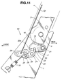
- the reclining mechanism 50 comprises a base plate 1 which is mounted on the vehicle floor "VF".
- An arm 3 is pivotally connected to the base plate 1 through a left center shaft 2.
- the arm 3 is secured to a lower left side of the seatback 4 by means of bolts 5.
- a curved follower link 7a is secured at its lower portion to a rear left side of the seat proper 9 through bolts 8 and pivotally connected at its upper end to the arm 3 through a pivot pin 6.
- the arm 3 is formed at its lower end with a semi-rounded portion 18.
- the periphery of the semi-rounded portion 18 is concentric with the left center shaft 2 and has a toothed portion 17 therearound.
- a tooth member 20 is pivotally connected through a pivot shaft 21 to the base plate 1, which has a toothed portion 19 selectively engageable with the toothed portion 17 of the arm 3.
- the tooth member 20 is formed at its free lower end with both a guide edge 20a and a recess 22.
- a cam 23 is pivotally connected through a pivot shaft 24 to the base plate 1, which is selectively engageable with the free lower end (viz., the guide edge 20a and the recess 22) of the tooth member 20.
- the cam 23 is provided with a pin 25 which is movably put in an elongate slot 26 formed in a lever 27.
- the lever 27 is pivotally connected through a shaft 28 to the base plate 1.
- the lever 27 is biased in a clockwise direction about the shaft 28 by means of a spring 30.
- Pivotally connected to the lever 27 is an actuating rod 52 which leads to an after-mentioned lever unit 53 (see Fig. 1).
- a triangular plate member is spacedly mounted on the base plate 1 to rotatably support one ends of the center shaft 2 and the pivot shafts 21 and 24.
- the seatback 4 is constantly biased to pivot forwardly (viz., leftward in Fig. 11) about an axis of the left center shaft 2.
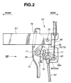
- the lever unit 53 is seen, which is installed on a front left edge of the seatback 4.
- the lever unit 53 generally comprises a first pivotal lever 54 to which the above-mentioned actuating rod 52 from the lever 27 is pivotally connected, a second pivotal lever 55 to which an after-mentioned actuating wire 58 is pivotally connected and a third pivotal lever 56 to which a pull tab 57 is pivotally connected.
- These first, second and third pivotal levers 54, 55 and 56 are pivotally connected to the seatback 4 (more specifically, a bracket 70 secured to a frame of the seatback 4) through a common pivot shaft 71 in an after-mentioned manner.
- the actuating wire 58 extends upward in the seatback 4 to a control knob 60 which is vertically slidably received in a recess 59 formed in an upper part of the seatback 4.
- Another actuating wire 61 extends downward from the control knob 60 toward the stopper mechanism 51.
- the lever unit 53 is mounted on a bracket 70 secured to the frame of the seatback 4.
- the above-mentioned first, second and third pivotal levers 54, 55 and 56 are pivotally connected through the common pivot shaft 71 to the bracket 70.
- the first pivotal lever 54 is interposed between the second and third pivotal levers 55 and 56, and as is seen from Fig. 1, among these levers 54, 55 and 56, the third pivotal lever 56 is positioned at the outermost left side.
- the first pivotal lever 54 is equipped with a control pin 72 which has one end 72a slidably received in an arcuate slot 73 formed in the second pivotal lever 55 and the other end 72b slidably received in an arcuate slot 74 formed in the third pivotal lever 56.
- the first pivotal lever 54 has a U-shaped free end 54a to which an upper bent end 52a of the actuating rod 52 is pivotally connected.
- a lower bend end 58a of the actuating wire 58 is pivotally connected to a free end of the second pivotal lever 55, and a rear end of the pull tab 57 is pivotally connected through a pin 75 to a free end of the third pivotal lever 56.
- the pull tab 57 passes through an opening 76 formed in the bracket 70.
- the respective arcuate slots 73 and 74 formed in the second and third pivotal levers 55 and 56 are coaxial with the common pivot shaft 71 and have the same length.
- both the second and third pivotal levers 55 and 56 are biased to pivot in a clockwise direction in Fig. 2. That is, the above-mentioned normal condition is established by the biasing force of the two biasing springs 77 and 78.
- the third pivotal lever 56 is forced to pivot in a counterclockwise direction about the pivot shaft 71 against the force of the biasing spring 78. Due to this counterclockwise rotation of the third pivotal lever 56, a lower end of the actuate slot 73 of the third pivotal lever 56 comes into abutment with the control pin 72 of the first pivotal lever 54 and pushes the same upward thereby pivoting the first pivotal lever 54 in a counterclockwise direction. With this, the actuating rod 52 is pulled upward to cause an after-mentioned released condition of the reclining mechanism 50. That is, in the released condition of the mechanism 50, the seatback 4 can freely pivot to a desired angular position relative to the seat proper 9.
- the control pin 72 (more specially, the end 72a of the control pin 72) secured thereto makes an idling movement in the arcuate slot 73 of the second pivotal lever 55, and thus, the second pivotal lever 55 is not moved.
- the control pin 72 (more specifically, the other end 72b of the pin 72) secured thereto makes an idling movement in the arcuate slot 74 of the third pivotal lever 56, and thus, the third pivotal lever 56 is not moved.
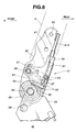
- the stopper mechanism 51 comprises a base plate 65 which is mounted on the vehicle floor "VF".
- An arm 62 is pivotally connected to the base plate 65 through a right center shaft 64.
- the right center shaft 64 and the above-mentioned left center shaft 2 are coaxial with each other, so that the seatback 4 can pivot about a common axis of these shafts 64 and 2.
- the arm 62 is secured to a lower right side of the seatback 4 by means of bolts 5. (Bolt holes 80 and 81 formed in the arm 62 through which the bolts 5 pass are shown in Fig. 8.)
- a curved follower link 7b is secured at its lower portion to a rear right side of the seat proper 9 through bolts 8 and pivotally connected at its upper end to the arm 62 through a pivot pin 6.
- the two curved followers 7a and 7b and the two pivotal support units "PSa” and “PSb” constitute a so-called seat sinking mechanism which can sink or lower the seat when the seatback 4 is folded onto the seat proper 9.
- the base plate 65 is formed at an upper portion thereof with both an arcuate recess 82 and a projected arcuate ridge 84 each being concentric with the common axis of the left and right center shafts 2 and 64.
- a stopper wall 83 is defined between the arcuate recess 82 and the arcuate ridge 84.
- the length of the arcuate recess 82 is so determined as to permit an adequate reclining movement of the seatback 4, that is, a pivotal movement of the seatback 4 between a certain rearwardly inclined position and a certain raised position.
- a lock lever 63 is pivotally connected through a shaft 86 to the arm 62. As shown, the lock lever 63 is formed at its free end with a pawl 85 which is received in the arcuate recess 82 of the base plate 65. To the pawl 85, there is pivotally connected through a pin 87 a lower end of the above-mentioned actuating wire 61 which extends from the control knob 60. A leading end of a sleeve 61A of the actuating wire 61 is fixed to a holder bracket 66 which is secured to the arm 62 to move therewith. The holder bracket 66 supports one end of the shaft 86.
- a biasing spring 67 is disposed at its turned middle portion about the shaft 86 with one end hooked to the lock lever 63 and the other end hooked to the arm 62, so that the lock lever 63 is biased to pivot in a clockwise direction in Fig. 8, that is, in a direction to put the pawl 85 of the lock lever 63 into the arcuate recess 82 of the base plate 65.
- a return spring 68 of spiral type is disposed about the center shaft 64 with an inner end held by the center shaft 64 and an outer end hooked to a pin 69 secured to the base plate 65. With this return spring 68, the seatback 4 to which the arm 62 is secured is constantly biased to pivot forwardly about the common axis of the center shafts 64 and 2. It is to be noted that the center shaft 64 and the arm 62 rotate like a single unit.
- the pawl 85 of the lock lever 63 is brought into abutment with the stopper wall 83 of the base plate 65.
- the seatback 4 can take a desired angular position within a given range determined by the movement of the pawl 85 on and along the bottom of the arcuate recess 82. That is, only when the stopper mechanism 51 assumes such an operative condition as shown in Fig. 8, the reclining mechanism 50 can provide the seatback 4 with a desired angular position.
- the reclining mechanism 50 (see Fig. 11) assumes a locked condition wherein the tooth member 20 is engaged with the toothed portion 19 having the cam 23 engaged with the guide edge 20a as shown, and the stopper mechanism 51 (see Fig. 8) assumes a condition wherein the pawl 85 of the lock lever 63 is received in the arcuate recess 82.
- the seatback 4 Upon the canceling, the seatback 4 is pivoted forward and abuts against the back of the seat occupant due to the biasing force of the return spring 68 incorporated with the stopper mechanism 51. That is, under this condition, the angular position of the seatback 4 is changeable at will within the range determined by the movement of the pawl 85 in the arcuate recess 82 (see Fig. 8) of the free-hinge mechanism.
- the actuating rod 52 (see Fig. 11) is moved downward due to the force of the spring 30. With this movement, the cam 23 is slid onto the guide edge 20a of the tooth member 20 thereby establishing an engagement between the toothed portion 19 of the tooth member 20 and the toothed portion 17 of the arm 3. Thus, the seatback 4 is locked at the desired angular position.
- the luggage space provided at the rear part of the vehicle cabin becomes increased by a degree corresponding to the area possessed by the back of the seatback 4. Due to the lowering of the seat proper 9, the back surface of the seatback 4 becomes flush with the floor of the luggage space.
- the seatback 4 When applied with an external force, the seatback 4 is raised upward moving back the pawl 85 of the lock lever 63 on the arcuate ridge 84 (see Fig. 10), and when thus the seatback 4 comes to the certain upright position, the pawl 85 falls into the arcuate recess 82 with the force of the spring 67. Upon this, the actuating wire 61 and thus the other actuating wire 58 (see Fig. 1) are permitted to move downward and thus the reclining mechanism 50 (see Fig. 11) is brought to the locked condition and the stopper mechanism 51 is brought to the operative condition as shown in Fig. 8. If the seat occupant wishes to change the angular position of the seatback 4, he or she must pull the pull tab 57.
- the handling work needed for reclining the seatback 4 to a desired angular position and folding the seatback 4 onto the seat proper 9 is very easy. Furthermore, due to provision of the stopper mechanism 51, the seat occupant is suppressed from being hardly hit by seatback 4 when he or she handles the pull tab 57. Furthermore, due to the sinking movement of the seat proper 9, the back surface of the seatback 4 folded on the seat proper 9 can provide the enlarged luggage space with an entirely flat floor.
Applications Claiming Priority (2)
| Application Number | Priority Date | Filing Date | Title |
|---|---|---|---|
| JP04703498A JP3578905B2 (ja) | 1998-02-27 | 1998-02-27 | 車両用シート |
| JP4703498 | 1998-02-27 |
Publications (3)
| Publication Number | Publication Date |
|---|---|
| EP0938997A2 true EP0938997A2 (fr) | 1999-09-01 |
| EP0938997A3 EP0938997A3 (fr) | 2001-08-01 |
| EP0938997B1 EP0938997B1 (fr) | 2004-01-21 |
Family
ID=12763899
Family Applications (1)
| Application Number | Title | Priority Date | Filing Date |
|---|---|---|---|
| EP19990103290 Expired - Lifetime EP0938997B1 (fr) | 1998-02-27 | 1999-02-19 | Siège rabattable et inclinable pour véhicule |
Country Status (3)
| Country | Link |
|---|---|
| EP (1) | EP0938997B1 (fr) |
| JP (1) | JP3578905B2 (fr) |
| DE (1) | DE69914237T2 (fr) |
Cited By (9)
| Publication number | Priority date | Publication date | Assignee | Title |
|---|---|---|---|---|
| GB2359014A (en) * | 2000-02-12 | 2001-08-15 | Johnson Controls Automotive Uk | Foldable reclining vehicle seat with dual control mechanism |
| FR2811947A1 (fr) * | 2000-07-20 | 2002-01-25 | Faure Bertrand Equipements Sa | Siege de vehicule equipe d'un mecanisme d'articulation |
| FR2816260A1 (fr) * | 2000-11-08 | 2002-05-10 | Faurecia Sieges Automobile | Mecanisme de pivotement pour siege de vehicule et siege comportant ce mecanisme |
| WO2002049873A2 (fr) * | 2000-12-20 | 2002-06-27 | Intier Automotive Inc. | Commande externe d'un ensemble inclinable |
| EP0976606B1 (fr) * | 1998-07-30 | 2004-06-16 | Fuji Kiko Company Limited | Système d'inclinaison de siège |
| FR2899162A1 (fr) * | 2006-04-03 | 2007-10-05 | Faurecia Sieges Automobile | Siege de vehicule equipe d'un mecanisme d'articulation |
| CN101883697B (zh) * | 2007-12-03 | 2012-08-15 | 丰田纺织株式会社 | 车辆用座椅 |
| US8388067B2 (en) | 2009-09-25 | 2013-03-05 | Imasen Electric Industrial Co., Ltd. | Seat apparatus |
| CN102015359B (zh) * | 2008-06-09 | 2013-03-20 | 丰田自动车株式会社 | 座椅及座椅控制方法 |
Families Citing this family (7)
| Publication number | Priority date | Publication date | Assignee | Title |
|---|---|---|---|---|
| JP4763150B2 (ja) * | 2001-05-16 | 2011-08-31 | アイシン精機株式会社 | 折り畳みシート |
| KR100461102B1 (ko) * | 2002-08-08 | 2004-12-13 | 현대자동차주식회사 | 차량용 리어시트의 리클라이닝 장치 |
| KR100501671B1 (ko) * | 2002-11-20 | 2005-07-18 | 현대자동차주식회사 | 시트백 각도 조절장치 |
| DE102005027074A1 (de) * | 2005-06-11 | 2006-12-14 | Recaro Gmbh & Co.Kg | Fahrzeugsitz, insbesondere Sportsitz |
| CN100462252C (zh) * | 2005-07-22 | 2009-02-18 | C.劳勃汉默斯坦两合有限公司 | 具有座位部分、座椅靠背和底架的车辆座椅 |
| DE102009029504A1 (de) | 2008-09-18 | 2010-03-25 | C. Rob. Hammerstein Gmbh & Co. Kg | Kraftfahrzeugsitz mit einem Sitzgestell und einer Rückenlehne |
| CN107972543B (zh) * | 2017-12-02 | 2024-03-26 | 芜湖瑞泰汽车零部件有限公司 | 一种靠背能够调节的汽车座椅结构 |
Citations (6)
| Publication number | Priority date | Publication date | Assignee | Title |
|---|---|---|---|---|
| DE3828659A1 (de) * | 1987-09-11 | 1989-03-23 | Volkswagen Ag | Gelenkbeschlag fuer einen fahrzeugsitz mit verstellbarer rueckenlehne |
| DE4142924A1 (de) * | 1991-12-24 | 1993-07-01 | Naue Johnson Controls Eng | Betaetigungsvorrichtung zum freischwenken von lehnen von kraftfahrzeugsitzen |
| JPH07117541A (ja) * | 1993-10-22 | 1995-05-09 | Suzuki Motor Corp | 格納式リヤシートのロック操作装置 |
| DE19502333A1 (de) * | 1995-01-26 | 1996-08-08 | Faure Bertrand Sitztech Gmbh | Gelenkbeschlag für Kraftfahrzeugsitze |
| US5570931A (en) * | 1995-09-29 | 1996-11-05 | Chrysler Corporation | Vehicle adjustable and stowable rear seat |
| EP0776781A2 (fr) * | 1995-10-31 | 1997-06-04 | Fujikiko Kabushiki Kaisha | Dispositif d'inclinaision de siège |
-
1998
- 1998-02-27 JP JP04703498A patent/JP3578905B2/ja not_active Expired - Fee Related
-
1999
- 1999-02-19 DE DE69914237T patent/DE69914237T2/de not_active Expired - Fee Related
- 1999-02-19 EP EP19990103290 patent/EP0938997B1/fr not_active Expired - Lifetime
Patent Citations (6)
| Publication number | Priority date | Publication date | Assignee | Title |
|---|---|---|---|---|
| DE3828659A1 (de) * | 1987-09-11 | 1989-03-23 | Volkswagen Ag | Gelenkbeschlag fuer einen fahrzeugsitz mit verstellbarer rueckenlehne |
| DE4142924A1 (de) * | 1991-12-24 | 1993-07-01 | Naue Johnson Controls Eng | Betaetigungsvorrichtung zum freischwenken von lehnen von kraftfahrzeugsitzen |
| JPH07117541A (ja) * | 1993-10-22 | 1995-05-09 | Suzuki Motor Corp | 格納式リヤシートのロック操作装置 |
| DE19502333A1 (de) * | 1995-01-26 | 1996-08-08 | Faure Bertrand Sitztech Gmbh | Gelenkbeschlag für Kraftfahrzeugsitze |
| US5570931A (en) * | 1995-09-29 | 1996-11-05 | Chrysler Corporation | Vehicle adjustable and stowable rear seat |
| EP0776781A2 (fr) * | 1995-10-31 | 1997-06-04 | Fujikiko Kabushiki Kaisha | Dispositif d'inclinaision de siège |
Non-Patent Citations (1)
| Title |
|---|
| PATENT ABSTRACTS OF JAPAN vol. 1995, no. 08, 29 September 1995 (1995-09-29) & JP 07 117541 A (SUZUKI MOTOR CORP), 9 May 1995 (1995-05-09) * |
Cited By (13)
| Publication number | Priority date | Publication date | Assignee | Title |
|---|---|---|---|---|
| EP0976606B1 (fr) * | 1998-07-30 | 2004-06-16 | Fuji Kiko Company Limited | Système d'inclinaison de siège |
| GB2359014B (en) * | 2000-02-12 | 2003-10-15 | Johnson Controls Automotive Uk | Foldable Reclining Vehicle Seat with Dual Control Mechanism |
| GB2359014A (en) * | 2000-02-12 | 2001-08-15 | Johnson Controls Automotive Uk | Foldable reclining vehicle seat with dual control mechanism |
| FR2811947A1 (fr) * | 2000-07-20 | 2002-01-25 | Faure Bertrand Equipements Sa | Siege de vehicule equipe d'un mecanisme d'articulation |
| FR2816260A1 (fr) * | 2000-11-08 | 2002-05-10 | Faurecia Sieges Automobile | Mecanisme de pivotement pour siege de vehicule et siege comportant ce mecanisme |
| WO2002049873A2 (fr) * | 2000-12-20 | 2002-06-27 | Intier Automotive Inc. | Commande externe d'un ensemble inclinable |
| WO2002049873A3 (fr) * | 2000-12-20 | 2002-09-26 | Intier Automotive Inc | Commande externe d'un ensemble inclinable |
| US6905173B2 (en) | 2000-12-20 | 2005-06-14 | Magna Seating Systems Inc. | External control of recliner assembly background of the invention |
| FR2899162A1 (fr) * | 2006-04-03 | 2007-10-05 | Faurecia Sieges Automobile | Siege de vehicule equipe d'un mecanisme d'articulation |
| CN101883697B (zh) * | 2007-12-03 | 2012-08-15 | 丰田纺织株式会社 | 车辆用座椅 |
| US8376459B2 (en) | 2007-12-03 | 2013-02-19 | Toyota Boshoku Kabushiki Kaisha | Vehicle seat |
| CN102015359B (zh) * | 2008-06-09 | 2013-03-20 | 丰田自动车株式会社 | 座椅及座椅控制方法 |
| US8388067B2 (en) | 2009-09-25 | 2013-03-05 | Imasen Electric Industrial Co., Ltd. | Seat apparatus |
Also Published As
| Publication number | Publication date |
|---|---|
| DE69914237D1 (de) | 2004-02-26 |
| EP0938997B1 (fr) | 2004-01-21 |
| JP3578905B2 (ja) | 2004-10-20 |
| DE69914237T2 (de) | 2004-12-02 |
| JPH11244082A (ja) | 1999-09-14 |
| EP0938997A3 (fr) | 2001-08-01 |
Similar Documents
| Publication | Publication Date | Title |
|---|---|---|
| EP0938997B1 (fr) | Siège rabattable et inclinable pour véhicule | |
| US5597206A (en) | Easy entry seat adjuster | |
| JP3833936B2 (ja) | シート装置 | |
| US4101169A (en) | Adjustable seat for a motor vehicle | |
| US6302485B1 (en) | Head rest device for vehicles | |
| US8047610B2 (en) | Vehicle seats | |
| US4626028A (en) | Seat for vehicles | |
| US7172253B2 (en) | Vehicle seat | |
| US5052751A (en) | Walk-in device of automotive seat having cooperating pivoted levers | |
| EP0768205B1 (fr) | Siège pour véhicules de type camionette | |
| US4491365A (en) | Thigh support adjusting mechanism for vehicle seat | |
| US4742983A (en) | Seat sliding device | |
| US6336679B1 (en) | Rotary recliner control mechanism for multifunction vehicle seat applications | |
| EP1309466B1 (fr) | Ensemble rails de guidage pour siege a memoire de position intermediaire permettant d'entrer plus facilement dans un vehicule | |
| US5605377A (en) | Vehicle seat with full memory easy entry | |
| US6733076B2 (en) | Seatback recliner mechanism incorporating forward fold flat capability from any forward rearward reclined position | |
| US6663180B2 (en) | Vehicle seat provided with a fold-down back | |
| US6832815B2 (en) | Seatback dump latch | |
| US5947560A (en) | Linear recliner with single position memory | |
| JP4143264B2 (ja) | 出入りしやすい中間位置メモリーシート | |
| US4607884A (en) | Vehicle easy entry seat latching mechanism | |
| US5567013A (en) | Seat support and slide mechanism | |
| US20040135412A1 (en) | Motor vehicle seat | |
| JP2943977B2 (ja) | 自動車の座席の折り畳み装置 | |
| EP1407919B1 (fr) | Levier de commande et siege equipe d'un tel levier |
Legal Events
| Date | Code | Title | Description |
|---|---|---|---|
| PUAI | Public reference made under article 153(3) epc to a published international application that has entered the european phase |
Free format text: ORIGINAL CODE: 0009012 |
|
| 17P | Request for examination filed |
Effective date: 19990219 |
|
| AK | Designated contracting states |
Kind code of ref document: A2 Designated state(s): DE FR GB |
|
| AX | Request for extension of the european patent |
Free format text: AL;LT;LV;MK;RO;SI |
|
| PUAL | Search report despatched |
Free format text: ORIGINAL CODE: 0009013 |
|
| AK | Designated contracting states |
Kind code of ref document: A3 Designated state(s): AT BE CH CY DE DK ES FI FR GB GR IE IT LI LU MC NL PT SE |
|
| AX | Request for extension of the european patent |
Free format text: AL;LT;LV;MK;RO;SI |
|
| AKX | Designation fees paid |
Free format text: DE FR GB |
|
| GRAH | Despatch of communication of intention to grant a patent |
Free format text: ORIGINAL CODE: EPIDOS IGRA |
|
| GRAS | Grant fee paid |
Free format text: ORIGINAL CODE: EPIDOSNIGR3 |
|
| GRAA | (expected) grant |
Free format text: ORIGINAL CODE: 0009210 |
|
| AK | Designated contracting states |
Kind code of ref document: B1 Designated state(s): DE FR GB |
|
| RAP1 | Party data changed (applicant data changed or rights of an application transferred) |
Owner name: SUZUKI MOTOR CORPORATION Owner name: FUJI KIKO COMPANY LIMITED |
|
| REG | Reference to a national code |
Ref country code: GB Ref legal event code: FG4D |
|
| REF | Corresponds to: |
Ref document number: 69914237 Country of ref document: DE Date of ref document: 20040226 Kind code of ref document: P |
|
| ET | Fr: translation filed | ||
| PLBE | No opposition filed within time limit |
Free format text: ORIGINAL CODE: 0009261 |
|
| STAA | Information on the status of an ep patent application or granted ep patent |
Free format text: STATUS: NO OPPOSITION FILED WITHIN TIME LIMIT |
|
| 26N | No opposition filed |
Effective date: 20041022 |
|
| PGFP | Annual fee paid to national office [announced via postgrant information from national office to epo] |
Ref country code: GB Payment date: 20070214 Year of fee payment: 9 |
|
| PGFP | Annual fee paid to national office [announced via postgrant information from national office to epo] |
Ref country code: DE Payment date: 20070328 Year of fee payment: 9 |
|
| PGFP | Annual fee paid to national office [announced via postgrant information from national office to epo] |
Ref country code: FR Payment date: 20070209 Year of fee payment: 9 |
|
| GBPC | Gb: european patent ceased through non-payment of renewal fee |
Effective date: 20080219 |
|
| REG | Reference to a national code |
Ref country code: FR Ref legal event code: ST Effective date: 20081031 |
|
| PG25 | Lapsed in a contracting state [announced via postgrant information from national office to epo] |
Ref country code: DE Free format text: LAPSE BECAUSE OF NON-PAYMENT OF DUE FEES Effective date: 20080902 |
|
| PG25 | Lapsed in a contracting state [announced via postgrant information from national office to epo] |
Ref country code: FR Free format text: LAPSE BECAUSE OF NON-PAYMENT OF DUE FEES Effective date: 20080229 |
|
| PG25 | Lapsed in a contracting state [announced via postgrant information from national office to epo] |
Ref country code: GB Free format text: LAPSE BECAUSE OF NON-PAYMENT OF DUE FEES Effective date: 20080219 |