EP0937939B1 - Verfahren zur Isolierung von gekrümmten Flächen - Google Patents
Verfahren zur Isolierung von gekrümmten Flächen Download PDFInfo
- Publication number
- EP0937939B1 EP0937939B1 EP99101644A EP99101644A EP0937939B1 EP 0937939 B1 EP0937939 B1 EP 0937939B1 EP 99101644 A EP99101644 A EP 99101644A EP 99101644 A EP99101644 A EP 99101644A EP 0937939 B1 EP0937939 B1 EP 0937939B1
- Authority
- EP
- European Patent Office
- Prior art keywords
- vacuum
- layer
- destroyed
- moulded element
- molded body
- Prior art date
- Legal status (The legal status is an assumption and is not a legal conclusion. Google has not performed a legal analysis and makes no representation as to the accuracy of the status listed.)
- Expired - Lifetime
Links
- 238000009413 insulation Methods 0.000 title claims description 22
- 238000000034 method Methods 0.000 title claims description 12
- 239000011810 insulating material Substances 0.000 claims description 6
- 239000002390 adhesive tape Substances 0.000 claims description 4
- 239000002184 metal Substances 0.000 claims description 4
- 239000010779 crude oil Substances 0.000 claims description 2
- 239000011888 foil Substances 0.000 claims description 2
- 238000010438 heat treatment Methods 0.000 claims description 2
- 239000002985 plastic film Substances 0.000 claims description 2
- 229920006255 plastic film Polymers 0.000 claims description 2
- 239000002759 woven fabric Substances 0.000 claims 1
- 239000010410 layer Substances 0.000 description 28
- 230000000694 effects Effects 0.000 description 6
- 239000000835 fiber Substances 0.000 description 3
- 239000012774 insulation material Substances 0.000 description 3
- 239000011230 binding agent Substances 0.000 description 2
- 239000002657 fibrous material Substances 0.000 description 2
- 239000000463 material Substances 0.000 description 2
- 229910044991 metal oxide Inorganic materials 0.000 description 2
- 150000004706 metal oxides Chemical class 0.000 description 2
- 238000000465 moulding Methods 0.000 description 2
- 244000089486 Phragmites australis subsp australis Species 0.000 description 1
- 229920000297 Rayon Polymers 0.000 description 1
- 239000003795 chemical substances by application Substances 0.000 description 1
- 239000002131 composite material Substances 0.000 description 1
- 238000000354 decomposition reaction Methods 0.000 description 1
- 239000004744 fabric Substances 0.000 description 1
- 239000000945 filler Substances 0.000 description 1
- 238000012423 maintenance Methods 0.000 description 1
- 239000010445 mica Substances 0.000 description 1
- 229910052618 mica group Inorganic materials 0.000 description 1
- 238000003801 milling Methods 0.000 description 1
- 239000000203 mixture Substances 0.000 description 1
- 239000003605 opacifier Substances 0.000 description 1
- 229910001562 pearlite Inorganic materials 0.000 description 1
- 239000011148 porous material Substances 0.000 description 1
- 238000007789 sealing Methods 0.000 description 1
- 239000002356 single layer Substances 0.000 description 1
- 239000000126 substance Substances 0.000 description 1
- 239000010455 vermiculite Substances 0.000 description 1
- 229910052902 vermiculite Inorganic materials 0.000 description 1
- 235000019354 vermiculite Nutrition 0.000 description 1
Images


Classifications
-
- F—MECHANICAL ENGINEERING; LIGHTING; HEATING; WEAPONS; BLASTING
- F16—ENGINEERING ELEMENTS AND UNITS; GENERAL MEASURES FOR PRODUCING AND MAINTAINING EFFECTIVE FUNCTIONING OF MACHINES OR INSTALLATIONS; THERMAL INSULATION IN GENERAL
- F16L—PIPES; JOINTS OR FITTINGS FOR PIPES; SUPPORTS FOR PIPES, CABLES OR PROTECTIVE TUBING; MEANS FOR THERMAL INSULATION IN GENERAL
- F16L59/00—Thermal insulation in general
- F16L59/06—Arrangements using an air layer or vacuum
- F16L59/065—Arrangements using an air layer or vacuum using vacuum
-
- F—MECHANICAL ENGINEERING; LIGHTING; HEATING; WEAPONS; BLASTING
- F16—ENGINEERING ELEMENTS AND UNITS; GENERAL MEASURES FOR PRODUCING AND MAINTAINING EFFECTIVE FUNCTIONING OF MACHINES OR INSTALLATIONS; THERMAL INSULATION IN GENERAL
- F16L—PIPES; JOINTS OR FITTINGS FOR PIPES; SUPPORTS FOR PIPES, CABLES OR PROTECTIVE TUBING; MEANS FOR THERMAL INSULATION IN GENERAL
- F16L59/00—Thermal insulation in general
- F16L59/06—Arrangements using an air layer or vacuum
-
- F—MECHANICAL ENGINEERING; LIGHTING; HEATING; WEAPONS; BLASTING
- F16—ENGINEERING ELEMENTS AND UNITS; GENERAL MEASURES FOR PRODUCING AND MAINTAINING EFFECTIVE FUNCTIONING OF MACHINES OR INSTALLATIONS; THERMAL INSULATION IN GENERAL
- F16L—PIPES; JOINTS OR FITTINGS FOR PIPES; SUPPORTS FOR PIPES, CABLES OR PROTECTIVE TUBING; MEANS FOR THERMAL INSULATION IN GENERAL
- F16L59/00—Thermal insulation in general
- F16L59/02—Shape or form of insulating materials, with or without coverings integral with the insulating materials
- F16L59/026—Mattresses, mats, blankets or the like
-
- Y—GENERAL TAGGING OF NEW TECHNOLOGICAL DEVELOPMENTS; GENERAL TAGGING OF CROSS-SECTIONAL TECHNOLOGIES SPANNING OVER SEVERAL SECTIONS OF THE IPC; TECHNICAL SUBJECTS COVERED BY FORMER USPC CROSS-REFERENCE ART COLLECTIONS [XRACs] AND DIGESTS
- Y02—TECHNOLOGIES OR APPLICATIONS FOR MITIGATION OR ADAPTATION AGAINST CLIMATE CHANGE
- Y02E—REDUCTION OF GREENHOUSE GAS [GHG] EMISSIONS, RELATED TO ENERGY GENERATION, TRANSMISSION OR DISTRIBUTION
- Y02E50/00—Technologies for the production of fuel of non-fossil origin
- Y02E50/10—Biofuels, e.g. bio-diesel
-
- Y—GENERAL TAGGING OF NEW TECHNOLOGICAL DEVELOPMENTS; GENERAL TAGGING OF CROSS-SECTIONAL TECHNOLOGIES SPANNING OVER SEVERAL SECTIONS OF THE IPC; TECHNICAL SUBJECTS COVERED BY FORMER USPC CROSS-REFERENCE ART COLLECTIONS [XRACs] AND DIGESTS
- Y10—TECHNICAL SUBJECTS COVERED BY FORMER USPC
- Y10T—TECHNICAL SUBJECTS COVERED BY FORMER US CLASSIFICATION
- Y10T428/00—Stock material or miscellaneous articles
- Y10T428/23—Sheet including cover or casing
- Y10T428/231—Filled with gas other than air; or under vacuum
-
- Y—GENERAL TAGGING OF NEW TECHNOLOGICAL DEVELOPMENTS; GENERAL TAGGING OF CROSS-SECTIONAL TECHNOLOGIES SPANNING OVER SEVERAL SECTIONS OF THE IPC; TECHNICAL SUBJECTS COVERED BY FORMER USPC CROSS-REFERENCE ART COLLECTIONS [XRACs] AND DIGESTS
- Y10—TECHNICAL SUBJECTS COVERED BY FORMER USPC
- Y10T—TECHNICAL SUBJECTS COVERED BY FORMER US CLASSIFICATION
- Y10T428/00—Stock material or miscellaneous articles
- Y10T428/24—Structurally defined web or sheet [e.g., overall dimension, etc.]
- Y10T428/24479—Structurally defined web or sheet [e.g., overall dimension, etc.] including variation in thickness
- Y10T428/2457—Parallel ribs and/or grooves
Definitions
- the invention relates to a method for heat insulation of curved surfaces, especially pipes using a heat-insulating molded body, the compressed and optionally hardened, microporous insulating material in one or contains several enveloped and evacuated layers and a surface with a lamellar structure has, the slats a depth of 40 to 95% of the thickness of the Have molded body.
- DE-4432896 A1 describes an evacuated gas-tight enclosure, heat-insulating molded body on the basis of pressed and optionally hardened, microporous insulating material disclosed.
- EP-69543 A2 discloses a molded body for the insulation of pipes.
- the present invention provides a method by which effective thermal insulation of curved surfaces is possible.
- the invention relates to a method for insulating curved surfaces with a plate-shaped, evacuated and heat-insulating molded body that is pressed and optionally hardened, microporous insulating material in one or more encased and contains evacuated layers and has a surface with a lamellar structure, the lamellae having a depth of 40 to 95% of the thickness of the shaped body, which is characterized in that the shaped body with the surface with lamellar structure is snuggled to the curved surface and fixed and the vacuum in at least one layer is canceled.
- a multi-layer structure is required preferred of the shaped body, consisting of two to five or more layers.
- the Layers can be arranged so that there is an offset in the joints, so that a further reduction in heat loss is the result.
- the thermal conductivity of an insulation material can be drastically reduced by reducing the air pressure in the system.
- the efficiency of a microporous insulation material can be improved up to a factor of 10 if the partial pressure within the insulation material is reduced below 5 to 10 mbar, the level of the vacuum determining the effectiveness of the thermal insulation.
- a particularly efficient thermal insulation is achieved if the molded body used for the thermal insulation has a multi-layer design and the vacuum is not released for all layers, and at least one layer remains in an evacuated state. The stability of the remaining vacuum can be maintained for years through the use of suitable coverings, for example multilayer films.
- the shaped body according to Figure 1 is plate-shaped and consists entirely or partially microporous insulating material 1 and a gas-tight envelope 2 (only partially and shown schematically). It has a surface with elongated incisions 3 (slats) is structured
- the slats have a depth t of 40 to 95%, particularly preferably from 60 to 85% of the thickness d of the shaped body.
- a depth t is typical of at least 5 mm.
- the thickness d of the molded body results from the desired thermal insulation effect.
- the need to use the slats in the shaped bodies, pipes with wall thicknesses> 5% of the pipe diameter result for small pipes (diameter approx.
- the rigidity of the molded body which mainly depends on its density plays a role here.
- the slats are preferably at a distance of 4 to 40 mm, particularly preferably of 10 up to 20 mm next to each other and preferably arranged parallel to each other and have a base width b of 0.5 to 5 mm, preferably from 1 to 3 mm.
- Your cross section has preferably a square, rectangular, acute-angled or rounded shape, especially preferably one of the forms shown in FIG. 2A-2D.
- the distance between the slats depend on the one hand on the selected basic width and on the other hand on the inner diameter to be achieved. If you add the base widths of each Slats, should be approximately the difference between the outer and inner circumference of the molded body lying against the curved surface.
- the shaped body with its structured surface nestled and fixed on the curved surface and then the vacuum canceled.
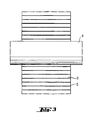
- This is indicated by the example of the insulation of a pipe 4 in FIG. 3.
- the enveloped molded body 5 is placed around the tube 4, the one provided with fins Surface comes to lie on the circumferential surface of the tube. Due to the slat structure the molded body can be bent according to the contour of the tube, even if the thickness d is relatively large and / or the radius of curvature of the tube is comparatively large is small.
- the method is preferably used for pipe insulation, for example Pipelines for crude oil and district heating pipes, used by engines, turbines and chimneys.
- a molded body which consists of several enveloped and evacuated Layers (an inner layer 6, a middle layer 7 and an outer layer 8) is built, the compressed and optionally contain hardened, microporous insulating material.
- an inner layer 6, a middle layer 7 and an outer layer 8 is built, the compressed and optionally contain hardened, microporous insulating material.
- the surface of the molded body with its lamellar structure is attached to the curved surface and nestled and then the vacuum in at least one layer is removed, it being preferred that the vacuum be in at least one other Layer remains intact. It is particularly preferred that the vacuum in the curved Surface adjacent layer lifted and in at least one other Layer is permanently maintained.
- the molded body can be in its entirety or in layers, for example on a pipe 4 glued or otherwise fixed thereon, for example by a tape, preferably a fabric tape or adhesive tape, a plastic film or a metal foil around the molded body lying against the tube or one layer of the molded body each becomes. It can also be a metal sheet in the form of whole or half shells or suitable Cuts are placed around the pipe and fixed. That which is maintained in the molded body Vacuum is released in at least one of the layers to possibly exist Reduce remaining thermal insulation leaks or eliminate them completely. When the vacuum is released, the volume of the shaped body increases inflowing air, and the expanding molding can create gaps and gaps conclude.
- the vacuum can be released by wrapping the layer and if necessary, intentionally use a tool to fix the molded body is damaged or even by the wrapping by exposure to the environment or is mechanically or thermally stressed during its use until it is tears or thermally decomposes.
- the latter can, for example, at Thermal insulation of pipelines due to the medium temperatures of up to 180 ° C happen, with a suitable choice of the material of the sheath in multilayer Structure of the molded body only the decomposition of the inner layer underneath Maintenance of the vacuum can be achieved in layers lying further out.
- the molded article required for carrying out the invention is preferably produced by a process which has already been described in DE-4432896 A1. It also preferably has the composition mentioned there of 30 to 100% by weight of finely divided metal oxide, 0 to 50% by weight of opacifier, 0 to 50% by weight of fiber material and 0 to 15% by weight of inorganic binder. It is also preferred to select metal oxide, fiber material, opacifying agent and binder from the substances mentioned in DE-4432896 A1, organic fibers, for example viscose fibers, also being suitable as fibers. Fillers such as mica, pearlite or vermiculite may also be present.
- the lamellae are cut using milling or sawing tools, for example, saws or wire saws cut and the molded body into one Envelope introduced, evacuated, and the envelope sealed.
- Providing Channel pores and channels in the molded body to accelerate the evacuation, as described in DE-4432896 A1 is useful, but not absolutely necessary.
- a plate with the dimensions 965 mm * 500 mm * 20 mm was made with 50 parallel incisions provided at a distance of 19.6 mm.
- the incisions had a base width of 2.5 mm.
- the plate thus obtained became smaller in a multilayer composite film at pressures 200 mbar welded airtight, the originally flat plate already a little curved and thus acts as a handling aid during assembly; shorter assembly times can be the result.
- the plate was then made with the incisions provided surface mounted on a tube and fixed point by point with adhesive tape. Subsequently the envelope was scratched with a sharp object and the Tube wrapped tightly around the tube with the adhesive tape.
- a pipe carrying up to several hundred degrees of hot medium is made with three layers made of evacuated plates sealed in a gas-tight multilayer film with a lamellar structure introduced into the surface with a thickness of 12 mm each, so that the joints are staggered on the face side and in the circumference. Every single layer we fixed with tape.
- the first layer is used due to the temperature resistance the wrapping film thermally decomposes, so that the sealing effect takes effect. Because of the heat-insulating effect of the first layer, the covering remains of the next layers, which is due to the particularly good thermal insulation effect of the evacuated systems results in an optimal insulation effect.
Landscapes
- Engineering & Computer Science (AREA)
- General Engineering & Computer Science (AREA)
- Mechanical Engineering (AREA)
- Thermal Insulation (AREA)
- Moulds For Moulding Plastics Or The Like (AREA)
Description
Eine besonders effiziente Wärmedämmung wird erreicht, wenn der zur Wärmedämmung eingesetzte Formkörper mehrschichtig ausgebildet ist und das Vakuum nicht bei allen Schichten aufgehoben wird, und mindestens eine Schicht in evakuiertem Zustand bleibt. Durch die Verwendung von geeigneten Umhüllungen, beispielsweise mehrschichtigen Folien, kann die Stabilität des verbleibenden Vakuums über Jahre hinweg erhalten bleiben.
0 bis 50 Gew.-% Trübungsmittel, 0 bis 50 Gew.-% Fasermaterial und 0 bis 15 Gew.-% anorganischem Bindemittel. Bevorzugt ist auch, Metalloxid, Fasermaterial, Trübungsmittel und Bindemittel unter den in der DE-4432896 A1 genannten Stoffen auszuwählen, wobei als Fasem auch organische Fasern, beispielsweise Viskosefasem in Frage kommen. Auch Füllstoffe wie Glimmer, Perlit oder Vermiculit können gegebenenfalls enthalten sein.
Claims (7)
- Verfahren zur Isolierung von gekrümmten Flächen mit einem plattenförmigen, evakuierten und wärmedämmenden Formkörper, der verpreßtes und gegebenenfalls gehärtetes, mikroporöses Isoliermaterial in einer oder mehreren umhüllten und evakuierten Schichten enthält und eine Oberfläche mit Lamellenstruktur aufweist, wobei die Lamellen eine Tiefe von 40 bis 95% der Dicke des Formkörpers besitzen, das dadurch gekennzeichnet ist, daß der Förmkörper mit der Oberfläche mit Lamellenstruktur an die gekrümmte Fläche angeschmiegt und fixiert wird und das Vakuum in mindestens einer Schicht aufgehoben wird.
- Verfahren nach Anspruch 1, dadurch gekennzeichnet, daß der Formkörper durch Umwickeln mit einem Gewebeband, Klebeband, einer Kunststoff- oder Metallfolie oder mit zugeschnittenem Metallblech fixiert wird.
- Verfahren nach Anspruch 1, dadurch gekennzeichnet, daß das Vakuum aufgehoben wird, indem die Umhüllung der Schicht mit einem Werkzeug beschädigt wird.
- Verfahren nach Anspruch 1, dadurch gekennzeichnet, daß das Vakuum aufgehoben wird, indem die Umhüllung der Schicht teilweise thermisch zersetzt wird.
- Verfahren nach Anspruch 1, dadurch gekennzeichnet, daß das Vakuum von mindestens einer Schicht bei mehrschichtigen Aufbauten aufgehoben wird, indem die Umhüllung mechanisch beansprucht wird, bis sie reißt.
- Verfahren nach einem der Ansprüche 1 bis 5, dadurch gekennzeichnet, daß das Vakuum in der an die gekrümmte Fläche anliegenden Schicht aufgehoben wird und in mindestens einer anderen Schicht dauerhaft beibehalten wird.
- Verfahren nach einem der Ansprüche 1 bis 6, dadurch gekennzeichnet, daß mit dem Formkörper Rohre, beispielsweise Pipelines für Rohöl und Femwärmeleitungen, Motoren, Turbinen und Kamine isoliert werden.
Applications Claiming Priority (4)
| Application Number | Priority Date | Filing Date | Title |
|---|---|---|---|
| DE19806993 | 1998-02-19 | ||
| DE19806993 | 1998-02-19 | ||
| DE19836830 | 1998-08-13 | ||
| DE1998136830 DE19836830A1 (de) | 1998-08-13 | 1998-08-13 | Plattenförmiger, evakuierter Formkörper, Verfahren zur Wärmeisolierung und Verwendung des Formkörpers |
Publications (2)
| Publication Number | Publication Date |
|---|---|
| EP0937939A1 EP0937939A1 (de) | 1999-08-25 |
| EP0937939B1 true EP0937939B1 (de) | 2000-08-02 |
Family
ID=26043987
Family Applications (1)
| Application Number | Title | Priority Date | Filing Date |
|---|---|---|---|
| EP99101644A Expired - Lifetime EP0937939B1 (de) | 1998-02-19 | 1999-02-04 | Verfahren zur Isolierung von gekrümmten Flächen |
Country Status (10)
| Country | Link |
|---|---|
| US (1) | US6110310A (de) |
| EP (1) | EP0937939B1 (de) |
| JP (1) | JP3187384B2 (de) |
| KR (1) | KR100377338B1 (de) |
| AU (1) | AU740723B2 (de) |
| BR (1) | BR9900750A (de) |
| CA (1) | CA2262023C (de) |
| DE (1) | DE59900006D1 (de) |
| NO (1) | NO990754L (de) |
| TW (1) | TW394831B (de) |
Cited By (3)
| Publication number | Priority date | Publication date | Assignee | Title |
|---|---|---|---|---|
| DE10308581A1 (de) * | 2003-02-27 | 2004-09-16 | Wacker-Chemie Gmbh | Wärmedämmung für Unterwasser-Bauteile für die Öl- und Gasförderung |
| EP1475486A1 (de) | 2003-05-08 | 2004-11-10 | Wacker-Chemie GmbH | Vakuumisolationspaneel |
| DE102011121383A1 (de) | 2011-12-19 | 2013-06-20 | Benteler Automobiltechnik Gmbh | Isolierte Abgasleitung für eine Brennkraftmaschine |
Families Citing this family (22)
| Publication number | Priority date | Publication date | Assignee | Title |
|---|---|---|---|---|
| AT406064B (de) * | 1993-06-02 | 2000-02-25 | Evg Entwicklung Verwert Ges | Bauelement |
| DE19941746A1 (de) * | 1999-09-02 | 2001-03-08 | Porextherm Daemmstoffe Gmbh | Dämmformkörper und Verfahren zu dessen Herstellung |
| IT1318099B1 (it) * | 2000-06-30 | 2003-07-23 | Getters Spa | Pannello evacuato per l'isolamento termico di corpi cilindrici |
| ITMI20011458A1 (it) * | 2001-07-09 | 2003-01-09 | Getters Spa | Sistema per l'isolamento termico di corpi tubolari |
| ITMI20012812A1 (it) | 2001-12-27 | 2003-06-27 | Getters Spa | Metodo per la produzione di pannelli evacuati cilindrici termicamenteisolanti e pannelli cosi' ottenuti |
| ITMI20021093A1 (it) * | 2002-05-21 | 2003-11-21 | Getters Spa | Dispositivo termoisolante |
| PL1612468T3 (pl) * | 2004-07-02 | 2007-07-31 | Brugg Rohr Ag Holding | Rura przewodowa |
| US20060272727A1 (en) * | 2005-06-06 | 2006-12-07 | Dinon John L | Insulated pipe and method for preparing same |
| JP2007092776A (ja) * | 2005-09-27 | 2007-04-12 | Toshiba Home Technology Corp | 断熱材およびその製造方法 |
| JP4679324B2 (ja) * | 2005-09-30 | 2011-04-27 | イビデン株式会社 | 断熱材 |
| GB2442240A (en) * | 2006-09-29 | 2008-04-02 | Specialist Insulation Ltd | Insulating products |
| JP4897473B2 (ja) * | 2006-12-26 | 2012-03-14 | 倉敷紡績株式会社 | 真空断熱材 |
| JP4906773B2 (ja) * | 2008-04-07 | 2012-03-28 | 三菱電機株式会社 | 貯湯式給湯器 |
| US8381458B2 (en) | 2008-12-17 | 2013-02-26 | Genpak Llc | Vent baffles |
| JP5398604B2 (ja) * | 2010-03-17 | 2014-01-29 | 三菱電機株式会社 | 真空断熱材およびその製造方法 |
| JP2012163258A (ja) * | 2011-02-07 | 2012-08-30 | Mitsubishi Electric Corp | 貯湯式給湯装置 |
| JP5197812B2 (ja) * | 2011-08-26 | 2013-05-15 | 三菱電機株式会社 | 貯湯式給湯器 |
| CA2768697A1 (en) * | 2012-02-15 | 2013-08-15 | Ronald William Shaw | Insulated/soffit rafter vent |
| KR101579366B1 (ko) | 2013-02-08 | 2015-12-22 | 오씨아이 주식회사 | 진공단열재의 곡면 형성 방법 및 곡면이 형성된 진공단열재를 이용한 냉온 정수 장치 |
| JP5512011B2 (ja) * | 2013-03-27 | 2014-06-04 | 三菱電機株式会社 | 断熱箱用の真空断熱材 |
| US10435136B2 (en) | 2016-02-19 | 2019-10-08 | Bell Helicopter Textron Inc. | Driveshaft thermal barrier |
| EP4632261A1 (de) * | 2024-04-08 | 2025-10-15 | Uponor Innovation AB | Steigleitungssystem zur bereitstellung von wärme und wasser in gebäuden |
Family Cites Families (10)
| Publication number | Priority date | Publication date | Assignee | Title |
|---|---|---|---|---|
| CA861470A (en) * | 1968-10-05 | 1971-01-19 | Gulf Oil Canada Limited | Thermal insulation and thermally insulated device |
| FI66478C (fi) * | 1981-07-06 | 1984-10-10 | Partek Ab | Roerskaolelement och saett att framstaella detsamma |
| EP0090191B1 (de) * | 1982-03-27 | 1986-08-13 | BROWN, BOVERI & CIE Aktiengesellschaft | Thermische Isolierung |
| US4444098A (en) * | 1982-05-28 | 1984-04-24 | Deere & Company | Cylindrical baler with self-cleaning gate |
| DE3630399A1 (de) * | 1986-09-06 | 1988-03-17 | Messerschmitt Boelkow Blohm | Vakuum-waermeisolation |
| US5445857A (en) * | 1992-12-28 | 1995-08-29 | Praxair Technology, Inc. | Textured vacuum insulation panel |
| DE4432896C2 (de) * | 1994-09-15 | 2002-08-29 | Wacker Chemie Gmbh | Evakuierter, wärmedämmender Formkörper |
| WO1996032605A1 (en) * | 1995-04-13 | 1996-10-17 | Imperial Chemical Industries Plc | Non-planar evacuated insulation panels and a method for making same |
| DE19652731A1 (de) * | 1995-12-19 | 1997-10-30 | Helmut Schmidt | Thermische Isolierung, Verfahren zu ihrer Herstellung sowie damit isolierte Gegenstände |
| WO1998029309A1 (en) * | 1996-12-23 | 1998-07-09 | Vacupanel, Inc. | Vacuum insulated panel, container and production method |
-
1999
- 1999-02-04 EP EP99101644A patent/EP0937939B1/de not_active Expired - Lifetime
- 1999-02-04 DE DE59900006T patent/DE59900006D1/de not_active Expired - Lifetime
- 1999-02-10 US US09/248,028 patent/US6110310A/en not_active Expired - Fee Related
- 1999-02-12 KR KR10-1999-0004947A patent/KR100377338B1/ko not_active Expired - Fee Related
- 1999-02-12 TW TW088102351A patent/TW394831B/zh not_active IP Right Cessation
- 1999-02-15 CA CA002262023A patent/CA2262023C/en not_active Expired - Fee Related
- 1999-02-16 AU AU17331/99A patent/AU740723B2/en not_active Ceased
- 1999-02-16 JP JP03727799A patent/JP3187384B2/ja not_active Expired - Fee Related
- 1999-02-18 NO NO990754A patent/NO990754L/no not_active Application Discontinuation
- 1999-02-18 BR BR9900750-9A patent/BR9900750A/pt active Search and Examination
Cited By (4)
| Publication number | Priority date | Publication date | Assignee | Title |
|---|---|---|---|---|
| DE10308581A1 (de) * | 2003-02-27 | 2004-09-16 | Wacker-Chemie Gmbh | Wärmedämmung für Unterwasser-Bauteile für die Öl- und Gasförderung |
| EP1475486A1 (de) | 2003-05-08 | 2004-11-10 | Wacker-Chemie GmbH | Vakuumisolationspaneel |
| DE102011121383A1 (de) | 2011-12-19 | 2013-06-20 | Benteler Automobiltechnik Gmbh | Isolierte Abgasleitung für eine Brennkraftmaschine |
| EP2607772A1 (de) | 2011-12-19 | 2013-06-26 | Benteler Automobiltechnik GmbH | Isolierte Abgasleitung für eine Brennkraftmaschine |
Also Published As
| Publication number | Publication date |
|---|---|
| EP0937939A1 (de) | 1999-08-25 |
| CA2262023C (en) | 2003-09-30 |
| NO990754D0 (no) | 1999-02-18 |
| JP3187384B2 (ja) | 2001-07-11 |
| TW394831B (en) | 2000-06-21 |
| AU1733199A (en) | 1999-09-02 |
| DE59900006D1 (de) | 2000-09-07 |
| JPH11280989A (ja) | 1999-10-15 |
| NO990754L (no) | 1999-08-20 |
| CA2262023A1 (en) | 1999-08-19 |
| KR100377338B1 (ko) | 2003-03-28 |
| KR19990072618A (ko) | 1999-09-27 |
| US6110310A (en) | 2000-08-29 |
| AU740723B2 (en) | 2001-11-15 |
| BR9900750A (pt) | 1999-12-21 |
Similar Documents
| Publication | Publication Date | Title |
|---|---|---|
| EP0937939A1 (de) | Plattenförmiger, evakuierter Formkörper und Verfahren zur Wärmeisolierung | |
| EP2564108B1 (de) | Evakuiertes flächengebilde zur wärmedämmung | |
| US5116689A (en) | Apparatus and method for selectively increasing density and thermal conductivity of honeycomb structures | |
| DE2829333C2 (de) | Hochtemperatur-Verbunddichtung | |
| DE69535351T2 (de) | Metallischer Wärmeisolator | |
| EP3023569B2 (de) | Abstandhalter für die beabstandung von glasscheiben eines mehrfachverglasten fensters | |
| EP0164006A1 (de) | Wärmedämmformkörper mit Umhüllung | |
| CH693926A5 (de) | Geformte mehrschichtige Metallschichtenstrukturen und Verfahren zu ihrer Herstellung. | |
| WO2008141689A1 (de) | Vakuum-isolationspaneel und herstellungsverfahren dafür | |
| DE102006039621A1 (de) | Vakuumisolationspaneel mit Durchführung | |
| DE102013104712A1 (de) | Verfahren zur Herstellung von Vakuum-Isolations-Paneelen | |
| EP2584134B1 (de) | Verfahren zur Abdichtung bei der Fenstersanierung | |
| DE19803063A1 (de) | Verfahren zur Halterung und Isolation von Keramikmonolithen in einer Kraftfahrzeug-Abgasanlage einschließlich hiernach gefertigte Lagerung | |
| DE20303698U1 (de) | Wärmeisoliertes Leitungsrohr | |
| DE112005000069B4 (de) | Vakuum-Wärmeisoliermaterial, Wärmeisolier-Vorrichtung, in der dieses Material verwendet wird und Kühl-Gefrier-Vorrichtung | |
| EP2119842B1 (de) | Dämmelement und Verfahren zum Herstellen des Dämmelements | |
| EP0315169B1 (de) | Wärmedämmformkörper mit Umhüllung | |
| DE4432896C2 (de) | Evakuierter, wärmedämmender Formkörper | |
| DE3602866C2 (de) | Schaumstoffisolierrohr für Heizungsrohre mit dazugehörender Befestigungsvorrichtung | |
| DE102016013199A1 (de) | Vakuumisolationspaneel | |
| EP2119841B1 (de) | Dämmelement und Verfahren zum Herstellen des Dämmelements | |
| DE19836830A1 (de) | Plattenförmiger, evakuierter Formkörper, Verfahren zur Wärmeisolierung und Verwendung des Formkörpers | |
| DE3603069A1 (de) | Verfahren zum herstellen formsteifer verbundschichtelemente und nach dem verfahren hergestellte verbundschichtelemente | |
| EP1898014A2 (de) | Vakuumisolationspaneel mit Aussparung im Dämmstoffstützkörper | |
| DE202008009248U1 (de) | Wärmedämmendes, plattenförmiges Bauelement für Wand- oder Fußbodenheizungssysteme |
Legal Events
| Date | Code | Title | Description |
|---|---|---|---|
| PUAI | Public reference made under article 153(3) epc to a published international application that has entered the european phase |
Free format text: ORIGINAL CODE: 0009012 |
|
| 17P | Request for examination filed |
Effective date: 19990204 |
|
| AK | Designated contracting states |
Kind code of ref document: A1 Designated state(s): BE DE FI FR GB IT NL SE |
|
| AX | Request for extension of the european patent |
Free format text: AL;LT;LV;MK;RO;SI |
|
| 17Q | First examination report despatched |
Effective date: 19990714 |
|
| GRAG | Despatch of communication of intention to grant |
Free format text: ORIGINAL CODE: EPIDOS AGRA |
|
| RTI1 | Title (correction) |
Free format text: METHOD OF INSULATION OF CURVED SURFACES |
|
| GRAG | Despatch of communication of intention to grant |
Free format text: ORIGINAL CODE: EPIDOS AGRA |
|
| GRAH | Despatch of communication of intention to grant a patent |
Free format text: ORIGINAL CODE: EPIDOS IGRA |
|
| GRAH | Despatch of communication of intention to grant a patent |
Free format text: ORIGINAL CODE: EPIDOS IGRA |
|
| AKX | Designation fees paid |
Free format text: BE DE FI FR GB IT NL SE |
|
| GRAA | (expected) grant |
Free format text: ORIGINAL CODE: 0009210 |
|
| AK | Designated contracting states |
Kind code of ref document: B1 Designated state(s): BE DE FI FR GB IT NL SE |
|
| PG25 | Lapsed in a contracting state [announced via postgrant information from national office to epo] |
Ref country code: IT Free format text: LAPSE BECAUSE OF FAILURE TO SUBMIT A TRANSLATION OF THE DESCRIPTION OR TO PAY THE FEE WITHIN THE PRESCRIBED TIME-LIMIT;WARNING: LAPSES OF ITALIAN PATENTS WITH EFFECTIVE DATE BEFORE 2007 MAY HAVE OCCURRED AT ANY TIME BEFORE 2007. THE CORRECT EFFECTIVE DATE MAY BE DIFFERENT FROM THE ONE RECORDED. Effective date: 20000802 |
|
| REF | Corresponds to: |
Ref document number: 59900006 Country of ref document: DE Date of ref document: 20000907 |
|
| ET | Fr: translation filed | ||
| GBT | Gb: translation of ep patent filed (gb section 77(6)(a)/1977) |
Effective date: 20000901 |
|
| PLBE | No opposition filed within time limit |
Free format text: ORIGINAL CODE: 0009261 |
|
| STAA | Information on the status of an ep patent application or granted ep patent |
Free format text: STATUS: NO OPPOSITION FILED WITHIN TIME LIMIT |
|
| 26N | No opposition filed | ||
| REG | Reference to a national code |
Ref country code: GB Ref legal event code: IF02 |
|
| PGFP | Annual fee paid to national office [announced via postgrant information from national office to epo] |
Ref country code: NL Payment date: 20030121 Year of fee payment: 5 |
|
| PGFP | Annual fee paid to national office [announced via postgrant information from national office to epo] |
Ref country code: GB Payment date: 20040128 Year of fee payment: 6 |
|
| PGFP | Annual fee paid to national office [announced via postgrant information from national office to epo] |
Ref country code: SE Payment date: 20040219 Year of fee payment: 6 Ref country code: FR Payment date: 20040219 Year of fee payment: 6 |
|
| PGFP | Annual fee paid to national office [announced via postgrant information from national office to epo] |
Ref country code: FI Payment date: 20040220 Year of fee payment: 6 |
|
| PG25 | Lapsed in a contracting state [announced via postgrant information from national office to epo] |
Ref country code: GB Free format text: LAPSE BECAUSE OF NON-PAYMENT OF DUE FEES Effective date: 20050204 Ref country code: FI Free format text: LAPSE BECAUSE OF NON-PAYMENT OF DUE FEES Effective date: 20050204 |
|
| PG25 | Lapsed in a contracting state [announced via postgrant information from national office to epo] |
Ref country code: SE Free format text: LAPSE BECAUSE OF NON-PAYMENT OF DUE FEES Effective date: 20050205 |
|
| PG25 | Lapsed in a contracting state [announced via postgrant information from national office to epo] |
Ref country code: NL Free format text: LAPSE BECAUSE OF NON-PAYMENT OF DUE FEES Effective date: 20050901 |
|
| GBPC | Gb: european patent ceased through non-payment of renewal fee |
Effective date: 20050204 |
|
| EUG | Se: european patent has lapsed | ||
| PG25 | Lapsed in a contracting state [announced via postgrant information from national office to epo] |
Ref country code: FR Free format text: LAPSE BECAUSE OF NON-PAYMENT OF DUE FEES Effective date: 20051031 |
|
| NLV4 | Nl: lapsed or anulled due to non-payment of the annual fee |
Effective date: 20050901 |
|
| REG | Reference to a national code |
Ref country code: FR Ref legal event code: ST Effective date: 20051031 |
|
| PGFP | Annual fee paid to national office [announced via postgrant information from national office to epo] |
Ref country code: DE Payment date: 20100226 Year of fee payment: 12 Ref country code: BE Payment date: 20100212 Year of fee payment: 12 |
|
| BERE | Be: lapsed |
Owner name: *WACKER-CHEMIE G.M.B.H. Effective date: 20110228 |
|
| PG25 | Lapsed in a contracting state [announced via postgrant information from national office to epo] |
Ref country code: BE Free format text: LAPSE BECAUSE OF NON-PAYMENT OF DUE FEES Effective date: 20110228 |
|
| REG | Reference to a national code |
Ref country code: DE Ref legal event code: R119 Ref document number: 59900006 Country of ref document: DE Effective date: 20110901 |
|
| PG25 | Lapsed in a contracting state [announced via postgrant information from national office to epo] |
Ref country code: DE Free format text: LAPSE BECAUSE OF NON-PAYMENT OF DUE FEES Effective date: 20110901 |