EP0937893A2 - Rotorblatt für Windkraftanlagen - Google Patents
Rotorblatt für Windkraftanlagen Download PDFInfo
- Publication number
- EP0937893A2 EP0937893A2 EP99100991A EP99100991A EP0937893A2 EP 0937893 A2 EP0937893 A2 EP 0937893A2 EP 99100991 A EP99100991 A EP 99100991A EP 99100991 A EP99100991 A EP 99100991A EP 0937893 A2 EP0937893 A2 EP 0937893A2
- Authority
- EP
- European Patent Office
- Prior art keywords
- struts
- rotation
- profile
- power plant
- axis
- Prior art date
- Legal status (The legal status is an assumption and is not a legal conclusion. Google has not performed a legal analysis and makes no representation as to the accuracy of the status listed.)
- Withdrawn
Links
Images


Classifications
-
- F—MECHANICAL ENGINEERING; LIGHTING; HEATING; WEAPONS; BLASTING
- F03—MACHINES OR ENGINES FOR LIQUIDS; WIND, SPRING, OR WEIGHT MOTORS; PRODUCING MECHANICAL POWER OR A REACTIVE PROPULSIVE THRUST, NOT OTHERWISE PROVIDED FOR
- F03D—WIND MOTORS
- F03D1/00—Wind motors with rotation axis substantially parallel to the air flow entering the rotor
- F03D1/06—Rotors
- F03D1/0608—Rotors characterised by their aerodynamic shape
-
- Y—GENERAL TAGGING OF NEW TECHNOLOGICAL DEVELOPMENTS; GENERAL TAGGING OF CROSS-SECTIONAL TECHNOLOGIES SPANNING OVER SEVERAL SECTIONS OF THE IPC; TECHNICAL SUBJECTS COVERED BY FORMER USPC CROSS-REFERENCE ART COLLECTIONS [XRACs] AND DIGESTS
- Y02—TECHNOLOGIES OR APPLICATIONS FOR MITIGATION OR ADAPTATION AGAINST CLIMATE CHANGE
- Y02E—REDUCTION OF GREENHOUSE GAS [GHG] EMISSIONS, RELATED TO ENERGY GENERATION, TRANSMISSION OR DISTRIBUTION
- Y02E10/00—Energy generation through renewable energy sources
- Y02E10/70—Wind energy
- Y02E10/72—Wind turbines with rotation axis in wind direction
Definitions
- the invention relates to a high-speed wind turbine, with a tower, with one at the top of the tower arranged and about a horizontal axis of rotation rotatable hub and with a maximum of four radially extending from the hub and tangentially spaced air-flowed rotor blades to generate buoyancy and resultant Hub rotation.
- Wind turbines are mainly used for Power generation. However, they are also used for direct drive mechanical, hydraulic or pneumatic devices. The energy is extracted from the air flow by delaying the wind speed.
- the rotor blades are flown by the wind at an angle of attack, whereby an overpressure and a vacuum side on the rotor blades trains so that the necessary lift for the rotation of the hub in the direction of the vacuum side.
- GROWIAN GROß WInd ANlage
- v u peripheral speed at the tip of the blade
- v l wind speed in front of the wind turbine
- the angle of attack between the rotor blades and the wind direction is in a range from 8 ° to 12 °. If the angle of attack is below 8 °, a good flow against the wing is ensured, but the lift generated is not sufficient to operate the system. The maximum lift is reached at an angle of attack of approx. 12 °. Above this value the flow breaks off. The system should therefore ideally be operated at the maximum buoyancy with a constant angle of attack of 12 °. This makes it necessary to provide a complex alignment and control device, for example with the aid of a hydraulic or electromotive adjustment drives.
- the systems can only be operated at higher wind speeds, since the maximum buoyancy at only about 12 ° angle of attack at low wind speeds is not sufficient to turn the things. At high wind speeds, in turn, the systems have to be switched off due to possible fluttering vibrations. All these factors mean that the control effort for the systems is very high, which is reflected in high investment and operating costs.
- a western bike is a typical low-speed wind turbine, at which the fast number lambda significantly below of 4 lies.
- a western bike has one variety of wings that extend radially from the property and arranged tangentially to each other with a small distance are.
- Western bikes are mainly used for pumping water used and found mainly in the United States with about six Millions of units spread widely. From further away they convey the visual impression of a wheel, what to the name "Westernrad” led.
- the individual wings point a geometry that can be produced inexpensively with simple means on.
- the invention has for its object a wind turbine to be provided in a high-speed version, with different Wind conditions can be used without much control effort is.
- this is the case at the beginning of a wind turbine described type achieved in that the rotor blades each an air-flowed lattice profile for generating buoyancy exhibit.
- the rotor blades have a high aerodynamic Effectiveness at angles of attack between 10 ° and 50 °.
- the production of sufficient buoyancy at such high angles of attack is possible because the flow, which is due to the Angle of attack from the negative pressure side of the strut removed, in contact with the flow on the positive pressure side of the next strut comes and from this towards the first Strut is steered back. This will tear off the Flow on the strut flowing through the neighboring strut prevented on the vacuum side.
- the grid profile can be radial with respect to the axis of rotation extending struts and with respect to the axis of rotation have tangentially extending cross struts.
- the Grid profile can also be designed in the form of a segment of a circular arc be.
- the longitudinal struts always serve to generate the Buoyancy.
- the cross struts have the function, the grid profile to reinforce.
- the longitudinal struts can be set at an angle of 30 ° ⁇ 5 ° be arranged opposite the axis of rotation.
- an angle of attack of 30 ° can be selected, since this in the The middle of the possible angle of attack range from 10 ° to 50 °.
- the arrangement of the longitudinal struts at the angle of attack of 30 ° ⁇ 5 ° relative to the axis of rotation can be realized by the longitudinal struts with respect to a surface normal to the main extension plane of the grid profile at the angle of attack of 30 ° ⁇ 5 ° are arranged.
- the angle of attack is preset, so that the lattice profiles with the surface normal of their main extension planes installed parallel to the axis of rotation and can be adjusted, thereby the installation of the lattice profiles is very simple.
- the lattice profile can have struts that face each other in are arranged at an angle of 90 ° so that imaginary diagonals between the connection points of the struts radially and tangentially to the axis of rotation.
- This cross or X construction has the advantage that the struts in both directions Generation of buoyancy can be flown against.
- the surface normals of the main extension plane of the grid profile in the angle of attack of 30 ° ⁇ 5 ° the axis of rotation.
- the grid profile installed around its longitudinal axis rotated by the angle of attack becomes.
- the struts are disregarded of the angle of attack at right angles in the grid profile can be installed. This makes it simple and Cost-effective assembly of the lattice profiles guaranteed.
- the setting the angle of attack occurs later during assembly the rotor blade on the hub.
- the grid profile can be rectangular cross-section with struts have rounded edges. This has the advantage that the Grid profiles and especially the struts a very simple one Have structure so that parts production and assembly can be automated well and are inexpensive to implement.
- the grid profile can have curved struts.
- the arched Struts have the advantage that their profile is a more efficient generation permitted by buoyancy and larger angles of attack possible are.
- the grid profile can have aerodynamically profiled struts.
- these aerodynamically profiled struts have compared to the arched struts the advantage that they are even better are suitable for generating buoyancy and even larger Allow angle of attack.
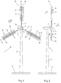
- a wind turbine 1 is shown, the tower 2, which is anchored with its lower end in the bottom 3 is.
- a hub 4 is rotatably arranged that their axis of rotation 5 horizontal and parallel to a wind direction 6 runs.
- radial three carriers 7, which are tangentially spaced and one below the other have an angle of 120 °.
- On the hub 4 opposite end of each carrier 7 is a longitudinal axis 15 rotor blades 8 arranged.
- Each rotor blade 8 has a lattice profile 9 and each of the lattice profiles 9 longitudinal struts 10 and cross struts 11.
- the extend Longitudinal struts are approximately radial, while the transverse struts are tangential run to the axis of rotation 5.
- the grid profile 9 has a main extension plane 12 with a surface normal. The surface normal runs parallel to the axis of rotation 5.
- the Flow which is due to the angle of attack from the negative pressure side the longitudinal strut 10 against which flow flows comes in Contact with the flow on the overpressure side of the next Longitudinal strut 10 and from this in the direction of the first longitudinal strut 10 steered back. In this way the flow will stop on the exposed longitudinal strut 10 through the adjacent longitudinal strut 10 prevents and buoyancy towards the vacuum side generated to a rotation of the hub 4 about the axis of rotation 5 leads according to the direction of rotation 16.
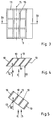
- Fig. 3 is a section of the lattice profile 9 of the upper Rotor wing 8 shown.
- the longitudinal struts 10 are below the angle of attack with respect to the axis of rotation 5 ( Figures 1 and 2) arranged. This can be seen from the fact that in the right Area of the figure, the outer longitudinal strut 10 from the side is observable. In the other longitudinal struts 10 fall Trailing edges of a longitudinal strut 10 with the leading edges of the each arranged to the right of the longitudinal strut 10, so that the rear edges are not visible.
- FIG. 4 shows the section according to IV-IV in FIG. 3. It the angle of attack 14 in relation to the wind direction 6 can be seen, the longitudinal struts 10 with respect to the surface normal 13 the main plane of extent of the lattice profile 9 in the angle of attack 14 are arranged. This means that the longitudinal struts 10 in the grid profile 9 already during manufacture or assembly this angle of attack 14 were used in the lattice profile 9.
- FIG. 5 shows a section corresponding to FIG. 4, where the surface normal 13 of the main extension plane of the Grid profile 9 in the angle of attack 14 with respect to the axis of rotation 5 is arranged. This means that the entire rotor blade with the lattice profile around the longitudinal axis for implementation of the angle of attack 14 has been pivoted. The angle of attack 14 is therefore not already in the manufacture or assembly of the Mesh profiles 9, but only during assembly or adjustment the rotor blade on the hub has been taken into account.
- the wind turbine 1 with the lattice profile 9 is in shown a second embodiment.
- FIG. 7 shows part of the lattice profile rotated about the longitudinal axis 15 9 of the angular power plant 1 according to FIG. 6. The means that the entire rotor blade is rotated by the angle of attack was installed.
- Fig. 8 the angular force system 1 with two arcuate sections Rotor blades 8 shown.
- the run in each case Cross struts 11 between two carriers 7 concentrically around the Rotation axis 5, while the longitudinal struts 10 are radial to the Extend axis of rotation 5. So all buoyancy generating Longitudinal struts 10 the same distance from the axis of rotation 5 on. This has the advantage that all the longitudinal struts 10 have the same relative speed with respect to the hub 4.
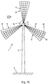
- Fig. 10 the wind turbine 1 with three fan-shaped Rotor blades 8 shown.
- the lattice profiles extend 9 to the hub 4, i.e. they are not carriers intended.
- the cross struts 11 are concentric about the Rotation axis 5 and the longitudinal struts 10 radially to the Rotation axis 5.
- the wind turbine 1 is a continuous rectangular rotor blades 8 shown.
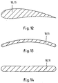
- FIGS. 12 to 14 show possible embodiments of the Struts 10, 11 shown.
- 12 shows aerodynamically profiled struts 10, 11, which are particularly good for generating Buoyancy are suitable.
- the arched struts 10, 11 in FIG. 13 are cheaper to manufacture, but still have good ones aerodynamic properties.
- 14 are struts 10, 11 rectangular cross-section with rounded edges, which is particularly good for use in a lattice profile are suitable because they are sufficiently aerodynamic Properties particularly easy and inexpensive to manufacture are.
Landscapes
- Engineering & Computer Science (AREA)
- Physics & Mathematics (AREA)
- Fluid Mechanics (AREA)
- Life Sciences & Earth Sciences (AREA)
- Sustainable Development (AREA)
- Sustainable Energy (AREA)
- Chemical & Material Sciences (AREA)
- Combustion & Propulsion (AREA)
- Mechanical Engineering (AREA)
- General Engineering & Computer Science (AREA)
- Wind Motors (AREA)
Abstract
Description
- Fig. 1
- eine Vorderansicht einer Windkraftanlage in einer ersten Ausführungsform,
- Fig. 2
- eine Seitenansicht der Windkraftanlage gemäß Figur 1,
- Fig. 3
- eine Detailansicht eines Gitterprofils der Windkraftanlage gemäß Figur 1,
- Fig. 4
- einen Schnitt durch das Gitterprofil der Windkraftanlage gemäß Figur 1 entlang der Linie IV-IV in Fig. 3,
- Fig. 5
- eine Figur 4 entsprechende Schnittansicht eines Gitterprofils bei einer alternativen Anordnung von Längsstreben,
- Fig. 6
- eine Vorderansicht einer zweiten Ausführungsform der Windkraftanlage,
- Fig. 7
- eine Detailansicht eines Gitterprofils der Windkraftanlage gemäß Figur 6,
- Fig. 8
- eine Vorderansicht der Windkraftanlage in einer dritten Ausführungsform,
- Fig. 9
- eine Detailansicht eines Gitterprofils der Windkraftanlage gemäß Figur 8,
- Fig. 10
- eine Vorderansicht einer weiteren Ausführungsform der Windkraftanlage,
- Fig. 11
- eine Vorderansicht einer weiteren Ausführungsform der Windkraftanlage,
- Fig. 12
- eine Schnittansicht einer aerodynamisch profilierten Strebe eines Gitterprofils,
- Fig. 13
- eine Schnittansicht einer gewölbten Strebe eines Gitterprofils, und
- Fig. 14
- eine Schnittansicht einer Strebe eines Gitterprofils mit rechteckigem Querschnitt und abgerundeten Kanten.
- 1 -
- Windkraftanlage
- 2 -
- Turm
- 3 -
- Boden
- 4 -
- Nabe
- 5 -
- Rotationsachse
- 6 -
- Windrichtung
- 7 -
- Träger
- 8 -
- Rotorflügel
- 9 -
- Gitterprofil
- 10 -
- Längsstrebe
- 11 -
- Querstrebe
- 12 -
- Haupterstreckungsebene
- 13 -
- Flächennormale
- 14 -
- Anstellwinkel
- 15 -
- Längsachse
- 16 -
- Drehrichtung
Claims (10)
- Windkraftanlage in Schnelläuferausführung, mit einem Turm, mit einer am oberen Ende des Turms angeordneten und um eine horizontal verlaufende Rotationsachse drehbaren Nabe und mit maximal vier sich von der Nabe radial erstreckenden und tangential beabstandeten luftangeströmten Rotorflügeln zur Erzeugung von Auftrieb und daraus resultierender Drehung der Nabe, dadurch gekennzeichnet, daß die Rotorflügel (8) jeweils ein luftdurchströmtes Gitterprofil (9) zur Erzeugung des Auftriebs aufweisen.
- Windkraftanlage nach Anspruch 1, dadurch gekennzeichnet, daß das Gitterprofil (9) sich in Bezug auf die Rotationsachse (5) radial erstreckende Längsstreben (10) und sich in Bezug auf die Rotationsachse (5) tangential erstreckende Querstreben (11) aufweist.
- Windkraftanlage nach Anspruch 2, dadurch gekennzeichnet, daß das Gitterprofil (9) kreisbogenabschnittförmig ausgebildet ist.
- Windkraftanlage nach Anspruch 2 oder 3, dadurch gekennzeichnet, daß die Längsstreben (10) unter einem Anstellwinkel (14) von 30° ± 5° gegenüber der Rotationsachse (5) angeordnet sind.
- Windkraftanlage nach Anspruch 4, dadurch gekennzeichnet, daß die Längsstreben (10) gegenüber einer Flächennormalen (13) der Haupterstreckungsebene (12) des Gitterprofils (9) in dem Anstellwinkel (14) von 30° ± 5° angeordnet sind.
- Windkraftanlage nach Anspruch 1, dadurch gekennzeichnet, daß das Gitterprofil (9) Streben (10, 11) aufweist, die zueinander in einem Winkel von 90° so angeordnet sind, daß gedachte Diagonalen zwischen den Verbindungsstellen der Streben (10, 11) radial und tangential zu der Rotationsachse (5) verlaufen.
- Windkraftanlage nach Anspruch 4, dieser rückbezogen auf Anspruch 2, oder nach Anspruch 6, dadurch gekennzeichnet, daß die Flächennormalen (13) der Haupterstreckungsebene (12) des Gitterprofils (9) in dem Anstellwinkel (14) von 30° ± 5° gegenüber der Rotationsachse (5) verlaufen.
- Windkraftanlage nach einem der Ansprüche 1 bis 7, dadurch gekennzeichnet, daß das Gitterprofil (9) Streben (10, 11) rechteckigen Querschnitts mit abgerundeten Kanten aufweist.
- Windkraftanlage nach einem der Ansprüche 1 bis 7, dadurch gekennzeichnet, daß das Gitterprofil (9) gewölbte Streben (10, 11) aufweist.
- Windkraftanlage nach einem der Ansprüche 1 bis 7, dadurch gekennzeichnet, daß das Gitterprofil (9) aerodynamisch profilierte Streben (10, 11) aufweist.
Applications Claiming Priority (2)
| Application Number | Priority Date | Filing Date | Title |
|---|---|---|---|
| DE19807193 | 1998-02-20 | ||
| DE19807193A DE19807193C1 (de) | 1998-02-20 | 1998-02-20 | Windkraftanlage in Schnelläuferausführung |
Publications (2)
| Publication Number | Publication Date |
|---|---|
| EP0937893A2 true EP0937893A2 (de) | 1999-08-25 |
| EP0937893A3 EP0937893A3 (de) | 2001-10-04 |
Family
ID=7858425
Family Applications (1)
| Application Number | Title | Priority Date | Filing Date |
|---|---|---|---|
| EP99100991A Withdrawn EP0937893A3 (de) | 1998-02-20 | 1999-01-21 | Rotorblatt für Windkraftanlagen |
Country Status (2)
| Country | Link |
|---|---|
| EP (1) | EP0937893A3 (de) |
| DE (1) | DE19807193C1 (de) |
Cited By (4)
| Publication number | Priority date | Publication date | Assignee | Title |
|---|---|---|---|---|
| RU2246030C2 (ru) * | 2002-11-20 | 2005-02-10 | Таегян Микаел Матеосович | Лопастная крыльчатка ветроэнергетического устройства |
| DE102004053498A1 (de) * | 2004-10-28 | 2006-05-04 | Baumann, Karl, Dr. | Rotorflügel für Windkraftmaschinen |
| ES2263389A1 (es) * | 2005-06-03 | 2006-12-01 | Esdras Automaticas, S.L. | Estructura de subalabes para reduccion del peso de las palas en turbinas eolicas. |
| US12123391B2 (en) | 2023-01-10 | 2024-10-22 | United Arab Emirates University | Wind turbine blade having air passage with air cleaning member |
Families Citing this family (1)
| Publication number | Priority date | Publication date | Assignee | Title |
|---|---|---|---|---|
| SK892007A3 (sk) * | 2007-06-26 | 2009-01-07 | Alexander Kaliský | Sekvenčné krídlo |
Family Cites Families (7)
| Publication number | Priority date | Publication date | Assignee | Title |
|---|---|---|---|---|
| NL24753C (de) * | ||||
| FR636615A (de) * | 1927-06-27 | 1928-04-13 | ||
| US4081221A (en) * | 1976-12-17 | 1978-03-28 | United Technologies Corporation | Tripod bladed wind turbine |
| DE2909781A1 (de) * | 1979-03-13 | 1980-09-25 | Karlheinz Ohlberg | Fluegelrotor, insbesondere fuer windmotoren (windkraftwerke) mit in mindestens 2 konzentrisch aufgeteilte kreisringflaechen |
| FR2575790A3 (fr) * | 1985-01-08 | 1986-07-11 | Tournier Pierre | Roue d'eolienne |
| DE3715265A1 (de) * | 1987-05-08 | 1988-11-24 | Imris Pavel | Windturbine |
| DE8803598U1 (de) * | 1988-03-17 | 1989-04-20 | Seel, Gerd, 7519 Walzbachtal | Einrichtung zur Verminderung des induzierten Widerstandes an Rotorblättern von Windkraftanlagen |
-
1998
- 1998-02-20 DE DE19807193A patent/DE19807193C1/de not_active Expired - Fee Related
-
1999
- 1999-01-21 EP EP99100991A patent/EP0937893A3/de not_active Withdrawn
Non-Patent Citations (1)
| Title |
|---|
| ELEKTROTECHNIK: "Windenergienutzung-Eine übersich", vol. 6, 1988, pages: 40 |
Cited By (5)
| Publication number | Priority date | Publication date | Assignee | Title |
|---|---|---|---|---|
| RU2246030C2 (ru) * | 2002-11-20 | 2005-02-10 | Таегян Микаел Матеосович | Лопастная крыльчатка ветроэнергетического устройства |
| DE102004053498A1 (de) * | 2004-10-28 | 2006-05-04 | Baumann, Karl, Dr. | Rotorflügel für Windkraftmaschinen |
| ES2263389A1 (es) * | 2005-06-03 | 2006-12-01 | Esdras Automaticas, S.L. | Estructura de subalabes para reduccion del peso de las palas en turbinas eolicas. |
| WO2006128940A1 (es) * | 2005-06-03 | 2006-12-07 | Esdras Automatica, S.L. | Estructura de subalabes para reduccion del peso de las palas en turbinas eolicas |
| US12123391B2 (en) | 2023-01-10 | 2024-10-22 | United Arab Emirates University | Wind turbine blade having air passage with air cleaning member |
Also Published As
| Publication number | Publication date |
|---|---|
| DE19807193C1 (de) | 1999-05-27 |
| EP0937893A3 (de) | 2001-10-04 |
Similar Documents
| Publication | Publication Date | Title |
|---|---|---|
| EP1514023B1 (de) | Windenergieanlage | |
| EP2273101B1 (de) | Verfahren zur montage von rotorblättern einer windenergieanlage | |
| EP0364020B1 (de) | Windgetriebener Rotor | |
| EP2469078B1 (de) | Windkraft-Hybridrotor | |
| EP2280163B1 (de) | Windenergieanlage sowie Rotorblatt für eine Windenergieanlage | |
| EP1002949A2 (de) | Windturbine mit senkrechter Drehachse | |
| EP3755899B1 (de) | Rotorblatt einer windenergieanlage mit einer splitterplatte | |
| EP2715117A1 (de) | Rotor mit einem gekrümmten rotorblatt für eine windkraftanlage | |
| WO2001048377A1 (de) | Rotorblatt für eine windenergieanlage | |
| DE19807193C1 (de) | Windkraftanlage in Schnelläuferausführung | |
| AT505351B1 (de) | Windrad | |
| DE4030559C2 (de) | ||
| DE102012107250B4 (de) | Rotor einer vertikalachsigen Windkraftanlage | |
| EP1387954B1 (de) | Vertikalachs-windturbine | |
| DE3505489A1 (de) | Fluegel fuer eine windkraftanlage | |
| EP4224010B1 (de) | Rotor für eine vertikale windkraftanlage | |
| WO2020043722A1 (de) | Rotorblatt, windenergieanlage und verfahren zum optimieren einer windenergieanlage | |
| DE102008054126A1 (de) | Rotor für eine Windkraftanlage | |
| DE202008005724U1 (de) | Axial durchströmte Windturbine | |
| EP3969741B1 (de) | Rotorblatt und windenergieanlage | |
| EP2636892A2 (de) | Windkraftanlage und Verfahren zum Erzeugen von rotatorischer Energie durch Wind | |
| CH700422B1 (de) | Axial durchströmte Windturbine. | |
| DE9414258U1 (de) | Strömungskraftmaschine | |
| DE29721501U1 (de) | Rotor für eine Windkraftanlage | |
| DE102011017373A1 (de) | Windkraftanlage |
Legal Events
| Date | Code | Title | Description |
|---|---|---|---|
| PUAI | Public reference made under article 153(3) epc to a published international application that has entered the european phase |
Free format text: ORIGINAL CODE: 0009012 |
|
| AK | Designated contracting states |
Kind code of ref document: A2 Designated state(s): AT BE CH CY DE DK ES FI FR GB GR IE IT LI LU MC NL PT SE Kind code of ref document: A2 Designated state(s): GB NL |
|
| AX | Request for extension of the european patent |
Free format text: AL;LT;LV;MK;RO;SI |
|
| RIN1 | Information on inventor provided before grant (corrected) |
Inventor name: WEDEMEYER, ERICH, DR. RER. NAT. Inventor name: HEDDERGOTT, ALFRED, DIPL.-ING. Inventor name: PSOLLA-BRESS, HARTMUT, DIPL.-ING. |
|
| PUAL | Search report despatched |
Free format text: ORIGINAL CODE: 0009013 |
|
| AK | Designated contracting states |
Kind code of ref document: A3 Designated state(s): AT BE CH CY DE DK ES FI FR GB GR IE IT LI LU MC NL PT SE |
|
| AX | Request for extension of the european patent |
Free format text: AL;LT;LV;MK;RO;SI |
|
| 17P | Request for examination filed |
Effective date: 20020130 |
|
| AKX | Designation fees paid |
Free format text: GB NL |
|
| REG | Reference to a national code |
Ref country code: DE Ref legal event code: 8566 |
|
| RAP1 | Party data changed (applicant data changed or rights of an application transferred) |
Owner name: DEUTSCHES ZENTRUM FUER LUFT- UND RAUMFAHRT E.V. |
|
| STAA | Information on the status of an ep patent application or granted ep patent |
Free format text: STATUS: THE APPLICATION IS DEEMED TO BE WITHDRAWN |
|
| 18D | Application deemed to be withdrawn |
Effective date: 20080801 |