EP0937293B1 - Indicateur presentant une importante discontinuite due a l'effet de barkhausen - Google Patents
Indicateur presentant une importante discontinuite due a l'effet de barkhausen Download PDFInfo
- Publication number
- EP0937293B1 EP0937293B1 EP97940963A EP97940963A EP0937293B1 EP 0937293 B1 EP0937293 B1 EP 0937293B1 EP 97940963 A EP97940963 A EP 97940963A EP 97940963 A EP97940963 A EP 97940963A EP 0937293 B1 EP0937293 B1 EP 0937293B1
- Authority
- EP
- European Patent Office
- Prior art keywords
- wire
- marker
- annealing
- magnetic
- tension
- Prior art date
- Legal status (The legal status is an assumption and is not a legal conclusion. Google has not performed a legal analysis and makes no representation as to the accuracy of the status listed.)
- Expired - Lifetime
Links
- 239000003550 marker Substances 0.000 title claims abstract description 50
- 238000000137 annealing Methods 0.000 claims description 32
- 238000000034 method Methods 0.000 claims description 22
- 239000000696 magnetic material Substances 0.000 claims description 14
- 229910017052 cobalt Inorganic materials 0.000 claims description 9
- 239000010941 cobalt Substances 0.000 claims description 9
- GUTLYIVDDKVIGB-UHFFFAOYSA-N cobalt atom Chemical compound [Co] GUTLYIVDDKVIGB-UHFFFAOYSA-N 0.000 claims description 9
- 239000000203 mixture Substances 0.000 claims description 8
- 229910001092 metal group alloy Inorganic materials 0.000 claims description 7
- 230000010287 polarization Effects 0.000 claims description 6
- 238000005266 casting Methods 0.000 claims description 5
- 239000005300 metallic glass Substances 0.000 claims description 4
- 230000001172 regenerating effect Effects 0.000 claims description 3
- 230000000717 retained effect Effects 0.000 claims description 2
- 229910000808 amorphous metal alloy Inorganic materials 0.000 claims 1
- 238000005491 wire drawing Methods 0.000 claims 1
- 229910000531 Co alloy Inorganic materials 0.000 abstract description 5
- 239000000463 material Substances 0.000 description 25
- 230000008569 process Effects 0.000 description 11
- 238000001514 detection method Methods 0.000 description 4
- 238000010586 diagram Methods 0.000 description 4
- 230000005415 magnetization Effects 0.000 description 4
- 229910045601 alloy Inorganic materials 0.000 description 3
- 239000000956 alloy Substances 0.000 description 3
- XEEYBQQBJWHFJM-UHFFFAOYSA-N iron Substances [Fe] XEEYBQQBJWHFJM-UHFFFAOYSA-N 0.000 description 3
- RVTZCBVAJQQJTK-UHFFFAOYSA-N oxygen(2-);zirconium(4+) Chemical compound [O-2].[O-2].[Zr+4] RVTZCBVAJQQJTK-UHFFFAOYSA-N 0.000 description 3
- 230000004044 response Effects 0.000 description 3
- 238000013459 approach Methods 0.000 description 2
- 230000000694 effects Effects 0.000 description 2
- 239000000758 substrate Substances 0.000 description 2
- 230000005330 Barkhausen effect Effects 0.000 description 1
- 239000004820 Pressure-sensitive adhesive Substances 0.000 description 1
- 230000009471 action Effects 0.000 description 1
- 230000008859 change Effects 0.000 description 1
- 238000007796 conventional method Methods 0.000 description 1
- 238000002425 crystallisation Methods 0.000 description 1
- 230000008025 crystallization Effects 0.000 description 1
- 230000003247 decreasing effect Effects 0.000 description 1
- 238000013461 design Methods 0.000 description 1
- 230000004907 flux Effects 0.000 description 1
- 238000010438 heat treatment Methods 0.000 description 1
- 229910052742 iron Inorganic materials 0.000 description 1
- 238000012545 processing Methods 0.000 description 1
- 238000010791 quenching Methods 0.000 description 1
- 230000000171 quenching effect Effects 0.000 description 1
- 230000009467 reduction Effects 0.000 description 1
- 230000001105 regulatory effect Effects 0.000 description 1
- 230000008054 signal transmission Effects 0.000 description 1
- XLYOFNOQVPJJNP-UHFFFAOYSA-N water Substances O XLYOFNOQVPJJNP-UHFFFAOYSA-N 0.000 description 1
Images


Classifications
-
- G—PHYSICS
- G08—SIGNALLING
- G08B—SIGNALLING OR CALLING SYSTEMS; ORDER TELEGRAPHS; ALARM SYSTEMS
- G08B13/00—Burglar, theft or intruder alarms
- G08B13/22—Electrical actuation
- G08B13/24—Electrical actuation by interference with electromagnetic field distribution
- G08B13/2402—Electronic Article Surveillance [EAS], i.e. systems using tags for detecting removal of a tagged item from a secure area, e.g. tags for detecting shoplifting
- G08B13/2405—Electronic Article Surveillance [EAS], i.e. systems using tags for detecting removal of a tagged item from a secure area, e.g. tags for detecting shoplifting characterised by the tag technology used
- G08B13/2408—Electronic Article Surveillance [EAS], i.e. systems using tags for detecting removal of a tagged item from a secure area, e.g. tags for detecting shoplifting characterised by the tag technology used using ferromagnetic tags
-
- G—PHYSICS
- G08—SIGNALLING
- G08B—SIGNALLING OR CALLING SYSTEMS; ORDER TELEGRAPHS; ALARM SYSTEMS
- G08B13/00—Burglar, theft or intruder alarms
- G08B13/22—Electrical actuation
- G08B13/24—Electrical actuation by interference with electromagnetic field distribution
- G08B13/2402—Electronic Article Surveillance [EAS], i.e. systems using tags for detecting removal of a tagged item from a secure area, e.g. tags for detecting shoplifting
- G08B13/2428—Tag details
- G08B13/2437—Tag layered structure, processes for making layered tags
- G08B13/2442—Tag materials and material properties thereof, e.g. magnetic material details
-
- H—ELECTRICITY
- H01—ELECTRIC ELEMENTS
- H01F—MAGNETS; INDUCTANCES; TRANSFORMERS; SELECTION OF MATERIALS FOR THEIR MAGNETIC PROPERTIES
- H01F1/00—Magnets or magnetic bodies characterised by the magnetic materials therefor; Selection of materials for their magnetic properties
- H01F1/01—Magnets or magnetic bodies characterised by the magnetic materials therefor; Selection of materials for their magnetic properties of inorganic materials
- H01F1/03—Magnets or magnetic bodies characterised by the magnetic materials therefor; Selection of materials for their magnetic properties of inorganic materials characterised by their coercivity
- H01F1/12—Magnets or magnetic bodies characterised by the magnetic materials therefor; Selection of materials for their magnetic properties of inorganic materials characterised by their coercivity of soft-magnetic materials
- H01F1/14—Magnets or magnetic bodies characterised by the magnetic materials therefor; Selection of materials for their magnetic properties of inorganic materials characterised by their coercivity of soft-magnetic materials metals or alloys
- H01F1/147—Alloys characterised by their composition
- H01F1/153—Amorphous metallic alloys, e.g. glassy metals
- H01F1/15391—Elongated structures, e.g. wires
Definitions
- This invention relates to magnetic markers for use in electronic article surveillance (EAS) systems and to methods, apparatus and systems for using and making such markers.
- EAS electronic article surveillance
- patent no. 4,660,025, and of related patent no. 4,686,516, is incorporated herein by reference.
- Fig. 1 illustrates a hysteresis loop characteristic of the marker disclosed in the '025 patent.
- Indicated at 20 and 22 in Fig. 1 are large and substantially instantaneous reversals in magnetic polarity exhibited by the magnetic material disclosed in the '025 patent. These reversals are referred to as "Barkhausen discontinuities" and occur at a magnetizing field threshold level having the magnitude H*.
- the marker will exhibit a very sharp signal spike, rich in high harmonic frequencies that are readily detectable by the EAS system.
- the '025 patent discloses, as a particular example of a suitable magnetic material, an amorphous wire segment having the composition Fe 81 Si 4 B 14 C 1 , where the percentages are in atomic percent.
- the threshold for the material was less than 0.6 Oe.
- this particular material generated a sharp spike even when the incident interrogation field had a peak amplitude of 0.6 Oe.
- the actual strength of the incident interrogation field signal experienced by a marker in an interrogation zone of an EAS system may vary substantially from place to place within the zone.
- the field strength ranges from a maximum at locations adjacent to the interrogation signal transmission antenna or antennas, to much lower levels at points in the interrogation zone that are relatively distant from the antenna (s) . If a marker of the type disclosed in the '025 patent is exposed to an interrogation signal that has an amplitude lower than the threshold level H T of the hysteresis loop for the material, then the desired sharp spike output is not generated.
- magnetic materials having threshold levels as low as about 0.04 Oe are known, the lowest reported threshold for wire segments actually employed in EAS markers is about 0.08 Oe.
- the incident interrogation field signal level present at some points in the interrogation zone may be below the threshold, so that the Barkhausen switch does not occur and the marker is not detectable when at such points in the zone.
- the dimensions of the interrogation zone may be reduced, again to ensure that the interrogation signal level exceeds the threshold level throughout the zone.
- this approach may not be acceptable to operators of the systems and their customers, since reducing the interrogation zone can be accomplished only by narrowing the exits from premises at which the EAS system is employed.
- a marker for use in an article surveillance system in which an alternating magnetic field is established in a surveillance region and an alarm is activated when a predetermined perturbation to the field is detected
- the marker including a body of magnetic material with retained stress and having a magnetic hysteresis loop with a large Barkhausen discontinuity such that exposure of the body to an external magnetic field, whose field strength in the direction opposing the magnetic polarization of the body exceeds a predetermined threshold value, results in regenerative reversal of the magnetic polarization, and structure for securing the body to be maintained under surveillance, with the predetermined threshold level being less than 0.04 Oe.
- the predetermined threshold level is substantially 0.02 Oe.
- the magnetic body for such a marker is formed by casting a metal alloy to form an amorphous metal wire, die-drawing the wire to reduce a diameter thereof, and annealing the drawn wire while applying longitudinal tension to the drawn wire, where the metal alloy exhibits negative magnetostriction.
- the alloy is cobalt-based, including more than 70% cobalt by atomic percent.
- the process for forming the magnetic body includes casting a negative-magnetostrictive metal alloy to form an amorphous metal wire, processing the wire to form longitudinal compressive stress in the wire, and annealing the processed wire to relieve some of the longitudinal compressive stress.
- the effective switching threshold at which the Barkhausen discontinuities occur is reduced to approximately one-half of the lowest previously-known threshold level.
- the resulting markers can be detected with substantially greater reliability, even when present at a point in an interrogation zone where the incident interrogation signal strength is at a minimum level.
- the present invention is a remarkable departure from the prior art in that it has not previously been known to tension-anneal a cobalt-based wire to produce a wire segment which exhibits a Barkhausen discontinuity.
- positive magnetostrictive materials such as iron-based amorphous wire
- cobalt wire exhibits negative magnetostriction, and tension-annealing therefore tends to eliminate longitudinal anisotropy.
- the prior art has never proposed to tension-anneal cobalt wire when a Barkhausen discontinuity is desired, since the Barkhausen effect is eliminated if the longitudinal anisotropy is destroyed.
- Fig. 2 provides an overview, in flow-diagram form, of a process carried out in accordance with the invention to produce EAS markers which exhibit a large Barkhausen discontinuity at a very low field threshold level.
- Fig. 2 begins with a first step, represented by block 30, in which a cobalt-based alloy is cast to form an amorphous wire.
- a conventional casting process such as in-rotating-water quenching may be employed.
- step 32 at which the cast wire is cold drawn to reduce the diameter thereof.
- the die-drawing step produces longitudinal compressive stress in the wire, which forms a longitudinal anisotropy and also tends to elevate the threshold level for resulting marker elements.
- step 34 at which the die-drawn wire is annealed while applying longitudinal tension to the wire.
- This annealing step if performed with suitable parameters, relieves and redistributes some of the compressive stress produced by the die-drawing, and greatly reduces the threshold level at which the Barkhausen discontinuity occurs, while preserving a substantial output signal level.
- step 36 is performed, in which the annealed wire is cut into discrete wire segments suitable for inclusion in a marker.
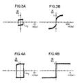
- FIG. 3(a) and 3(b) show signal traces obtained by driving a 70 mm length of the die-drawn wire with fields having respective peak amplitudes of 2 Oe and about 120 Oe.
- the abscissa axis corresponds to the incident magnetic field applied along the length of the wire segment
- the ordinate axis corresponds to the resulting normalized magnetization level (magnetization level divided by magnetization at saturation (M s )).
- M s magnetization level divided by magnetization at saturation
- a large Barkhausen discontinuity occurs at a threshold level H* of about 2 Oe.
- the die-drawn material exhibits a squareness ratio (remanent magnetization at zero applied field, divided by M s ) of about 0.35.
- the die-drawn wire described just above is annealed (before cutting) for one hour at 440°C while applying longitudinal tension to the wire.
- the longitudinal tension may be applied by a conventional technique such as suspending a body of the desired mass from one end of the wire and holding the other end of the wire fixed.
- a preferred tension is 25 kg/mm 2 .
- Fig. 4(a) shows the signal trace produced with a low-level driving field
- Fig. 4(b) shows the signal trace produced with a high-level driving field.
- the resulting wire segment has a switching threshold H* of slightly more than 0.02 Oe. This represents a reduction in the threshold level by a factor of two in comparison with the lowest levels of H* that have previously been reported. In addition, a squareness ratio of 0.95 was achieved, which provides for an ample output signal level. It is believed that previously reported levels of H* in the range of 0.04 or 0.045 De have been achieved only with a substantially lower squareness ratio and by processes that may not be suitable for large-scale implementation.
- the amorphous cobalt wire, as cast, has a threshold of about 0.05 Oe, but exhibits a very low output amplitude which is undesirable for use in a marker in its as-cast form.
- the subsequent die-drawing generates a large longitudinal compressive stress in the core of the wire.
- the compressive stress creates a longitudinal anisotropy in the wire, due to the negative magnetostriction exhibited by the cobalt material.
- the induced longitudinal anisotropy increases the threshold level (as shown in Fig.
- the subsequent longitudinal-tension annealing if performed with suitable parameters, is believed to relieve and redistribute some of the longitudinal compressive stress, so that the desired low threshold level for the Barkhausen discontinuity is obtained, with a suitably high output level.
- Figs. 5(a) and (b) are signal traces representing the hysteresis loop of a discrete segment of a wire material formed when the same continuous die-drawn cobalt-alloy wire is annealed for the same time period and with the same longitudinal tension as in Example 1, but at a temperature of 380°C.
- the trace of Fig. 5(a) shows the hysteresis loop when a low-level driving signal is used
- the trace of Fig. 5(b) shows the hysteresis loop resulting from a higher-level driving field.
- the switching (Barkhausen discontinuity) threshold is about 0.1 Oe, roughly five times higher than the threshold of the material produced in Example 1. Further, the squareness ratio of the material of this Example 2 is about .6, substantially less than the squareness ratio for the Example 1 material. It is believed that the annealing temperature of 380° was too low to achieve sufficient relief and redistribution of the longitudinal compressive stress.
- Fig. 6 shows a signal trace indicative of the hysteresis loop obtained by applying the same annealing process to the die-drawn cobalt-alloy wire, but at a temperature of 520°C. It is believed that the material was crystallized, in this annealing process, resulting in the indicated very low output signal level.
- Fig. 7 shows a signal trace indicating the hysteresis loop for the same material as in Example 1, but with a longitudinal tension of 75 kg/mm 2 applied during annealing. The annealing time and temperature were unchanged from Example 1. It is seen that the trace in Fig. 7 shows a shear hysteresis loop, which lacks the desired Barkhausen discontinuity. In view of the negative magnetostriction exhibited by the cobalt based material, it is believed that the large longitudinal tension applied in this Example results in a circumferential anisotropy, which produces the shear hysteresis loop shown in Fig. 7.
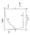
- Fig. 8 illustrates how variations in the amount of longitudinal tension applied during the annealing step affect the squareness ratio and threshold levels for the resulting wire segments.
- the applied longitudinal tension was varied within a range from 0 to 25 kg/mm 2 , while employing the same material and the same time and temperature parameters as in Example 1.
- Curve 38 in Fig. 8 graphs the resulting Barkhausen discontinuity threshold levels as a function of the applied longitudinal tension
- curve 40 indicates the resulting squareness level as a function of applied longitudinal tension. It will be observed that the resulting threshold level remains essentially unchanged, and at a level below 0.03 Oe, over the range of tensions 2 kg/mm 2 to 25 kg/mm 2 . If the tension is omitted, the threshold remains well above 0.1 Oe. Meanwhile, the squareness ratio increases from less than 0.6 to well over 0.9 as the tension is increased from 2 kg/mm 2 to 25 kg/mm 2 .
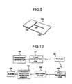
- Fig. 9 shows a marker 120 constructed using the low-threshold magnetic material produced in accordance with the invention.
- the marker 120 includes a wire segment 123, like that produced in Example 1.
- the wire segment 123 is sandwiched between a substrate 121 and an overlayer 122.
- the undersurface of the substrate 121 may be coated with a suitable pressure sensitive adhesive to secure the marker 120 to an article which is to be maintained under surveillance. Alternatively, other known arrangements may be employed to secure the marker to the article.
- a system used to detect the presence of the marker 120 is shown in block diagram form in Fig. 10.
- the system includes a frequency generator block 160 and a coil 161 for radiating the interrogation signal.
- a receiving coil 162 Also included in the system are a receiving coil 162, a high pass filter 163, a frequency selection/detection circuit 164, and an alarm device 165.
- the frequency generator 160 drives the field generating coil 161 to radiate an interrogation signal field in the interrogation zone.
- the field receiving coil 162 drives the field generating coil 161 to radiate an interrogation signal field in the interrogation zone.
- the output of the receiving coil 162 is passed through the high pass filter 163, which has a suitable cutoff frequency to provide high harmonic frequencies of interest to the selection/detection circuit 164.
- the selection/detection circuit 164 is arranged so that, when the high harmonic frequencies are present at a sufficient amplitude, an output is provided to activate the alarm device 165.
- the low threshold and high output level characteristics of the marker formed in accordance with the invention reliable detection of the marker can be achieved, even if the marker passes through portions of the interrogation zone at which the interrogation signal is at a low level. It therefore is not necessary to increase the amplitude of the interrogation field provided by the generating coil 161, nor to reduce the size of the interrogation zone, in order to achieve increased reliability in detecting the marker.
- markers produced in accordance with the invention may be deactivated by crystallizing some or all of the bulk of the wire 123, as taught in the above-referenced patent no. 4,686,516.
Landscapes
- Physics & Mathematics (AREA)
- Engineering & Computer Science (AREA)
- Electromagnetism (AREA)
- Automation & Control Theory (AREA)
- Computer Security & Cryptography (AREA)
- General Physics & Mathematics (AREA)
- Chemical & Material Sciences (AREA)
- Dispersion Chemistry (AREA)
- Power Engineering (AREA)
- Burglar Alarm Systems (AREA)
- Chemical And Physical Treatments For Wood And The Like (AREA)
Abstract
Claims (17)
- Marqueur (120) pour une utilisation dans un système de surveillance d'articles dans lequel un champ magnétique alternatif est établi dans une région de surveillance et une alarme est activée lorsqu'une perturbation prédéterminée dudit champ est détectée, ledit marqueur (120) comprenant un corps en un matériau magnétique avec une contrainte rémanente et ayant une boucle d'hystérésis magnétique avec une grande discontinuité de Barkhausen de sorte qu'une exposition dudit corps à un champ magnétique externe, dont l'intensité de champ dans la direction opposée à la polarisation magnétique dudit corps dépasse une valeur de seuil prédéterminée, résulte en une inversion régénérative de ladite polarisation magnétique, et des moyens pour fixer ledit corps sur un article devant être maintenu sous surveillance, caractérisé en ce que ledit matériau magnétique présente une magnétostriction négative, ledit corps a la forme d'un segment de fil coupé discret en alliage métallique amorphe coulé ayant un diamètre réduit du fait de l'étirage ou du tréfilage du fil et recuit sous une tension longitudinale appliquée au fil tréfilé ou étiré, et ledit niveau de seuil prédéterminé est inférieur à 0,04 Oe.
- Marqueur (120) selon la revendication 1, dans lequel ledit niveau de seuil prédéterminé est inférieur à 0,03 Oe.
- Marqueur (120) selon la revendication 2, dans lequel ledit niveau de seuil prédéterminé est sensiblement de 0,02 Oe.
- Marqueur (120) selon la revendication 1, dans lequel ledit corps comprend une longueur de fil métallique amorphe.
- Marqueur (120) selon la revendication 4, dans lequel ledit fil comprend au moins 70 % de cobalt en pourcentage atomique.
- Marqueur (120) selon la revendication 5, dans lequel la composition métallurgique dudit fil est essentiellement donnée par la formule Co72,5Si12,5B15, dans laquelle les pourcentages sont des pourcentages atomiques.
- Marqueur (120) selon l'une des revendications précédentes, dans lequel ledit recuit est effectué à une température dans la plage de 420°C à 500°C et ladite tension longitudinale est dans la plage de 2 à 25 kg/mm2.
- Marqueur (120) selon la revendication 7, dans lequel ledit tréfilage réduit le diamètre du fil coulé de sensiblement 125 microns à sensiblement 50 microns.
- Marqueur (120) selon la revendication 8, dans lequel :la composition métallurgique dudit alliage métallique est essentiellement donnée par la formule Co72,5Si12,5B15, dans laquelle les pourcentages sont des pourcentages atomiques ; etledit recuit est effectué à une température sensiblement de 440°C et avec l'application de ladite tension longitudinale sensiblement à 25 kg/mm2.
- Procédé de formation d'un matériau magnétique pour une utilisation en tant que marqueur EAS (120) selon la revendication 1, comprenant les étapes consistant à :couler l'alliage métallique afin de former le fil métallique amorphe qui présente une magnétostriction négative ;tréfiler ledit fil afin de réduire son diamètre ;recuire le fil tréfilé tout en appliquant une tension longitudinale au fil tréfilé et couper ledit fil en segments discrets.
- Procédé selon la revendication 10, dans lequel ledit alliage métallique comprend au moins 70 % de cobalt en pourcentage atomique.
- Procédé selon la revendication 11, dans lequel la composition métallurgique dudit alliage métallique est essentiellement donnée par la formule Co72,5Si12,5B15, dans laquelle les pourcentages sont des pourcentages atomiques.
- Procédé selon la revendication 10, dans lequel ladite étape de recuit (34) est effectuée à une température dans la plage de 420°C à 500°C.
- Procédé selon la revendication 13, dans lequel ladite étape de recuit (34) est effectuée à une température sensiblement de 440°C.
- Procédé selon la revendication 10, dans lequel ladite tension appliquée pendant ladite étape de recuit (34) est dans la plage de 2 à 25 kg/mm2.
- Procédé selon la revendication 15, dans lequel ladite tension appliquée pendant ladite étape de recuit (34) est sensiblement de 25 kg/mm2.
- Procédé selon la revendication 10, dans lequel le fil formé par ladite étape de coulée (30) a un diamètre sensiblement de 125 microns et ladite étape de tréfilage (32) réduit le diamètre à sensiblement 50 microns.
Applications Claiming Priority (3)
| Application Number | Priority Date | Filing Date | Title |
|---|---|---|---|
| US745683 | 1996-11-08 | ||
| US08/745,683 US5801630A (en) | 1996-11-08 | 1996-11-08 | Article surveillance magnetic marker having an hysteresis loop with large barkhausen discontinuities at a low field threshold level |
| PCT/US1997/015950 WO1998020467A1 (fr) | 1996-11-08 | 1997-09-09 | Indicateur presentant une importante discontinuite due a l'effet de barkhausen |
Publications (3)
| Publication Number | Publication Date |
|---|---|
| EP0937293A1 EP0937293A1 (fr) | 1999-08-25 |
| EP0937293A4 EP0937293A4 (fr) | 2001-05-09 |
| EP0937293B1 true EP0937293B1 (fr) | 2004-12-08 |
Family
ID=24997792
Family Applications (1)
| Application Number | Title | Priority Date | Filing Date |
|---|---|---|---|
| EP97940963A Expired - Lifetime EP0937293B1 (fr) | 1996-11-08 | 1997-09-09 | Indicateur presentant une importante discontinuite due a l'effet de barkhausen |
Country Status (8)
| Country | Link |
|---|---|
| US (1) | US5801630A (fr) |
| EP (1) | EP0937293B1 (fr) |
| AR (1) | AR013330A1 (fr) |
| AU (1) | AU718853B2 (fr) |
| BR (1) | BR9713337A (fr) |
| CA (1) | CA2271020C (fr) |
| DE (1) | DE69731896T2 (fr) |
| WO (1) | WO1998020467A1 (fr) |
Families Citing this family (25)
| Publication number | Priority date | Publication date | Assignee | Title |
|---|---|---|---|---|
| JPH10222283A (ja) * | 1997-01-31 | 1998-08-21 | Seiko Denshi Kiki Kk | 座標読取装置およびその座標指示器 |
| AU2002301264B2 (en) * | 1997-10-07 | 2005-11-24 | North Carolina State University | Thermal processor measurement using simulated food particles |
| US5932813A (en) * | 1997-10-07 | 1999-08-03 | North Carolina State University | Method and system for residence time measurement of simulated food particles in continuous thermal food processing and simulated food particles for use in same |
| US6023226A (en) * | 1998-01-29 | 2000-02-08 | Sensormatic Electronics Corporation | EAS marker with flux concentrators having magnetic anisotropy oriented transversely to length of active element |
| IL131866A0 (en) * | 1999-09-10 | 2001-03-19 | Advanced Coding Systems Ltd | A glass-coated amorphous magnetic microwire marker for article surveillance |
| US6747559B2 (en) | 1999-09-10 | 2004-06-08 | Advanced Coding Systems Ltd. | Glass-coated amorphous magnetic mircowire marker for article surveillance |
| IL132499A0 (en) | 1999-10-21 | 2001-03-19 | Advanced Coding Systems Ltd | A security system for protecting various items and a method for reading a code pattern |
| EP1281055A4 (fr) * | 2000-03-10 | 2003-05-21 | Univ North Carolina State | Technique et systeme d'evaluation, de validation et de surveillance prudentes pour traitement thermique |
| US6556139B2 (en) | 2000-11-14 | 2003-04-29 | Advanced Coding Systems Ltd. | System for authentication of products and a magnetic tag utilized therein |
| EP1623048B1 (fr) * | 2003-01-28 | 2014-03-19 | North Carolina State University | Procedes, systemes et dispositifs pour evaluer un traitement thermique |
| ES2268964B1 (es) | 2005-04-21 | 2008-04-16 | Micromag 2000, S.L. | "etiqueta magnetica activable/desactivable basada en microhilo magnetico y metodo de obtencion de la misma". |
| WO2008020148A2 (fr) * | 2006-08-17 | 2008-02-21 | Maganetix Ltd | Marqueur magnétique désactivable à double fonction et son procédé de désactivation |
| JP4539699B2 (ja) * | 2007-09-19 | 2010-09-08 | 富士ゼロックス株式会社 | 携行物管理ゲート |
| US9574865B2 (en) | 2010-08-14 | 2017-02-21 | Micro-Epsilon Messtechnik Gmbh & Co. Kg | Method and apparatus for sensing magnetic fields |
| JP5960476B2 (ja) * | 2012-03-30 | 2016-08-02 | 株式会社ケーヒン | 磁気異方性塑性加工品及びその製造方法と、それを用いた電磁装置 |
| US9275529B1 (en) | 2014-06-09 | 2016-03-01 | Tyco Fire And Security Gmbh | Enhanced signal amplitude in acoustic-magnetomechanical EAS marker |
| US9418524B2 (en) | 2014-06-09 | 2016-08-16 | Tyco Fire & Security Gmbh | Enhanced signal amplitude in acoustic-magnetomechanical EAS marker |
| CN106248781A (zh) * | 2016-07-27 | 2016-12-21 | 南京航空航天大学 | 一种基于巴克豪森原理的材料磁特性与应力检测方法 |
| JP6428884B1 (ja) * | 2017-09-11 | 2018-11-28 | 愛知製鋼株式会社 | 磁気センサ用感磁ワイヤおよびその製造方法 |
| GB2582123B (en) * | 2018-01-25 | 2021-04-28 | Endomagnetics Ltd | Systems and methods for detecting magnetic markers for surgical guidance |
| GB2573500B (en) | 2018-03-23 | 2020-11-04 | Endomagnetics Ltd | Magnetic markers for surgical guidance |
| GB2585034A (en) * | 2019-06-25 | 2020-12-30 | Endomagnetics Ltd | Hyperthermia implants and a method and system for heating the implant |
| RU2725755C1 (ru) * | 2020-01-31 | 2020-07-06 | Александр Николаевич Шалыгин | Машиночитаемая идентификационная метка на основе аморфного микропровода для бумажного листового материала на целлюлозной основе |
| GB2595858B (en) * | 2020-06-08 | 2022-06-22 | Endomagnetics Ltd | Systems and methods for detecting magnetic markers for surgical guidance |
| CN116746934B (zh) * | 2023-05-08 | 2025-09-26 | 大连理工大学 | 一种基于钴基非晶线的肌磁测量装置 |
Family Cites Families (11)
| Publication number | Priority date | Publication date | Assignee | Title |
|---|---|---|---|---|
| US3853717A (en) * | 1973-06-29 | 1974-12-10 | Sperry Rand Corp | Plated wire memory |
| US4075618A (en) * | 1976-07-15 | 1978-02-21 | Minnesota Mining And Manufacturing Company | Magnetic asymmetric antipilferage marker |
| JPS5779052A (en) * | 1980-10-16 | 1982-05-18 | Takeshi Masumoto | Production of amorphous metallic filament |
| JPS58173059A (ja) * | 1982-03-03 | 1983-10-11 | Unitika Ltd | 金属細線の製造方法 |
| US4797658A (en) * | 1984-11-26 | 1989-01-10 | Sensormatic Electronics Corporation | Article surveillance marker capable of being deactivated by relieving the retained stress therein and method and system for deactivating the marker |
| US4686516A (en) * | 1984-11-26 | 1987-08-11 | Sensormatic Electronics Corporation | Method, system and apparatus for use in article surveillance |
| US4660025A (en) * | 1984-11-26 | 1987-04-21 | Sensormatic Electronics Corporation | Article surveillance magnetic marker having an hysteresis loop with large Barkhausen discontinuities |
| US4980670A (en) * | 1987-11-04 | 1990-12-25 | Sensormatic Electronics Corporation | Deactivatable E.A.S. marker having a step change in magnetic flux |
| US5029291A (en) * | 1990-04-10 | 1991-07-02 | Knogo Corporation | Electromagnetic sensor element and methods and apparatus for making and using same |
| US5313192A (en) * | 1992-07-02 | 1994-05-17 | Sensormatic Electronics Corp. | Deactivatable/reactivatable magnetic marker having a step change in magnetic flux |
| US5519379A (en) * | 1995-04-10 | 1996-05-21 | Sensormatic Electronics Corporation | Multi-thread re-entrant marker with simultaneous switching |
-
1996
- 1996-11-08 US US08/745,683 patent/US5801630A/en not_active Expired - Lifetime
-
1997
- 1997-09-09 EP EP97940963A patent/EP0937293B1/fr not_active Expired - Lifetime
- 1997-09-09 DE DE69731896T patent/DE69731896T2/de not_active Expired - Lifetime
- 1997-09-09 CA CA002271020A patent/CA2271020C/fr not_active Expired - Fee Related
- 1997-09-09 BR BR9713337-0A patent/BR9713337A/pt unknown
- 1997-09-09 WO PCT/US1997/015950 patent/WO1998020467A1/fr not_active Ceased
- 1997-09-09 AU AU42628/97A patent/AU718853B2/en not_active Ceased
- 1997-11-07 AR ARP970105188A patent/AR013330A1/es unknown
Also Published As
| Publication number | Publication date |
|---|---|
| AU4262897A (en) | 1998-05-29 |
| WO1998020467A1 (fr) | 1998-05-14 |
| CA2271020C (fr) | 2005-04-19 |
| AU718853B2 (en) | 2000-04-20 |
| DE69731896D1 (de) | 2005-01-13 |
| DE69731896T2 (de) | 2005-05-19 |
| US5801630A (en) | 1998-09-01 |
| EP0937293A4 (fr) | 2001-05-09 |
| AR013330A1 (es) | 2000-12-27 |
| EP0937293A1 (fr) | 1999-08-25 |
| BR9713337A (pt) | 2000-05-09 |
| CA2271020A1 (fr) | 1998-05-14 |
Similar Documents
| Publication | Publication Date | Title |
|---|---|---|
| EP0937293B1 (fr) | Indicateur presentant une importante discontinuite due a l'effet de barkhausen | |
| US4660025A (en) | Article surveillance magnetic marker having an hysteresis loop with large Barkhausen discontinuities | |
| EP0820534B1 (fr) | Alliages amorphes vitreux destines a des systemes de surveillance avec indicateurs a resonance mecanique | |
| US4686516A (en) | Method, system and apparatus for use in article surveillance | |
| US4797658A (en) | Article surveillance marker capable of being deactivated by relieving the retained stress therein and method and system for deactivating the marker | |
| EP1145202B1 (fr) | Element magnetostrictif riche en fer presentant une caracteristique optimisee de frequence de resonance dependant du champ de polarisation | |
| JPH0887237A (ja) | 電子物品監視装置用磁気標識及び製造方法 | |
| US6254695B1 (en) | Method employing tension control and lower-cost alloy composition annealing amorphous alloys with shorter annealing time | |
| JPH01150881A (ja) | 不作動化可能な磁気マーカー及びその製造方法及びそれを使用した物品監視システム | |
| US5519379A (en) | Multi-thread re-entrant marker with simultaneous switching | |
| EP0907957B1 (fr) | Alliages de verre metallique pour dispositifs de surveillance a marqueurs a resonance mecanique | |
| EP0820633B1 (fr) | Alliages amorphes vitreux destines a des systemes de surveillance avec indicateurs a resonance mecanique | |
| US5835016A (en) | Multi-thread re-entrant marker with transverse anisotropy flux concentrators | |
| JP2002505374A (ja) | 機械的共振マーカ監視システム用の金属ガラス合金 | |
| EP0960408B1 (fr) | Element magnetostrictif presentant une caracteristique optimisee de frequence de resonance dependant du champ de polarisation | |
| AU757863B2 (en) | Eas marker with flux concentrators oriented transversely to the elongated magnetic wire | |
| HK1039390B (en) | Iron-rich magnetostrictive element having optimized bias-field-dependent resonant frequency characteristic | |
| JP2005179694A (ja) | レゾネータ用アモルファス合金薄帯 |
Legal Events
| Date | Code | Title | Description |
|---|---|---|---|
| PUAI | Public reference made under article 153(3) epc to a published international application that has entered the european phase |
Free format text: ORIGINAL CODE: 0009012 |
|
| 17P | Request for examination filed |
Effective date: 19990510 |
|
| AK | Designated contracting states |
Kind code of ref document: A1 Designated state(s): DE FR GB SE |
|
| A4 | Supplementary search report drawn up and despatched |
Effective date: 20010326 |
|
| AK | Designated contracting states |
Kind code of ref document: A4 Designated state(s): DE FR GB SE |
|
| 17Q | First examination report despatched |
Effective date: 20021227 |
|
| RAP1 | Party data changed (applicant data changed or rights of an application transferred) |
Owner name: SENSORMATIC ELECTRONICS CORPORATION |
|
| GRAP | Despatch of communication of intention to grant a patent |
Free format text: ORIGINAL CODE: EPIDOSNIGR1 |
|
| GRAS | Grant fee paid |
Free format text: ORIGINAL CODE: EPIDOSNIGR3 |
|
| GRAA | (expected) grant |
Free format text: ORIGINAL CODE: 0009210 |
|
| AK | Designated contracting states |
Kind code of ref document: B1 Designated state(s): DE FR GB SE |
|
| REG | Reference to a national code |
Ref country code: GB Ref legal event code: FG4D |
|
| REF | Corresponds to: |
Ref document number: 69731896 Country of ref document: DE Date of ref document: 20050113 Kind code of ref document: P |
|
| PG25 | Lapsed in a contracting state [announced via postgrant information from national office to epo] |
Ref country code: SE Free format text: LAPSE BECAUSE OF FAILURE TO SUBMIT A TRANSLATION OF THE DESCRIPTION OR TO PAY THE FEE WITHIN THE PRESCRIBED TIME-LIMIT Effective date: 20050308 |
|
| ET | Fr: translation filed | ||
| PLBE | No opposition filed within time limit |
Free format text: ORIGINAL CODE: 0009261 |
|
| STAA | Information on the status of an ep patent application or granted ep patent |
Free format text: STATUS: NO OPPOSITION FILED WITHIN TIME LIMIT |
|
| 26N | No opposition filed |
Effective date: 20050909 |
|
| PGFP | Annual fee paid to national office [announced via postgrant information from national office to epo] |
Ref country code: GB Payment date: 20070926 Year of fee payment: 11 |
|
| REG | Reference to a national code |
Ref country code: HK Ref legal event code: WD Ref document number: 1024552 Country of ref document: HK |
|
| PGFP | Annual fee paid to national office [announced via postgrant information from national office to epo] |
Ref country code: FR Payment date: 20070917 Year of fee payment: 11 |
|
| GBPC | Gb: european patent ceased through non-payment of renewal fee |
Effective date: 20080909 |
|
| REG | Reference to a national code |
Ref country code: FR Ref legal event code: ST Effective date: 20090529 |
|
| PG25 | Lapsed in a contracting state [announced via postgrant information from national office to epo] |
Ref country code: FR Free format text: LAPSE BECAUSE OF NON-PAYMENT OF DUE FEES Effective date: 20080930 |
|
| PG25 | Lapsed in a contracting state [announced via postgrant information from national office to epo] |
Ref country code: GB Free format text: LAPSE BECAUSE OF NON-PAYMENT OF DUE FEES Effective date: 20080909 |
|
| PGFP | Annual fee paid to national office [announced via postgrant information from national office to epo] |
Ref country code: DE Payment date: 20100929 Year of fee payment: 14 |
|
| REG | Reference to a national code |
Ref country code: DE Ref legal event code: R119 Ref document number: 69731896 Country of ref document: DE Effective date: 20120403 |
|
| PG25 | Lapsed in a contracting state [announced via postgrant information from national office to epo] |
Ref country code: DE Free format text: LAPSE BECAUSE OF NON-PAYMENT OF DUE FEES Effective date: 20120403 |