EP0937228B1 - Messgerät zum scannen von massen, insbes. durchmessern - Google Patents
Messgerät zum scannen von massen, insbes. durchmessern Download PDFInfo
- Publication number
- EP0937228B1 EP0937228B1 EP98947525A EP98947525A EP0937228B1 EP 0937228 B1 EP0937228 B1 EP 0937228B1 EP 98947525 A EP98947525 A EP 98947525A EP 98947525 A EP98947525 A EP 98947525A EP 0937228 B1 EP0937228 B1 EP 0937228B1
- Authority
- EP
- European Patent Office
- Prior art keywords
- carriage
- center plane
- measuring instrument
- measured
- energy beam
- Prior art date
- Legal status (The legal status is an assumption and is not a legal conclusion. Google has not performed a legal analysis and makes no representation as to the accuracy of the status listed.)
- Expired - Lifetime
Links
- 238000005259 measurement Methods 0.000 description 12
- 230000004888 barrier function Effects 0.000 description 3
- 230000005540 biological transmission Effects 0.000 description 1
- 238000010276 construction Methods 0.000 description 1
- 238000011161 development Methods 0.000 description 1
- 230000018109 developmental process Effects 0.000 description 1
- 230000002996 emotional effect Effects 0.000 description 1
Images


Classifications
-
- G—PHYSICS
- G01—MEASURING; TESTING
- G01B—MEASURING LENGTH, THICKNESS OR SIMILAR LINEAR DIMENSIONS; MEASURING ANGLES; MEASURING AREAS; MEASURING IRREGULARITIES OF SURFACES OR CONTOURS
- G01B11/00—Measuring arrangements characterised by the use of optical techniques
- G01B11/08—Measuring arrangements characterised by the use of optical techniques for measuring diameters
Definitions
- the invention relates to a measuring device according to the preamble of Claim 1.
- a known measuring device of this type (DE 42 24 253 C1), the is intended for measuring cylinders for printing presses, has a sled that is below one on two Rail running bridge of a crane system parallel to this is arranged. Two tours protrude from the bridge below, where the carriage is guided vertically is. Outside the space between the two guides is a path measuring device for measuring vertical movements arranged of the carriage.
- the sled forms one Cross route on which a holding device parallel to Bridge, i.e. horizontally, can be moved.
- a two-leg bracket between an operating position and a rest position can be swung back and forth stored.
- the two arm legs protrude vertically downwards so that the bracket is an inverted U-shape open at the bottom.
- the stirrup legs are horizontal, parallel to the Cross line of the temple.
- a transmitting or receiving element of a light barrier is arranged; the distance between these elements is greater than that Largest expected diameter of the pressure cylinder to be measured.
- the pressure cylinder to be measured is below the cross-section of the sledge and parallel to it on one Bracket arranged so that the in its operating position Swiveled down bracket when lowering the carriage engages around the printing cylinder, the distance by which the carriage is lowered while the impression cylinder the light barrier interrupts is used as a measure of the diameter of the impression cylinder.
- the frame has two hollow legs, which are of a likewise hollow horizontal crossbeam vertical extend upwards and one vertical guide rod each contain. There is one along each of these two guide rods Carriage can be moved up and down; one of these sledges is carrying one transmitter and the other a receiver of a horizontal one Light barrier interrupted by the object to be measured becomes.
- As a common drive for the two A motor is arranged in the crossbar; this drives two chain drives via a gear transmission one each of the two legs of the frame arranged and with one of the two sleds is connected.
- the invention has for its object a measuring device to scan dimensions, especially to create diameters, whose measurement signals can be evaluated with little computer effort are and still lead to accurate measurement results.
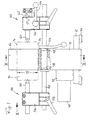
- the measuring device shown in FIGS. 1 to 4 has a housing 10, which is U-shaped in the end view according to FIG. 2 and four Legs 12 each with an elastic foot 14.
- the housing 10 has two hollow rectangular towers 16 which pass through a cuboidal space 18 from each other are separated. The whole case 10 and most of it Internals are in relation to a vertical central plane 20 designed symmetrically.
- the two towers 16 are each one vertical slot 22 to the space 18 open.
- a pair of columns 24 and, between this, a scale carrier 26 with one arranged thereon incremental scale 28 arranged vertically.
- the Columns 24 guide a vertically displaceable carriage 30, which corresponds to the housing 10 according to FIG. 3 U-shaped is.
- On the carriage 30 are on one side of the median plane 20, a transmitter 32 and a receiver 34 for laser beams arranged in alignment with the slots 22.
- the Carriage 30 also carries, in its central lower region, a scanning head 36, which together with the scale 28th forms a digital path measuring device.
- a motor 40 is attached to the housing 10, which is preferably an electric DC motor and via a reduction gear 42 and one inside of the housing 10 arranged crank mechanism 44 a roller 46 drives which engages in the horizontal groove 38, so that the carriage 30 vertically open with the motor 40 running makes descending movements.
- the housing 10 also has a pair of horizontal passages 48, which are longitudinal, parallel and symmetrical to Middle plane 20 extend and as supports for a bracket 50 serve.
- the bracket has 50 two parallel horizontal rods 52, which means a clamping device 54 on the housing 10 interchangeable are clamped and carry two supports 56, which adjustable along the rods 52 and by means of a toggle each 58 can be clamped.
- each a mandrel 60 the tip in the vertical central plane 20.
- One of the mandrels is 60 in its support 56 guided longitudinally, by a Spring 62 biased towards the housing 10 and by means of a Toggle 64 can be lifted off.
- the other mandrel 60 is on the associated Support 56 in a selectable position from the outset clamped.
- a measurement object 70 is shown a cylindrical shaft, centered between the mandrels 60 clamped; 5 and 6, the measurement object 70, again a cylindrical shaft, however, on two of the support prisms 68 launched. In both cases it is the target 70 symmetrical with respect to the central plane 20 of the measuring device arranged such that a target to be measured on the measurement object 70
- Dimension 72 in the example shown one in the middle plane 20, i.e. vertical, diameter to be measured, in the height range between the lower and upper ends of the Slots 22 is located.
- the dimension 72 is determined in that the contours visible in side view according to FIGS. 1, 4 and 5 74 of the measurement object 70 with one emitted by the transmitter 32 and energy beam passing through the slots 22 76 can be scanned.
- the energy beam 76 is preferred a laser beam in the red light area, which in the Middle plane 20 is focused.
- the transmitter 32 is switched on and engine 40 started for a period of time, during which the crank mechanism 44 at least one complete Revolution.
- the sled goes out of his drawn in Fig. 3 and 4 with full lines bottom dead center in the direction of arrow 78 upwards in its top dead center position indicated by dashed lines, and back to its bottom dead center position emotional.
- Measuring programs can also be selected in which the Carriage 30 performs several up and down movements and for which a correspondingly larger selection of measurement results won and finally interpolated.
Landscapes
- Physics & Mathematics (AREA)
- General Physics & Mathematics (AREA)
- Length Measuring Devices By Optical Means (AREA)
Description
- Fig. 1
- ein erfindungsgemäßes Meßgerät in Seitenansicht,
- Fig. 2
- die Stirnansicht in Richtung des Pfeils II in Fig. 1,
- Fig. 3
- den senkrechten Querschnitt III-III in Fig. 1,
- Fig. 4
- den senkrechten Längsschnitt IV-IV in Fig. 3,
- Fig. 5
- eine Ausführungsvariante des erfindungsgemäßen Meßgerätes in einer der Fig. 1 entsprechenden Seitenansicht und
- Fig. 6
- die Ausführungsvariante gemäß Fig. 5 in einer der Fig. 2 entsprechenden Stirnansicht.
Claims (5)
- Meßgerät zum Scannen von Maßen, insbes. Durchmessern, von Meßobjekten (70), mitdadurch gekennzeichnet, daßeiner Führung, die eine Mittelebene (20) des Meßgerätes definiert,einer Halterung (50), mit der sich ein Meßobjekt (70) in der Mittelebene (20) in einer Stellung halten läßt, in der sich ein interessierendes Maß (72) parallel zur Führung erstreckt, - einem Schlitten (30), der auf einer Seite der Mittelebene (20) einen Sender (32), und auf der anderen Seite einen Empfänger (34), für einen quer zur Mittelebene (20) und zum interessierenden Maß (72) verlaufenden Energiestrahl (76) trägt,einer Vorrichtung (40-46) zum Bewegen des Schlittens (30) längs der Führung,einer Wegmeßeinrichtung (26,28,36) zum Messen der Bewegungen des Schlittens (30) längs der Führung, undeiner Auswerteinrichtung, die aus Stellungen des Schlittens (30), in denen der zunächst vom Empfänger (34) empfangene Energiestrahl (76) vom Meßobjekt (70) unterbrochen, und dann wieder empfangen wird, das interessierende Maß (72) ermittelt,der Energiestrahl (76) auf die Mittelebene (20) fokussiert ist, unddie Wegmeßeinrichtung (26,28,36) einen in der Mittelebene (20) angeordneten Maßstabträger (26) aufweist.
- Meßgerät nach Anspruch 1,
dadurch gekennzeichnet, daß der Engergiestrahl (76) ein Laserstrahl ist. - Meßgerät nach Anspruch 1 oder 2,
dadurch gekennzeichnet, daß der Schlitten (30) an einem Paar Säulen (24) geführt ist, die auf je einer Seite der Mittelebene (20) angeordnet sind. - Meßgerät nach einem der Ansprüche 1 bis 3,
dadurch gekennzeichnet, daß die Halterung (50) ein Paar Stangen (52) aufweist, die sich auf je einer Seite der Mittelebene (20) parallel zu dieser erstrecken und einstellbare Abstützungen (56) für das Meßobjekt (70) tragen. - Meßgerät nach einem der Ansprüche 1 bis 4,
dadurch gekennzeichnet, daß der Schlitten (30) von einem Motor (40) über einen Kurbeltrieb (44) antreibbar ist.
Applications Claiming Priority (3)
| Application Number | Priority Date | Filing Date | Title |
|---|---|---|---|
| DE19738977A DE19738977A1 (de) | 1997-09-05 | 1997-09-05 | Meßgerät zum Scannen von Maßen, insbesondere Durchmessern |
| DE19738977 | 1997-09-05 | ||
| PCT/EP1998/005647 WO1999013292A1 (de) | 1997-09-05 | 1998-09-04 | Messgerät zum scannen von massen, insbes. durchmessern |
Publications (2)
| Publication Number | Publication Date |
|---|---|
| EP0937228A1 EP0937228A1 (de) | 1999-08-25 |
| EP0937228B1 true EP0937228B1 (de) | 2002-06-05 |
Family
ID=7841380
Family Applications (1)
| Application Number | Title | Priority Date | Filing Date |
|---|---|---|---|
| EP98947525A Expired - Lifetime EP0937228B1 (de) | 1997-09-05 | 1998-09-04 | Messgerät zum scannen von massen, insbes. durchmessern |
Country Status (5)
| Country | Link |
|---|---|
| US (1) | US6141106A (de) |
| EP (1) | EP0937228B1 (de) |
| JP (1) | JP2001508878A (de) |
| DE (2) | DE19738977A1 (de) |
| WO (1) | WO1999013292A1 (de) |
Families Citing this family (15)
| Publication number | Priority date | Publication date | Assignee | Title |
|---|---|---|---|---|
| US7227163B2 (en) * | 2002-06-17 | 2007-06-05 | Johnson Stanley P | Product inspection system and a method for implementing same |
| US8035094B2 (en) | 2002-06-17 | 2011-10-11 | Quest Metrology, LLC | Methods for measuring at least one physical characteristic of a component |
| US8410466B2 (en) * | 2002-06-17 | 2013-04-02 | Quest Metrology Group, Llc | Non-contact component inspection system |
| US7745805B2 (en) | 2002-06-17 | 2010-06-29 | Johnson Thread-View Systems | Product inspection system and a method for implementing same that incorporates a correction factor |
| US7578165B1 (en) * | 2004-12-17 | 2009-08-25 | Interface Associates, Inc. | Measurement apparatus and methods for balloon catheters |
| ITBO20050146A1 (it) * | 2005-03-14 | 2006-09-15 | Marposs Spa | Apparecchiatura e metodo per il controllo di pezzi meccanici |
| WO2007075585A2 (en) | 2005-12-16 | 2007-07-05 | Interface Associates, Inc. | Multi-layer balloons for medical applications and methods for manufacturing the same |
| US8465295B2 (en) | 2008-02-06 | 2013-06-18 | The Mitre Corporation | Fluid percussion system and method for modeling penetrating brain injury |
| EP2539669A1 (de) * | 2010-02-25 | 2013-01-02 | Tesa Sa | Optisches messsystem |
| CN102901453B (zh) * | 2012-09-12 | 2015-06-10 | 深圳深蓝精机有限公司 | 圆轴长度、外径、跳动值及真圆度的测量装置及其测量方法 |
| US20160114141A1 (en) | 2014-10-27 | 2016-04-28 | Interface Associates, Inc. | Methods of manufacturing nested balloons utilizing pressurized constrained annealing |
| DE102016006659B4 (de) * | 2016-06-01 | 2020-12-17 | Hochschule Magdeburg-Stendal | Messsystem und Verfahren zur berührungslosen Vermessung von Werkstücken |
| CN110345830B (zh) * | 2019-06-04 | 2021-06-29 | 中交一公局第二工程有限公司 | 一种圆形钢筋检测装置 |
| CH720274A1 (de) * | 2022-11-25 | 2024-05-31 | Braecker Ag | Messvorrichtung zur Messung eines Durchmessers von Spinnzylindern, Verfahren und Schleifmaschine |
| CN116989685A (zh) * | 2023-03-23 | 2023-11-03 | 绍兴四玖科技有限公司 | 一种多功能测径仪 |
Family Cites Families (11)
| Publication number | Priority date | Publication date | Assignee | Title |
|---|---|---|---|---|
| SE325143B (de) * | 1966-07-19 | 1970-06-22 | Ingenioersfa Stig Morenius Ab | |
| US3749500A (en) * | 1970-12-23 | 1973-07-31 | Gen Electric | Optical caliper and edge detector-follower for automatic gaging |
| SE380342B (sv) * | 1973-02-14 | 1975-11-03 | Lasergruppen Konsult Ab | Forfarande och anordning for metning av ett metobjekts diameter, orundhet och lege |
| US4678337A (en) * | 1985-05-03 | 1987-07-07 | Laser Metric Systems, Inc. | Laser based gaging system and method of using same |
| GB2180337A (en) * | 1985-09-13 | 1987-03-25 | Tesa Metrology Ltd | Optical measurement apparatus |
| DE3630702A1 (de) * | 1986-09-09 | 1988-03-17 | Ulrich Wagensommer | Vorrichtung zum vermessen eines werkstueckes |
| US5005978A (en) * | 1989-11-06 | 1991-04-09 | Cyberoptics Corporation | Apparatus and method for the noncontact measurement of drill diameter, runout, and tip position |
| JPH04105006A (ja) * | 1990-08-24 | 1992-04-07 | Tokyo Seimitsu Co Ltd | 非接触測定装置 |
| DE4224253C1 (de) * | 1992-07-22 | 1994-03-03 | Kaspar Walter Maschf Kg | Verfahren und Einrichtung zum automatischen Bestimmen der Abmessungen von Druckzylindern |
| DE4238504C2 (de) * | 1992-11-14 | 1996-04-25 | Chiron Werke Gmbh | Verfahren zum Vermessen eines Werkzeuges |
| IT1281546B1 (it) * | 1995-04-13 | 1998-02-18 | Marposs Spa | Apparecchio di misura optoelettronico per il controllo di dimensioni lineari |
-
1997
- 1997-09-05 DE DE19738977A patent/DE19738977A1/de not_active Withdrawn
-
1998
- 1998-09-04 JP JP51507099A patent/JP2001508878A/ja active Pending
- 1998-09-04 EP EP98947525A patent/EP0937228B1/de not_active Expired - Lifetime
- 1998-09-04 DE DE59804307T patent/DE59804307D1/de not_active Expired - Fee Related
- 1998-09-04 WO PCT/EP1998/005647 patent/WO1999013292A1/de not_active Ceased
- 1998-09-04 US US09/269,838 patent/US6141106A/en not_active Expired - Fee Related
Also Published As
| Publication number | Publication date |
|---|---|
| DE59804307D1 (de) | 2002-07-11 |
| EP0937228A1 (de) | 1999-08-25 |
| WO1999013292A1 (de) | 1999-03-18 |
| US6141106A (en) | 2000-10-31 |
| DE19738977A1 (de) | 1999-03-18 |
| JP2001508878A (ja) | 2001-07-03 |
Similar Documents
| Publication | Publication Date | Title |
|---|---|---|
| WO1999013292A1 (de) | Messgerät zum scannen von massen, insbes. durchmessern | |
| DE4109866A1 (de) | Reparaturstand mit richtrahmen | |
| DE2507412A1 (de) | Vorrichtung zum ausrichten von fahrzeugen | |
| DE4022951C2 (de) | Biegerichtmaschine für Profilabschnitte | |
| AT413956B (de) | Schweissmaschine zum herstellen von drahtgittermatten | |
| DE3741590C2 (de) | ||
| EP0589240B1 (de) | Liegende Metallstrangpresse | |
| EP0222728A1 (de) | Vorrichtung zum Herstellen prismatischer oder pyramidenstumpfförmiger Balken | |
| DE3741591C2 (de) | ||
| DE19541899B4 (de) | Vorrichtung zum Spannen und Laserstrahlschweißen von Dünnblechen | |
| DE2538201B2 (de) | Mundstückwechselvorrichtung für eine Strangpresse | |
| DE2063041C3 (de) | Einrichtung zum Biegen von Stäben u.dgl | |
| DE2914026A1 (de) | Sortiermaschine fuer werkstuecke | |
| DE102020007294A1 (de) | System zum Positionieren einer Tischeinrichtung in einer Fertigungszelle | |
| DE2614127C3 (de) | Vorrichtung zur Parallelführung eines Arbeitsgerätes | |
| DE1136555B (de) | Vorrichtung zur Parallelfuehrung eines beweglichen Apparateteils eines Messgeraets, vorzugsweise eines Komparators, gegenueber einem feststehenden Apparateteil | |
| DE3807076C2 (de) | ||
| DE3529775A1 (de) | Vorrichtung zur herstellung von formteilen | |
| DE2620528C3 (de) | Vorrichtung zum Spannen von Walzgut im Arbeitsbereich eines Trennwerkzeuges, insbesondere eines Kreissägeblattes | |
| DE9014057U1 (de) | Transportvorrichtung für längliche Werkstücke | |
| DE2922535B1 (de) | Verfahren und Vorrichtung zur Bestimmung der Festigkeit von Kunststofflaschenkaesten | |
| DE3818447C1 (en) | Semiautomatic device for stripping the ends of conductors using insulation incision knives | |
| DE202004004382U1 (de) | Schweißhilfsvorrichtung | |
| DE102014002236A1 (de) | Objektträger für eine Vorrichtung zum Erfassen von dreidimensionalen Objekten, Vorrichtung mit eineam solchen Objektträger und Verfahren zum Erfassen von zumindest einem dreidimensionalen Objekt | |
| DE69207124T2 (de) | Scheibenschweissmaschine |
Legal Events
| Date | Code | Title | Description |
|---|---|---|---|
| PUAI | Public reference made under article 153(3) epc to a published international application that has entered the european phase |
Free format text: ORIGINAL CODE: 0009012 |
|
| 17P | Request for examination filed |
Effective date: 19990408 |
|
| AK | Designated contracting states |
Kind code of ref document: A1 Designated state(s): DE FR GB IT |
|
| GRAG | Despatch of communication of intention to grant |
Free format text: ORIGINAL CODE: EPIDOS AGRA |
|
| 17Q | First examination report despatched |
Effective date: 20010926 |
|
| GRAG | Despatch of communication of intention to grant |
Free format text: ORIGINAL CODE: EPIDOS AGRA |
|
| GRAG | Despatch of communication of intention to grant |
Free format text: ORIGINAL CODE: EPIDOS AGRA |
|
| GRAH | Despatch of communication of intention to grant a patent |
Free format text: ORIGINAL CODE: EPIDOS IGRA |
|
| GRAH | Despatch of communication of intention to grant a patent |
Free format text: ORIGINAL CODE: EPIDOS IGRA |
|
| GRAA | (expected) grant |
Free format text: ORIGINAL CODE: 0009210 |
|
| AK | Designated contracting states |
Kind code of ref document: B1 Designated state(s): DE FR GB IT |
|
| REG | Reference to a national code |
Ref country code: GB Ref legal event code: FG4D Free format text: NOT ENGLISH |
|
| REF | Corresponds to: |
Ref document number: 59804307 Country of ref document: DE Date of ref document: 20020711 |
|
| ET | Fr: translation filed | ||
| PLBE | No opposition filed within time limit |
Free format text: ORIGINAL CODE: 0009261 |
|
| STAA | Information on the status of an ep patent application or granted ep patent |
Free format text: STATUS: NO OPPOSITION FILED WITHIN TIME LIMIT |
|
| 26N | No opposition filed |
Effective date: 20030306 |
|
| PGFP | Annual fee paid to national office [announced via postgrant information from national office to epo] |
Ref country code: GB Payment date: 20030722 Year of fee payment: 6 |
|
| PGFP | Annual fee paid to national office [announced via postgrant information from national office to epo] |
Ref country code: FR Payment date: 20030723 Year of fee payment: 6 |
|
| PG25 | Lapsed in a contracting state [announced via postgrant information from national office to epo] |
Ref country code: GB Free format text: LAPSE BECAUSE OF NON-PAYMENT OF DUE FEES Effective date: 20040904 |
|
| GBPC | Gb: european patent ceased through non-payment of renewal fee |
Effective date: 20040904 |
|
| PG25 | Lapsed in a contracting state [announced via postgrant information from national office to epo] |
Ref country code: FR Free format text: LAPSE BECAUSE OF NON-PAYMENT OF DUE FEES Effective date: 20050531 |
|
| REG | Reference to a national code |
Ref country code: FR Ref legal event code: ST |
|
| PG25 | Lapsed in a contracting state [announced via postgrant information from national office to epo] |
Ref country code: IT Free format text: LAPSE BECAUSE OF NON-PAYMENT OF DUE FEES Effective date: 20050904 |
|
| PGFP | Annual fee paid to national office [announced via postgrant information from national office to epo] |
Ref country code: DE Payment date: 20050926 Year of fee payment: 8 |
|
| PG25 | Lapsed in a contracting state [announced via postgrant information from national office to epo] |
Ref country code: DE Free format text: LAPSE BECAUSE OF NON-PAYMENT OF DUE FEES Effective date: 20070403 |