EP0937180B1 - Three-dimensional, amorphous-patterned, nesting-resistant sheet materials and method and apparatus for making same - Google Patents
Three-dimensional, amorphous-patterned, nesting-resistant sheet materials and method and apparatus for making same Download PDFInfo
- Publication number
- EP0937180B1 EP0937180B1 EP97901373A EP97901373A EP0937180B1 EP 0937180 B1 EP0937180 B1 EP 0937180B1 EP 97901373 A EP97901373 A EP 97901373A EP 97901373 A EP97901373 A EP 97901373A EP 0937180 B1 EP0937180 B1 EP 0937180B1
- Authority
- EP
- European Patent Office
- Prior art keywords
- dimensional
- protrusions
- pattern
- sheet material
- shapes
- Prior art date
- Legal status (The legal status is an assumption and is not a legal conclusion. Google has not performed a legal analysis and makes no representation as to the accuracy of the status listed.)
- Expired - Lifetime
Links
- 239000000463 material Substances 0.000 title claims description 216
- 238000000034 method Methods 0.000 title claims description 57
- 239000000126 substance Substances 0.000 claims description 74
- 239000000853 adhesive Substances 0.000 claims description 30
- 230000001070 adhesive effect Effects 0.000 claims description 30
- 238000004519 manufacturing process Methods 0.000 claims description 14
- 238000000576 coating method Methods 0.000 claims description 9
- 239000011248 coating agent Substances 0.000 claims description 8
- 239000010935 stainless steel Substances 0.000 claims description 7
- 229910001220 stainless steel Inorganic materials 0.000 claims description 7
- 238000003856 thermoforming Methods 0.000 claims description 4
- 238000004049 embossing Methods 0.000 claims description 2
- 230000001131 transforming effect Effects 0.000 claims 1
- 230000006911 nucleation Effects 0.000 description 27
- 238000010899 nucleation Methods 0.000 description 27
- 239000010410 layer Substances 0.000 description 20
- 230000008569 process Effects 0.000 description 11
- 238000004590 computer program Methods 0.000 description 8
- 238000013461 design Methods 0.000 description 7
- 230000008901 benefit Effects 0.000 description 6
- 230000015572 biosynthetic process Effects 0.000 description 6
- 230000000694 effects Effects 0.000 description 6
- 238000005755 formation reaction Methods 0.000 description 6
- 229920001903 high density polyethylene Polymers 0.000 description 6
- 239000004700 high-density polyethylene Substances 0.000 description 6
- 239000012528 membrane Substances 0.000 description 6
- 238000003860 storage Methods 0.000 description 6
- 239000004831 Hot glue Substances 0.000 description 5
- 230000004913 activation Effects 0.000 description 5
- 238000004140 cleaning Methods 0.000 description 5
- 230000007423 decrease Effects 0.000 description 5
- 238000009826 distribution Methods 0.000 description 5
- 239000007788 liquid Substances 0.000 description 5
- 229910052751 metal Inorganic materials 0.000 description 5
- 239000002184 metal Substances 0.000 description 5
- 230000000704 physical effect Effects 0.000 description 5
- 239000007858 starting material Substances 0.000 description 5
- 238000012360 testing method Methods 0.000 description 5
- 239000004820 Pressure-sensitive adhesive Substances 0.000 description 4
- 239000013543 active substance Substances 0.000 description 4
- 238000013459 approach Methods 0.000 description 4
- 239000000919 ceramic Substances 0.000 description 4
- 230000007717 exclusion Effects 0.000 description 4
- 230000036961 partial effect Effects 0.000 description 4
- 229920000642 polymer Polymers 0.000 description 4
- 230000002028 premature Effects 0.000 description 4
- 239000007787 solid Substances 0.000 description 4
- 238000004804 winding Methods 0.000 description 4
- 238000004364 calculation method Methods 0.000 description 3
- 230000006835 compression Effects 0.000 description 3
- 238000007906 compression Methods 0.000 description 3
- 230000003247 decreasing effect Effects 0.000 description 3
- 239000004816 latex Substances 0.000 description 3
- 229920000126 latex Polymers 0.000 description 3
- 239000000203 mixture Substances 0.000 description 3
- 238000001259 photo etching Methods 0.000 description 3
- 230000002829 reductive effect Effects 0.000 description 3
- 229920005989 resin Polymers 0.000 description 3
- 239000011347 resin Substances 0.000 description 3
- 238000005096 rolling process Methods 0.000 description 3
- 229910052727 yttrium Inorganic materials 0.000 description 3
- PXHVJJICTQNCMI-UHFFFAOYSA-N Nickel Chemical compound [Ni] PXHVJJICTQNCMI-UHFFFAOYSA-N 0.000 description 2
- 238000003491 array Methods 0.000 description 2
- 230000009286 beneficial effect Effects 0.000 description 2
- 230000001413 cellular effect Effects 0.000 description 2
- 239000000470 constituent Substances 0.000 description 2
- 230000001747 exhibiting effect Effects 0.000 description 2
- 238000001125 extrusion Methods 0.000 description 2
- 230000000670 limiting effect Effects 0.000 description 2
- 229920001684 low density polyethylene Polymers 0.000 description 2
- 239000004702 low-density polyethylene Substances 0.000 description 2
- 238000012986 modification Methods 0.000 description 2
- 230000004048 modification Effects 0.000 description 2
- 239000000123 paper Substances 0.000 description 2
- -1 polyethylene Polymers 0.000 description 2
- 229920001296 polysiloxane Polymers 0.000 description 2
- 230000010076 replication Effects 0.000 description 2
- 238000003466 welding Methods 0.000 description 2
- 229910001369 Brass Inorganic materials 0.000 description 1
- 229920003043 Cellulose fiber Polymers 0.000 description 1
- RYGMFSIKBFXOCR-UHFFFAOYSA-N Copper Chemical compound [Cu] RYGMFSIKBFXOCR-UHFFFAOYSA-N 0.000 description 1
- 239000004593 Epoxy Substances 0.000 description 1
- VGGSQFUCUMXWEO-UHFFFAOYSA-N Ethene Chemical compound C=C VGGSQFUCUMXWEO-UHFFFAOYSA-N 0.000 description 1
- FYYHWMGAXLPEAU-UHFFFAOYSA-N Magnesium Chemical compound [Mg] FYYHWMGAXLPEAU-UHFFFAOYSA-N 0.000 description 1
- 239000004677 Nylon Substances 0.000 description 1
- 239000004698 Polyethylene Substances 0.000 description 1
- 239000004743 Polypropylene Substances 0.000 description 1
- 229920001328 Polyvinylidene chloride Polymers 0.000 description 1
- 229920003295 Radel® Polymers 0.000 description 1
- 230000009471 action Effects 0.000 description 1
- 239000012790 adhesive layer Substances 0.000 description 1
- 229910045601 alloy Inorganic materials 0.000 description 1
- 239000000956 alloy Substances 0.000 description 1
- 229910052782 aluminium Inorganic materials 0.000 description 1
- XAGFODPZIPBFFR-UHFFFAOYSA-N aluminium Chemical compound [Al] XAGFODPZIPBFFR-UHFFFAOYSA-N 0.000 description 1
- 239000010407 anodic oxide Substances 0.000 description 1
- 238000005452 bending Methods 0.000 description 1
- 239000010951 brass Substances 0.000 description 1
- 239000004568 cement Substances 0.000 description 1
- 230000008859 change Effects 0.000 description 1
- 238000006243 chemical reaction Methods 0.000 description 1
- 239000003795 chemical substances by application Substances 0.000 description 1
- 238000004040 coloring Methods 0.000 description 1
- 239000002131 composite material Substances 0.000 description 1
- 239000004567 concrete Substances 0.000 description 1
- 235000013409 condiments Nutrition 0.000 description 1
- 238000010276 construction Methods 0.000 description 1
- 238000011109 contamination Methods 0.000 description 1
- 238000001816 cooling Methods 0.000 description 1
- 229910052802 copper Inorganic materials 0.000 description 1
- 239000010949 copper Substances 0.000 description 1
- 239000011243 crosslinked material Substances 0.000 description 1
- 239000013013 elastic material Substances 0.000 description 1
- 229920001971 elastomer Polymers 0.000 description 1
- 238000010894 electron beam technology Methods 0.000 description 1
- 238000005516 engineering process Methods 0.000 description 1
- 238000005530 etching Methods 0.000 description 1
- 239000004744 fabric Substances 0.000 description 1
- 230000001815 facial effect Effects 0.000 description 1
- 230000009969 flowable effect Effects 0.000 description 1
- 239000012530 fluid Substances 0.000 description 1
- 239000006260 foam Substances 0.000 description 1
- 239000011888 foil Substances 0.000 description 1
- 239000000499 gel Substances 0.000 description 1
- 239000011521 glass Substances 0.000 description 1
- 230000005484 gravity Effects 0.000 description 1
- 238000010438 heat treatment Methods 0.000 description 1
- 229920006262 high density polyethylene film Polymers 0.000 description 1
- 230000002209 hydrophobic effect Effects 0.000 description 1
- 230000002401 inhibitory effect Effects 0.000 description 1
- 239000002648 laminated material Substances 0.000 description 1
- 239000006210 lotion Substances 0.000 description 1
- 229910052749 magnesium Inorganic materials 0.000 description 1
- 239000011777 magnesium Substances 0.000 description 1
- 238000005259 measurement Methods 0.000 description 1
- 238000010297 mechanical methods and process Methods 0.000 description 1
- 230000005226 mechanical processes and functions Effects 0.000 description 1
- QSHDDOUJBYECFT-UHFFFAOYSA-N mercury Chemical compound [Hg] QSHDDOUJBYECFT-UHFFFAOYSA-N 0.000 description 1
- 229910052753 mercury Inorganic materials 0.000 description 1
- 150000002739 metals Chemical class 0.000 description 1
- 229910052759 nickel Inorganic materials 0.000 description 1
- 239000004745 nonwoven fabric Substances 0.000 description 1
- 229920001778 nylon Polymers 0.000 description 1
- 230000008520 organization Effects 0.000 description 1
- 238000004806 packaging method and process Methods 0.000 description 1
- 239000002245 particle Substances 0.000 description 1
- 239000006072 paste Substances 0.000 description 1
- 239000002304 perfume Substances 0.000 description 1
- 230000002093 peripheral effect Effects 0.000 description 1
- 229920000573 polyethylene Polymers 0.000 description 1
- 229920000139 polyethylene terephthalate Polymers 0.000 description 1
- 239000005020 polyethylene terephthalate Substances 0.000 description 1
- 229920006254 polymer film Polymers 0.000 description 1
- 229920000098 polyolefin Polymers 0.000 description 1
- 229920001155 polypropylene Polymers 0.000 description 1
- 229920001343 polytetrafluoroethylene Polymers 0.000 description 1
- 239000004810 polytetrafluoroethylene Substances 0.000 description 1
- 229920000915 polyvinyl chloride Polymers 0.000 description 1
- 239000004800 polyvinyl chloride Substances 0.000 description 1
- 239000005033 polyvinylidene chloride Substances 0.000 description 1
- 239000000843 powder Substances 0.000 description 1
- 239000002243 precursor Substances 0.000 description 1
- 230000003252 repetitive effect Effects 0.000 description 1
- 230000004044 response Effects 0.000 description 1
- 230000002441 reversible effect Effects 0.000 description 1
- 239000005060 rubber Substances 0.000 description 1
- 239000003566 sealing material Substances 0.000 description 1
- 238000000926 separation method Methods 0.000 description 1
- 239000002356 single layer Substances 0.000 description 1
- 238000007711 solidification Methods 0.000 description 1
- 230000008023 solidification Effects 0.000 description 1
- 238000001179 sorption measurement Methods 0.000 description 1
- 238000013179 statistical model Methods 0.000 description 1
- 239000004575 stone Substances 0.000 description 1
- 239000000758 substrate Substances 0.000 description 1
- 239000000725 suspension Substances 0.000 description 1
- 229920001187 thermosetting polymer Polymers 0.000 description 1
- 238000012546 transfer Methods 0.000 description 1
- 239000001993 wax Substances 0.000 description 1
- 239000002023 wood Substances 0.000 description 1
Images


Classifications
-
- B—PERFORMING OPERATIONS; TRANSPORTING
- B29—WORKING OF PLASTICS; WORKING OF SUBSTANCES IN A PLASTIC STATE IN GENERAL
- B29C—SHAPING OR JOINING OF PLASTICS; SHAPING OF MATERIAL IN A PLASTIC STATE, NOT OTHERWISE PROVIDED FOR; AFTER-TREATMENT OF THE SHAPED PRODUCTS, e.g. REPAIRING
- B29C51/00—Shaping by thermoforming, i.e. shaping sheets or sheet like preforms after heating, e.g. shaping sheets in matched moulds or by deep-drawing; Apparatus therefor
- B29C51/18—Thermoforming apparatus
- B29C51/20—Thermoforming apparatus having movable moulds or mould parts
- B29C51/22—Thermoforming apparatus having movable moulds or mould parts rotatable about an axis
- B29C51/225—Thermoforming apparatus having movable moulds or mould parts rotatable about an axis mounted on a vacuum drum
-
- B—PERFORMING OPERATIONS; TRANSPORTING
- B32—LAYERED PRODUCTS
- B32B—LAYERED PRODUCTS, i.e. PRODUCTS BUILT-UP OF STRATA OF FLAT OR NON-FLAT, e.g. CELLULAR OR HONEYCOMB, FORM
- B32B7/00—Layered products characterised by the relation between layers; Layered products characterised by the relative orientation of features between layers, or by the relative values of a measurable parameter between layers, i.e. products comprising layers having different physical, chemical or physicochemical properties; Layered products characterised by the interconnection of layers
-
- B—PERFORMING OPERATIONS; TRANSPORTING
- B31—MAKING ARTICLES OF PAPER, CARDBOARD OR MATERIAL WORKED IN A MANNER ANALOGOUS TO PAPER; WORKING PAPER, CARDBOARD OR MATERIAL WORKED IN A MANNER ANALOGOUS TO PAPER
- B31F—MECHANICAL WORKING OR DEFORMATION OF PAPER, CARDBOARD OR MATERIAL WORKED IN A MANNER ANALOGOUS TO PAPER
- B31F1/00—Mechanical deformation without removing material, e.g. in combination with laminating
- B31F1/07—Embossing, i.e. producing impressions formed by locally deep-drawing, e.g. using rolls provided with complementary profiles
-
- B—PERFORMING OPERATIONS; TRANSPORTING
- B65—CONVEYING; PACKING; STORING; HANDLING THIN OR FILAMENTARY MATERIAL
- B65D—CONTAINERS FOR STORAGE OR TRANSPORT OF ARTICLES OR MATERIALS, e.g. BAGS, BARRELS, BOTTLES, BOXES, CANS, CARTONS, CRATES, DRUMS, JARS, TANKS, HOPPERS, FORWARDING CONTAINERS; ACCESSORIES, CLOSURES, OR FITTINGS THEREFOR; PACKAGING ELEMENTS; PACKAGES
- B65D65/00—Wrappers or flexible covers; Packaging materials of special type or form
- B65D65/38—Packaging materials of special type or form
-
- D—TEXTILES; PAPER
- D21—PAPER-MAKING; PRODUCTION OF CELLULOSE
- D21H—PULP COMPOSITIONS; PREPARATION THEREOF NOT COVERED BY SUBCLASSES D21C OR D21D; IMPREGNATING OR COATING OF PAPER; TREATMENT OF FINISHED PAPER NOT COVERED BY CLASS B31 OR SUBCLASS D21G; PAPER NOT OTHERWISE PROVIDED FOR
- D21H27/00—Special paper not otherwise provided for, e.g. made by multi-step processes
- D21H27/30—Multi-ply
- D21H27/40—Multi-ply at least one of the sheets being non-planar, e.g. crêped
-
- B—PERFORMING OPERATIONS; TRANSPORTING
- B31—MAKING ARTICLES OF PAPER, CARDBOARD OR MATERIAL WORKED IN A MANNER ANALOGOUS TO PAPER; WORKING PAPER, CARDBOARD OR MATERIAL WORKED IN A MANNER ANALOGOUS TO PAPER
- B31F—MECHANICAL WORKING OR DEFORMATION OF PAPER, CARDBOARD OR MATERIAL WORKED IN A MANNER ANALOGOUS TO PAPER
- B31F2201/00—Mechanical deformation of paper or cardboard without removing material
- B31F2201/07—Embossing
- B31F2201/0707—Embossing by tools working continuously
- B31F2201/0715—The tools being rollers
- B31F2201/0723—Characteristics of the rollers
- B31F2201/0733—Pattern
-
- B—PERFORMING OPERATIONS; TRANSPORTING
- B31—MAKING ARTICLES OF PAPER, CARDBOARD OR MATERIAL WORKED IN A MANNER ANALOGOUS TO PAPER; WORKING PAPER, CARDBOARD OR MATERIAL WORKED IN A MANNER ANALOGOUS TO PAPER
- B31F—MECHANICAL WORKING OR DEFORMATION OF PAPER, CARDBOARD OR MATERIAL WORKED IN A MANNER ANALOGOUS TO PAPER
- B31F2201/00—Mechanical deformation of paper or cardboard without removing material
- B31F2201/07—Embossing
- B31F2201/0707—Embossing by tools working continuously
- B31F2201/0754—The tools being other than rollers, e.g. belts or plates
-
- B—PERFORMING OPERATIONS; TRANSPORTING
- B31—MAKING ARTICLES OF PAPER, CARDBOARD OR MATERIAL WORKED IN A MANNER ANALOGOUS TO PAPER; WORKING PAPER, CARDBOARD OR MATERIAL WORKED IN A MANNER ANALOGOUS TO PAPER
- B31F—MECHANICAL WORKING OR DEFORMATION OF PAPER, CARDBOARD OR MATERIAL WORKED IN A MANNER ANALOGOUS TO PAPER
- B31F2201/00—Mechanical deformation of paper or cardboard without removing material
- B31F2201/07—Embossing
- B31F2201/0758—Characteristics of the embossed product
- B31F2201/0761—Multi-layered
-
- B—PERFORMING OPERATIONS; TRANSPORTING
- B31—MAKING ARTICLES OF PAPER, CARDBOARD OR MATERIAL WORKED IN A MANNER ANALOGOUS TO PAPER; WORKING PAPER, CARDBOARD OR MATERIAL WORKED IN A MANNER ANALOGOUS TO PAPER
- B31F—MECHANICAL WORKING OR DEFORMATION OF PAPER, CARDBOARD OR MATERIAL WORKED IN A MANNER ANALOGOUS TO PAPER
- B31F2201/00—Mechanical deformation of paper or cardboard without removing material
- B31F2201/07—Embossing
- B31F2201/0784—Auxiliary operations
- B31F2201/0787—Applying adhesive
-
- D—TEXTILES; PAPER
- D21—PAPER-MAKING; PRODUCTION OF CELLULOSE
- D21H—PULP COMPOSITIONS; PREPARATION THEREOF NOT COVERED BY SUBCLASSES D21C OR D21D; IMPREGNATING OR COATING OF PAPER; TREATMENT OF FINISHED PAPER NOT COVERED BY CLASS B31 OR SUBCLASS D21G; PAPER NOT OTHERWISE PROVIDED FOR
- D21H27/00—Special paper not otherwise provided for, e.g. made by multi-step processes
- D21H27/02—Patterned paper
-
- D—TEXTILES; PAPER
- D21—PAPER-MAKING; PRODUCTION OF CELLULOSE
- D21H—PULP COMPOSITIONS; PREPARATION THEREOF NOT COVERED BY SUBCLASSES D21C OR D21D; IMPREGNATING OR COATING OF PAPER; TREATMENT OF FINISHED PAPER NOT COVERED BY CLASS B31 OR SUBCLASS D21G; PAPER NOT OTHERWISE PROVIDED FOR
- D21H27/00—Special paper not otherwise provided for, e.g. made by multi-step processes
- D21H27/10—Packing paper
-
- Y—GENERAL TAGGING OF NEW TECHNOLOGICAL DEVELOPMENTS; GENERAL TAGGING OF CROSS-SECTIONAL TECHNOLOGIES SPANNING OVER SEVERAL SECTIONS OF THE IPC; TECHNICAL SUBJECTS COVERED BY FORMER USPC CROSS-REFERENCE ART COLLECTIONS [XRACs] AND DIGESTS
- Y10—TECHNICAL SUBJECTS COVERED BY FORMER USPC
- Y10T—TECHNICAL SUBJECTS COVERED BY FORMER US CLASSIFICATION
- Y10T156/00—Adhesive bonding and miscellaneous chemical manufacture
- Y10T156/10—Methods of surface bonding and/or assembly therefor
- Y10T156/1002—Methods of surface bonding and/or assembly therefor with permanent bending or reshaping or surface deformation of self sustaining lamina
- Y10T156/1007—Running or continuous length work
- Y10T156/1023—Surface deformation only [e.g., embossing]
-
- Y—GENERAL TAGGING OF NEW TECHNOLOGICAL DEVELOPMENTS; GENERAL TAGGING OF CROSS-SECTIONAL TECHNOLOGIES SPANNING OVER SEVERAL SECTIONS OF THE IPC; TECHNICAL SUBJECTS COVERED BY FORMER USPC CROSS-REFERENCE ART COLLECTIONS [XRACs] AND DIGESTS
- Y10—TECHNICAL SUBJECTS COVERED BY FORMER USPC
- Y10T—TECHNICAL SUBJECTS COVERED BY FORMER US CLASSIFICATION
- Y10T428/00—Stock material or miscellaneous articles
- Y10T428/24—Structurally defined web or sheet [e.g., overall dimension, etc.]
- Y10T428/24355—Continuous and nonuniform or irregular surface on layer or component [e.g., roofing, etc.]
-
- Y—GENERAL TAGGING OF NEW TECHNOLOGICAL DEVELOPMENTS; GENERAL TAGGING OF CROSS-SECTIONAL TECHNOLOGIES SPANNING OVER SEVERAL SECTIONS OF THE IPC; TECHNICAL SUBJECTS COVERED BY FORMER USPC CROSS-REFERENCE ART COLLECTIONS [XRACs] AND DIGESTS
- Y10—TECHNICAL SUBJECTS COVERED BY FORMER USPC
- Y10T—TECHNICAL SUBJECTS COVERED BY FORMER US CLASSIFICATION
- Y10T428/00—Stock material or miscellaneous articles
- Y10T428/24—Structurally defined web or sheet [e.g., overall dimension, etc.]
- Y10T428/24479—Structurally defined web or sheet [e.g., overall dimension, etc.] including variation in thickness
- Y10T428/24612—Composite web or sheet
-
- Y—GENERAL TAGGING OF NEW TECHNOLOGICAL DEVELOPMENTS; GENERAL TAGGING OF CROSS-SECTIONAL TECHNOLOGIES SPANNING OVER SEVERAL SECTIONS OF THE IPC; TECHNICAL SUBJECTS COVERED BY FORMER USPC CROSS-REFERENCE ART COLLECTIONS [XRACs] AND DIGESTS
- Y10—TECHNICAL SUBJECTS COVERED BY FORMER USPC
- Y10T—TECHNICAL SUBJECTS COVERED BY FORMER US CLASSIFICATION
- Y10T428/00—Stock material or miscellaneous articles
- Y10T428/28—Web or sheet containing structurally defined element or component and having an adhesive outermost layer
-
- Y—GENERAL TAGGING OF NEW TECHNOLOGICAL DEVELOPMENTS; GENERAL TAGGING OF CROSS-SECTIONAL TECHNOLOGIES SPANNING OVER SEVERAL SECTIONS OF THE IPC; TECHNICAL SUBJECTS COVERED BY FORMER USPC CROSS-REFERENCE ART COLLECTIONS [XRACs] AND DIGESTS
- Y10—TECHNICAL SUBJECTS COVERED BY FORMER USPC
- Y10T—TECHNICAL SUBJECTS COVERED BY FORMER US CLASSIFICATION
- Y10T428/00—Stock material or miscellaneous articles
- Y10T428/31—Surface property or characteristic of web, sheet or block
Definitions
- the present invention relates to three-dimensional sheet materials which resist nesting of superimposed layers into one another. More particularly, the present invention relates to three-dimensional sheet materials having a plurality of three-dimensional protrusions extending outwardly from at least one side of the material which form an amorphous pattern. The present invention further relates to a method and apparatus for forming such three-dimensional sheet materials.
- Sheet materials having three-dimensional surfaces are well known in the art and have been utilized in many different applications. Such materials may be made in planar sheet form and remain in that form throughout handling or they may be made in continuous web form and be wound on rolls for handling. When in planar form, nesting of sheets may be useful to reduce stack height, for example. However, when wound onto rolls, nesting frequently causes significant problems. For example, nesting of layers having three dimensional surfaces on a roll may create difficulty unwinding the roll due to frictional engagement. Also, if nesting occurs more deeply at one end of the roll than the other end, roll telescoping may occur.
- Nesting of any three-dimensional material can occur if protrusions in overlying webs or portions of the same web interlock with one another due to their size, shape, location, and/or geometrical arrangement.
- Two types of nesting or interlocking can occur: face-to-face nesting and face-to-back nesting.
- Face-to-face nesting can occur when two analogous faces of the same web or faces of plural webs are brought into contact and protrusions of each web or web portion enter valleys or spaces between adjacent protrusions of the other web or web portion.
- Face-to-back nesting can occur when opposing sides of the same web or dissimilar sides of plural webs are brought into contact and protrusions of one web or web portion enter the hollow "negative" side of protrusions of the other web or web portion.
- Such face-to-back nesting is of particular concern with three-dimensional sheet materials having hollow three-dimensional protrusions such as those of the present invention. If a web only exhibits three-dimensional surface features on one surface, i.e., the back surface is generally planar, then face-to-face nesting emerges as the primary consideration as face-to-back nesting cannot occur.
- Nesting of adjacent layers or windings of a continuous web when rolled can create difficulty in unrolling the end of the web due to the frictional engagement which occurs with face-to-back nesting.
- Nesting of stacked individual layers or plies of three-dimensional web materials can result in removal of multiple sheets from a container when only a single sheet is desired, etc. While the ability of the web to nest with itself or with other webs may create a certain degree of difficulty in and of itself, where the three-dimensional web structure is utilized as a carrier for an active substance such as, for example, an adhesive, nesting can cause additional difficulties including premature adhesion and/or contamination of the active substance.
- One such three-dimensional sheet material, as well as methods and apparatus for manufacturing same, is described in greater detail in commonly-assigned, co-pending U.S. Patent Application Serial No. 08/584,638, entitled “Composite Material Releasably Sealable to a Target Surface When Pressed Thereagainst and Method of Making", filed January 10, 1996 in the names of Peter W. Hamilton and Kenneth S. McGuire, the disclosure of which is hereby incorporated herein by reference.
- the present invention provides a three-dimensional, nesting-resistant sheet material having a first side and a second side.
- the first side comprises at least one region having a plurality of spaced three-dimensional protrusions extending outwardly from the first side in a pattern as defined in the present claim 1.
- the second side comprises a plurality of spaced, three-dimensional hollow depressions corresponding to the protrusions, such that the protrusions are hollow.
- the protrusions are separated by an interconnected network of three-dimensional spaces between adjacent protrusions.
- the spaces preferably have substantially equivalent widths throughout the pattern and may be partially filled with an adhesive.
- the forming structure may be made according to the present invention by a method comprising the steps amorphous two-dimensional pattern of interlocking two-dimensional geometrical shapes, the pattern having lines of substantially constant width between the interlocking shapes; and (b) transferring the amorphous two-dimensional pattern onto a forming structure to form a three-dimensional forming structure having three-dimensional recesses corresponding to the interlocking shapes and interconnected lands corresponding to the lines of substantially constant width.
- the amorphous pattern of interlocking shapes is preferably derived from a constrained Voronoi tessellation of 2-space in accordance with the present invention, wherein the tessellation is controlled by a constraint factor which controls the range of as set out in the present claim 25.
- Figure 1 is a photomicrograph of a three-dimensional sheet material 10 in accordance with a presently preferred embodiment of the present invention.
- the materials of the present invention exhibit a three-dimensional structure comprising a plurality of individual three-dimensional, hollow protrusions extending upward from a contiguous base structure.
- the individual three-dimensional hollow protrusions are formed into non-uniform, frustum shapes in at least one web direction in the plane of the web. More preferably, the individual three-dimensional hollow protrusions are formed into non-uniform, polygonal frustum shapes in two mutually orthogonal web directions in the plane of the web.
- the web When the material is formed into an elongated web with the intention of winding it upon a mandrel or upon itself (core-less roll) for purposes of compact storage, in accordance with the present invention the web exhibits the non-uniform pattern at least in the direction of rolling, and most preferably in both the rolling direction and the cross-rolling direction. While an infinitely non-repeating pattern may be desirable for certain applications, at a minimum the materials of the present invention will exhibit a non-uniform pattern property for a web distance at least as great as the maximum intended roll circumference of a roll of product.
- the three-dimensional, nesting-resistant sheet materials of the present invention preferably exhibit a two-dimensional pattern of three-dimensional protrusions which is substantially amorphous in nature.
- amorphous refers to a pattern which exhibits no readily perceptible organization, regularity, or orientation of constituent elements. This definition of the term “amorphous” is generally in accordance with the ordinary meaning of the term as evidenced by the corresponding definition in Webster's Ninth New Collegiate Dictionary. In such a pattern, the orientation and arrangement of one element with regard to a neighboring element bear no predictable relationship to that of the next succeeding element(s) beyond.
- array is utilized herein to refer to patterns of constituent elements which exhibit a regular, ordered grouping or arrangement.
- This definition of the term “array” is likewise generally in accordance with the ordinary meaning of the term as evidenced by the corresponding definition in Webster's Ninth New Collegiate Dictionary. In such an array pattern, the orientation and arrangement of one element with regard to a neighboring element bear a predictable relationship to that of the next succeeding element(s) beyond.
- each protrusion is literally a repeat of any other protrusion.
- Nesting of regions of such a web if not in fact the entire web, can be achieved with a web alignment shift between superimposed webs or web portions of no more than one protrusion-spacing in any given direction.
- Lesser degrees of order may demonstrate less nesting tendency, although any degree of order is believed to provide some degree of nestability. Accordingly, an amorphous, non-ordered pattern of protrusions would therefore exhibit the greatest possible degree of nesting-resistance.
- the entire surface of a web in accordance with the present invention exhibit such an amorphous pattern
- a comparatively small portion of the web may exhibit some regular pattern of protrusions or may in fact be free of protrusions so as to present a generally planar surface.
- manufacturing constraints may require that the amorphous pattern itself be repeated periodically within the web.
- any pattern repetition within the web allows some possibility of nesting occurring, such a possibility only exists when precise alignment of superimposed webs or web portions occurs with such webs or web portions representing exactly one repeat of the pattern (or an integer number of repeats for a continuous wound or folded web).
- alignment for nesting would occur if web alignment occurs with a shift of no more than one protrusion-spacing.
- any selection of an adjacent plurality of protrusions will be unique within the scope of the pattern, even though under some circumstances it is conceivable that a given individual protrusion may possibly not be unique within the scope of the pattern.
- the three-dimensional sheet of material in the case of a sheet having hollow, three-dimensional protrusions
- Three-dimensional sheet materials having a two-dimensional pattern of three-dimensional protrusions which is substantially amorphous in nature are also believed to exhibit "isomorphism” .
- isomorphism and its root “isomorphic” are utilized to refer to substantial uniformity in geometrical and structural properties for a given circumscribed area wherever such an area is delineated within the pattern. This definition of the term “isomorphic” is generally in accordance with the ordinary meaning of the term as evidenced by the corresponding definition in Webster's Ninth New Collegiate Dictionary.
- a prescribed area comprising a statistically-significant number of protrusions with regard to the entire amorphous pattern would yield statistically substantially equivalent values for such web properties as protrusion area, number density of protrusions, total protrusion wall length, etc.
- Such a correlation is believed desirable with respect to physical, structural web properties when uniformity is desired across the web surface, and particularly so with regard to web properties measured normal to the plane of the web such as crush-resistance of protrusions, etc.
- Utilization of an amorphous pattern of three-dimensional protrusions has other advantages as well. For example, it has been observed that three-dimensional sheet materials formed from a material which is initially isotropic within the plane of the material remain generally isotropic with respect to physical web properties in directions within the plane of the material. As utilized herein, the term “isotropic” is utilized to refer to web properties which are exhibited to substantially equal degrees in all directions within the plane of the material. This definition of the term “isotropic” is likewise generally in accordance with the ordinary meaning of the term as evidenced by the corresponding definition in Webster's Ninth New Collegiate Dictionary.
- Such an amorphous pattern in the physical sense translates into a statistically equivalent number of protrusions per unit length measure encountered by a line drawn in any given direction outwardly as a ray from any given point within the pattern.
- Other statistically equivalent parameters could include number of protrusion walls, average protrusion area, average total space between protrusions, etc.
- Statistical equivalence in terms of structural geometrical features with regard to directions in the plane of the web is believed to translate into statistical equivalence in terms of directional web properties.
- protrusions will preferably be non-uniform with regard to their size, shape, orientation with respect to the web, and spacing between adjacent protrusion centers.
- differences in center-to-center spacing of adjacent protrusions are believed to play an important role in reducing the likelihood of nesting occurring in the face-to-back nesting scenario.
- Differences in center-to-center spacing of protrusions in the pattern result in the physical sense in the spaces between protrusions being located in different spatial locations with respect to the overall web. Accordingly, the likelihood of a "match" occurring between superimposed portions of one or more webs in terms of protrusions/space locations is quite low. Further, the likelihood of a "match” occurring between a plurality of adjacent protrusions/spaces on superimposed webs or web portions is even lower due to the amorphous nature of the protrusion pattern.
- the center-to-center spacing is random, at least within a designer-specified bounded range, such that there is an equal likelihood of the nearest neighbor to a given protrusion occurring at any given angular position within the plane of the web.
- Other physical geometrical characteristics of the web are also preferably random, or at least non-uniform, within the boundary conditions of the pattern, such as the number of sides of the protrusions, angles included within each protrusion, size of the protrusions, etc.
- a sheet or web of material can be intentionally created with a plurality of amorphous areas within the same sheet or web, even to the point of replication of the same amorphous pattern in two or more such regions.
- the designer may purposely separate amorphous regions with a regular defined, non-amorphous pattern-or array, or even a "blank" region with no protrusions at all, or any combination thereof.
- the formations contained within a non-amorphous area can be of any number density, height or shape. Further, the shape and dimensions of the non-amorphous region itself can be customized as desired. Additional examples of formation shapes, but not intended to be exhaustive, are: wedges emanating from a point; truncated wedges; polygons; circles; curvilinear shapes; or combinations thereof.
- a single amorphous region may fully envelop or circumscribe one or more non-amorphous areas.
- An example is a single, continuous amorphous region with non-amorphous patterns fully enclosed near the center of the sheet or web.
- Such imbedded patterns may communicate brand name, the manufacturer, instructions, material side or face indication, other information or simply be decorative in nature.
- Multiple non-amorphous regions may be abutted or overlapped in a substantially contiguous manner to substantially divide one amorphous pattern into multiple regions or to separate multiple amorphous regions that were never part of a greater single amorphous region beforehand.
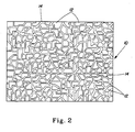
- Webs according to the present invention may have protrusions formed of virtually any three-dimensional shape, as depicted in Figure 2, and accordingly need not be all of a convex polygonal shape.
- Figure 2 is a plan view of a representative web. 10 which includes protrusions 12 of various geometrical shapes extending upwardly from the plane of the material which are separated by valleys 14, the protrusions having a non-uniform size, shape, and spacing throughout the field of view and forming an amorphous pattern.
- Such a representative configuration is depicted in Figure 1 which depicts the protrusions 12 and vaHeys 14.
- the protrusions need not necessarily be of polygonal shape.
- polygon (and the adjective form “polygonal”) is utilized to refer to a two-dimensional geometrical figure with three or more sides, since a polygon with one or two sides would define a line. Accordingly, triangles, quadrilaterals, pentagons, hexagons, etc. are included within the term “polygon”, as would curvilinear shapes such as circles, ellipses, etc. which would have an infinite number of sides.
- the desired physical properties of the resulting structure will dictate the size, geometrical shape, and spacing of the three-dimensional topographical features as well as the choice of materials and forming techniques.
- deformable three-dimensional protrusions will typically exhibit varying degrees of deformabilty, particularly crushability, depending upon their cross-sectional shape and average equivalent diameter.
- the bending modulus and/or flexibility of the overall web will depend upon the relative proportion of two-dimensional material between three-dimensional protrusions.
- the three-dimensional shape of individual protrusions is believed to play a role in determining both the physical properties of individual protrusions as well as overall web properties.
- crush resistance of protrusions i.e., their ability to resist a deformation by crushing and/or inverting in a direction substantially perpendicular to the plane of the material.
- the crush resistance of a given protrusion depends upon the crush strengths of the individual panel segments which define each facet along the perimeter of the protrusion. The panel segment with the lowest crush strength limits the crush strength of the protrusion, much as the weakest link defines the strength of a length of chain.
- Buckling strengths of individual panels can be increased by introducing curvature to the panel in a plane perpendicular to the crush direction, with buckling strength increasing with decreasing radius of curvature. Buckling strengths of individual panels may also be increased by decreasing the width of the panel for a constant height (i.e., decreasing the aspect ratio).
- application of these principles suggests that protrusions will exhibit generally greater crush resistance as the equality in side length and included angles increases by minimizing the "weakest link" effect. Accordingly, a protrusion with one side substantially longer than the others will be limited in crush strength by the buckling behavior of that longest side. Therefore, crush strength for a given perimeter and given wall thickness would be greater for a protrusion having a greater number of smaller sides and would maximize its crush resistance by having the sides of substantially similar dimensions to minimize the weakest link effect.
- an interlocking polygonal base pattern for the protrusions provides a controllable width and spacing of the valleys between the protrusions so that the area available for contact of the active agent with a target surface may be tailored.
- the use of external polygonal bases from which the sides of the frustums extend upwardly also add a degree of predictability and uniformity to the collapse of the protrusions under compressive forces and also improves the release properties of the formed material from the corresponding forming structure.
- interlocking polygonal shapes with finite numbers of sides can be designed so as to pack closely together and in the limiting sense can be packed such that adjacent sides of adjacent polygons can be in contact along their entire length such that there is no "trapped" free space between corners.
- Such patterns therefore open up the entire possible range of polygon area from nearly 0% to nearly 100%, which may be particularly desirable for certain applications where the low end of free space becomes important for functionality.
- Any suitable method may be utilized to design the interlocking polygonal arrangement of hollow frustums which provides suitable design capability in terms of desirable protrusion size, shape, taper, spacing, repeat distance, etc. Even manual methods of design may be utilized. Such pattern may be imparted to the starting web material in any suitable fashion, including manual methods and methods of individually custom-forming the protrusions.
- the non-nesting attributes may be obtained by designing patterns or structures where the relationship of adjacent cells or structures to one another is specified, as is the overall geometrical character of the cells or structures, but wherein the precise size, shape, and orientation of the cells or structures is non-uniform and non-repeating.
- non-repeating is intended to refer to patterns or structures where an identical structure or shape is not present at any two locations within a defined area of interest. While there may be more than one protrusion of a given size and shape within the pattern or area of interest, the presence of other protrusions around them of non-uniform size and shape virtually eliminates the possibility of an identical grouping of protrusions being present at multiple locations. Said differently, the pattern of protrusions is non-uniform throughout the area of interest such that no grouping of protrusions within the overall pattern will be the same as any other like grouping of protrusions.
- the beam strength of the three-dimensional sheet material will prevent significant nesting of any region of material surrounding a given protrusion even in the event that that protrusion finds itself superimposed over a single matching depression since the protrusions surrounding the single protrusion of interest will differ in size, shape, and resultant center-to-center spacing from those surrounding the other protrusion/depression.
- the first step in generating a pattern for making a three-dimensional forming structure is to establish the dimensions of the desired forming structure. For example, if it is desired to construct a forming structure 8 inches wide and 10 inches long, for optionally forming into a drum or belt as well as a plate, then an X-Y coordinate system is established with the maximum X dimension (X Max ) being 8 inches and the maximum Y dimension (Y Max ) being 10 inches (or vice-versa).
- the next step is to determine the number of "nucleation points" which will become polygons corresponding to the number of protrusions desired within the defined boundaries of the forming structure.
- This number is an integer between 0 and infinity, and should be selected with regard to the average size and spacing of the polygons desired in the finished pattern. Larger numbers correspond to smaller polygons, and vrce-versa.
- a useful approach to determining the appropriate number of nucleation points or polygons is to compute the number of polygons of an artificial, hypothetical, uniform size and shape that would be required to fill the desired forming structure.
- N X M a x Y M a x p o l y g o n s i z e + p o l y g o n s p a c i n g 2
- a random number generator is required for the next step. Any suitable random number generator known to those skilled in the art may be utilized, including those requiring a "seed number" or utilizing an objectively determined starting value such as chronological time. Many random number generators operate to provide a number between zero and one ( 0 - 1 ), and the discussion hereafter assumes the use of such a generator. A generator with differing output may also be utilized if the result is converted to some number between zero and one or if appropriate conversion factors are utilized.
- a computer program is written to run the random number generator the desired number of iterations to generate as many random numbers as is required to equal twice the desired number of "nucleation points" calculated above.
- alternate numbers are multiplied by either the maximum X dimension or the maximum Y dimension to generate random pairs of X and Y coordinates all having X values between zero and the maximum X dimension and Y values between zero and the maximum Y dimension. These values are then stored as pairs of (X,Y) coordinates equal in number to the number of "nucleation points".
- ⁇ (beta).
- the constraint limits the proximity of neighboring nucleation point locations through the introduction of an exclusion distance, E, which represents the minimum distance between any two adjacent nucleation points.
- a Delaunay triangulation is performed as the precursor step to generating the finished polygonal pattern.
- the use of a Delaunay triangulation in this process constitutes a simpler but mathematically equivalent alternative to iteratively "growing" the polygons from the nucleation points simultaneously as circles, as described in the theoretical model above.
- the theme behind performing the triangulation is to generate sets of three nucleation points forming triangles, such that a circle constructed to pass through those three points will not include any other nucleation points within the circle.
- a computer program is written to assemble every possible combination of three nucleation points, with each nucleation point being assigned a unique number (integer) merely for identification purposes.
- the radius and center point coordinates are then calculated for a circle passing through each set of three triangularly-arranged points.
- the coordinate locations of each nucleation point not used to define the particular triangle are then compared with the coordinates of the circle (radius and center point) to determine whether any of the other nucleation points fall within the circle of the three points of interest.
- the constructed circle for those three points passes the test (no other nucleation points falling within the circle), then the three point numbers, their X and Y coordinates, the radius of the circle, and the X and Y coordinates of the circle center are stored. If the constructed circle for those three points fails the test, no results are saved and the calculation progresses to the next set of three points.
- each nucleation point saved as being a vertex of a Delaunay triangle forms the center of a polygon.
- the outline of the polygon is then constructed by sequentially connecting the center points of the circumscribed circles of each of the Delaunay triangles, which include that vertex, sequentially in clockwise fashion. Saving these circle center points in a repetitive order such as clockwise enables the coordinates of the vertices of each polygon to be stored sequentially throughout the field of nucleation points.
- a comparison is made such that any triangle vertices at the boundaries of the pattern are omitted from the calculation since they will not define a complete polygon.
- a network of interlocking shapes is utilized as the design for one web surface of a web of material with the pattern defining the shapes of the bases of the three-dimensional, hollow protrusions formed from the initially planar web of starting material.
- a suitable forming structure comprising a negative of the desired finished three-dimensional structure is created which the starting material is caused to conform to by exerting suitable forces sufficient to permanently deform the starting material.
- a physical output such as a line drawing may be made of the finished pattern of polygons.
- This pattern may be utilized in conventional fashion as the input pattern for a metal screen etching process to form a three-dimensional forming structure suitable for forming the materials of the present invention. If a greater spacing between the polygons is desired, a computer program can be written to add one or more parallel lines to each polygon side to increase their width (and hence decease the size of the polygons a corresponding amount).
- the computer program described above provides as its output a computer graphic (.TIFF) file.
- a photographic negative can be made for use in a photoetching process to etch negative impressions into a base material to correspond to the desired frustum polygonal shapes in the finished web of material.
- the computer output could be tailored to provide the desired information to the forming apparatus to the extent it may differ than for a negative (female) pattern.
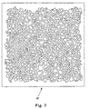
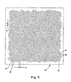
- Figures 3-5 provide plan views of three-dimensional sheet materials 10 constructed utilizing ⁇ values of 0.25, 0.5, and 0.75, respectively.
- a ⁇ value of 0.25 i.e., in the lower end of the range of 0 to 1 yields a much greater variation in the center-to-center spacing of the nucleation points and thus the resulting polygons than does a ⁇ value of 0.75 (i.e., near the higher end of the range of 0 to 1).
- FIG. 1 is a photomicrograph depicting a three-dimensional sheet material formed utilizing a pattern generated with a ⁇ value of 0.75.
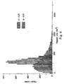
- the polygon area distribution decreases as the constraint ( ⁇ ) is increased.
- the less constrained pattern exhibits a broader range of polygon sizes than the more constrained pattern.
- Both materials were prepared utilizing the above method with a design criteria of 711 polygons per square inch with a spacing between adjacent polygons of 0.015 inches.
- the patterns depicted in Figures 3 and 5 are each a portion of the pattern utilized to generate the data presented in Figure 6.
- the same patterns were utilized for this Figure as were utilized for Figure 6.
- a change in the area of the test box affects the range of % polygon area for a given pattern. As the area of the test box decreases, the variability in % polygon area increases. Conversely, as the area of the test box increases, beyond a certain point the % polygon area remains constant throughout the pattern.
- Figure 5 represents an amorphous two-dimensional pattern generated by the above-described method utilizing a constraint factor of 0.75.
- Material 10 has a plurality of non-uniformly shaped and sized, preferably hollow, protrusions 12, surrounded by spaces or valleys 14 therebetween, which are preferably interconnected to form a continuous network of spaces within the amorphous pattern.
- Figure 5 also shows a dimension A, which represents the width of spaces 14, measured as the substantially perpendicular distance between adjacent, substantially parallel walls at the base of the protrusions.
- the width of spaces 14 is preferably substantially constant throughout the pattern of protrusions.
- Protrusions 12 of the present invention are generated with non-uniform size and shape so that material 10 may be wound onto a roll without nesting occurring between layers of material within the roll.
- the nesting-resistant feature is achieved because the amorphous pattern of the protrusions, as discussed above, limits the ability of the face of one layer to align with the back of another layer whereby the protrusions of one layer enter the depressions formed behind each protrusion in an adjacent layer.
- the benefit of narrow constant-width spaces between protrusions is that protrusions 12 cannot also enter spaces 14 when layers of material 10 are placed face to face.
- Protrusions 14 are preferably spaced center to center an average distance of approximately two protrusion base diameters or closer, in order to minimize the volume of valleys between protrusions and hence the amount of substance located between them.
- the protrusions 14 preferably have heights which are less than their diameters, so that when they deform, they deform by substantially inverting and/or crushing along an axis which is substantially perpendicular to a plane of the material. This protrusion shape and mode of deforming discourages protrusions 14 from folding over in a direction parallel to a plane of the material so that the protrusions cannot block a substance (if present) in the valley between them from contact with a target surface.
- representative protrusion 12 is shown in a representative as-formed condition, while representative protrusion 13 is shown in a deformed condition wherein the upper central portion of the protrusion has been pushed downwardly such that the protrusion has collapsed by substantially inverting upon itself. Such deformation thereby reduces the height of the protrusion without extending outwardly over the adjoining valley or space between protrusions.
- Figures 8 and 9 depict fragmentary elevational cross-sections of material 10 taken at a location where a complete protrusion 12 and both adjoining spaces or valleys 14 can be seen in cross-section.
- Figure 8 depicts the three-dimensional structure of Figure 5 by itself, with no adhesive or other substance added to the basic sheet material.
- the upper surface of the web which faces the viewer of Figure 5, and which includes the projecting portions of the protrusions 12, is identified with the numeral 15, and is referred to hereafter as the male side of the material.
- the lower surface of the web facing away from the viewer of Figure 5, which includes the openings of the hollow portions of the protrusions 12, is identified with the numeral 17, and is referred to hereafter as the female side of the material.
- Figure 9 shows the structure of Figure 5, analogously to Figure 8, but with a substance 16 added to spaces 14, as well as to the hollow underside of the protrusions 12, in accordance with the teachings of commonly-assigned, co-pending, concurrently-filed U.S. Patent Application Serial No. [ ], Attorney's Docket No. Case 5922R, filed November 8, 1996, in the names of Peter W. Hamilton and Kenneth S. McGuire, entitled "Material Having A Substance Protected By Deformable Standoffs and Method of Making", the disclosure of which is hereby incorporated herein by reference.
- Substance 16 partially fills the spaces 14 so that an outer surface of protrusions 12 remain external to the surface level of substance 16 such that the protrusions prevent the substance 16 on the male side of the material from making contact with external surfaces.
- substance 16 partially fills the hollow protrusions such that the reverse side of the valleys or spaces between respective protrusions serves an analogous function in preventing substance 16 within the protrusions from making contact with external surfaces.
- Substances within different sides of the material 10 and/or within different geometrically-distinct zones within a side of material 10 need not be the same substance and could in fact be distinctly different substances serving distinctly different functions.
- “Substance” is defined in this invention as any material capable of being held in open valleys and/or depressions of a three dimensional structure.
- the term “substance” can mean a flowable substance which is substantially non-flowing prior-to delivery to a target surface.
- “Substance” can also mean a material which doesn't flow at all, such as a fibrous or other interlocking material.
- “Substance” may mean a fluid or a solid. Adhesives, electrostatics, mechanical interlocking, capillary attraction, surface adsorption, and friction, for example, may be used to hold the substances in the valleys and/or depressions.
- the substances may be permanently held in the valleys and/or depressions, or the substances may be intended to be released therefrom when exposed to contact with external surfaces or when the three dimensional structure is deformed, heated, or otherwise activated.
- substances such as gels, pastes, foams, powders, agglomerated particles, prills, microencapsulated liquids, waxes, suspensions, liquids, and combinations thereof.
- the spaces in the three-dimensional structure of the present invention are normally open; therefore it is desirable to have substances stay in place and not run out of the structure without an activation step.
- the activation step of the present invention is preferably deformation of the three-dimensional structure by compression.
- an activation step to cause substance to flow could be heating the material to above room temperature or cooling it below room temperature. Or it could include providing forces excessive of the earth's gravity. It could also include other deforming forces, such as tensile forces and combinations of these activation phenomena.
- deformable material is intended to include foils; polymer sheets, cloth, wovens or nonwovens, paper, cellulose fiber sheets, co-extrusions, laminates, and combinations thereof.
- the properties of a selected deformable material can include, though are not restricted to, combinations or degrees of being: porous, nonporous, microporous, gas or liquid permeable, non-permeable, hydrophilic, hydrophobic, hydroscopic, oleophilic, oleophobic, high critical surface tension, low critical surface tension, surface pre-textured, elastically yieldable, plastically yieldable, electrically conductive, and electrically non-conductive.
- Exemplary materials include wood, metal, rigid polymer stock, ceramic, glass, cured resin, thermoset materials, cross-linked materials, rubber, frozen liquids, concrete, cement, stone, man-made materials, etc. Such materials can be homogeneous or composition combinations.
- protrusions 14 have an average base diameter of about 0.015 inches (0.038 cm) to about 0.030 inches (0.076 cm), and more preferably about 0.025 inches (0.064 cm). They also have an average center-to-center spacing of from 0.03 inches (0.08 cm) to 0.06 inches (0.15 cm), and more preferably about 0.05 inches (0.13 cm) spacing. This results in a high number density of protrusions. The more protrusions per unit area, the thinner the piece of material and protrusion walls can be in order to resist a given deformation force. In a preferred embodiment the number of protrusions per square inch exceeds 200 and the protrusions occupy from about 30% to about 70% of the protrusion side of the piece of material.
- the preferred material is 0.0003 inch (0.0076 mm) nominal thickness high density polyethylene (HDPE).
- a preferred layer of substance 16 is preferably a latex pressure sensitive adhesive about 0.001 inch (0.025 mm) thick. Even more preferably, layer of substance 16 may be about 0.0005 inch (0.013 mm) thick layer to about 0.002 inch (0.051 mm) thick layer of hot melt adhesive, specification no. Fuller HL-2115X, made by H. B. Fuller Co. of Vadnais Heights, MN. Any adhesive can be used which suits the needs of the material application. Adhesives may be refastenable, releasable, permanent, or otherwise. The size and spacing of protrusions is preferably selected to provide a continuous adhesive path surrounding protrusions so that air-tight seals may be made with a target surface.
- Film materials may be made from homogeneous resins or blends thereof. Single or multiple layers within the film structure are contemplated, whether coextruded, extrusion-coated, laminated or combined by other known means. The key attribute of the film material is that it be formable to produce protrusions and valleys.
- Useful resins include polyethylene, polypropylene, PET, PVC, PVDC, latex structures, nylon, etc. Polyolefins are generally preferred due to their lower cost and ease of forming.
- Preferred material gauges are about 0.0001 inches (0.0025 mm) to about 0.010 inches (0.25 mm). More preferred gauges are from about 0.0002 inches (0.005 mm) to about 0.002 inches (0.051 mm). Even more preferred gauges are from about 0.0003 inches (0.0076 mm) to about 0.001 inches (0.025 mm).
- Providing a film modulus of elasticity sufficiently high to minimize film stretch during use is beneficial to sealing material 10 to a target surface. Stretched film results in residual forces parallel to the plane of adhesive contact, which may cause a weak adhesive bond to break. The larger and more closely spaced the protrusions, the greater the likelihood of stretch occurring in a given film.
- elasticity in material 10 is believed to be undesirable for use as a container wrap which seals to a container, there are potentially many other uses for an elastic material containing a pattern of substance. Reducing the protrusion spacing to the closest possible spacing which is manufacturable may increase material stretch, but it may be beneficial in reducing the volume of substance between protrusions. Different applications for the formed material of the present invention will dictate ideal size and density of protrusions, as well as the selection of the substances used therewith.
- Beam strength of the three-dimensional sheet material was mentioned above in terms of the beam strength preventing significant nesting of any region of material surrounding a given protrusion even in the event that that protrusion finds itself superimposed over a single matching or larger depression of compatible shape since the protrusions surrounding the single protrusion of interest will differ in size, shape, and spacing from those surrounding the other protrusion/depression. Beam strength is thus an important factor to consider when selecting the material type and thickness, as well as the density and pattern of protrusions. It has been observed that in general larger numbers of smaller protrusions provide a greater level of beam strength for a given material type and thickness than a smaller number of larger protrusions. Said differently, thinner and more conformable materials may be utilized and still realize the non-nesting advantages of the present invention through the use of an amorphous pattern having generally comparatively small, comparatively high number density protrusions.
- the protrusion size, shape and spacing, the web material properties such as flexural modulus, material stiffness, material thickness, hardness, deflection temperature as well as the forming process determine the strength of the protrusion.
- the forming process is important in polymer films for example, since "cold forming" or embossing generates residual stresses and different wall thickness distributions than that produced by thermoforming at elevated temperatures.
- a stiffness deformation resistance
- An example of this requirement would be the need to wind the web onto a roll for transport and/or dispensing.
- the external contact surfaces may be either compliant or rigid and planar or non-planar. Having the three dimensional structure deform is preferred for use with a rigid target surface. If the substance is adhesive and the objective is releasable adherence to a target surface after deformation of the structure, then the degree of adhesion is important. For a storage wrap where releasability after adhesion is necessary, the peel strength of the adhesive is preferably measured by Pressure Sensitive Tape Council Method PSTC-1.
- a 12 inch (30.5 cm) long by 1 inch (2.5 cm) wide strip of film is rolled once against a smooth stainless steel surface at a rate of 12 inches (30.5 cm) per minute using a 4.5 pound (2.04 kg) roller and then tested as having a peak adhesion peel force value ranging from about 1 to about 50 ounces/inch (0.012 to 0.600 kg/cm), more preferably from about 1 to about 2.5 ounces/inch (0.012 to 0.027 kg/cm) of strip width.
- a protrusion's sidewall connects the outermost portion of the protrusion to the unformed material adjacent to base perimeter of the protrusion.
- the sidewall as defined may also contain a peripheral region substantially within the outermost portion which is substantially thinner than the interior region of the outermost portion. Protrusions where at least a portion of the sidewalls are substantially thinner than the unformed material adjacent to the base perimeter are believed preferred for deformation by the user. Sidewalls that are also substantially thinner in at least a portion of the sidewall as compared to the material at the outermost portion of the protrusion also beneficially bias the deformation to occur primarily within the sidewall structure.
- Protrusions 12 have sidewalls 22, which become thinned when protrusions 12 are formed, to help ensure that protrusions 12 deform as intended.
- High density polyethylene is preferred over low density polyethylene because the former can be made thinner for the same protrusion deform strength and because once deformed, HDPE protrusions do not tend to rebound toward their undeformed initial configuration as do the LDPE protrusions.
- Protrusions 12 preferably have a convex polygonal base shape, the formation of which is described hereinafter.
- convex polygonal shape it is meant that the bases of the protrusions have multiple (three or more) linear sides, which form no externally measured angle of less than 180° with any adjacent side.
- alternative base shapes are equally useful. However, the preferred base shape is believed to be most easily generated.
- Polygons preferably interlock in the plane of the lower or female surface 17, as in a tessellation, to provide constant width spacing between them.
- the width A of spaces 14 may be selected depending upon the volume of substance desired between protrusions. Preferably width A is always less than the minimum protrusion dimension of any of plurality of protrusions 12.
- the area occupied by plurality of protrusions 12 is preferably from about 30% to about 70%, more preferably about 50%, of the available area of sheet of material 10, as measured parallel to plane 20.
- Figures 10-13 disclose a suitable method and apparatus for making material 10, the method generally indicated as 30.
- Method 30 is representative and may be modified or tailored to suit a particular size, composition, etc. of the resulting material 10.
- Method 30 utilizes a forming surface 32, which is preferably a three-dimensional screen having recesses 34 and lands 36 between recesses 34.
- a forming structure or forming structure would constitute a female-type forming structure which, in use, would form corresponding male protrusions in the structure-contacting side of the formed material.
- forming surface 32 could comprise a three-dimensional forming structure of the male variety by having raised pins 34 of the desired polygonal shape having recesses 36 between and around the pins 34. In use, such a forming structure would form corresponding female depressions in the structure-contacting side of the formed material.
- Figure 10 depicts a forming surface which could be utilized to form a corresponding three-dimensional material 10 such as depicted in Figure 5.
- protrusions 12 are preferably formed by drawing them into recesses 34 with vacuum when material 10 is heated to a softening temperature, and then maintaining protrusions 12 drawn into recesses 34 while material 10 cools to a solidification temperature.
- lands 36 define the bases of spaces 14 between protrusions 12.
- Protrusions 12 are preferably formed with sidewalls 22 being as nearly perpendicular to plane 20 as possible, but with some taper being typical. Outermost ends of protrusions 12 may domed or more truncated in shape so as to form frustums of the corresponding polygonal shape.
- Material 10 may be vacuum thermoformed, embossed, or hydroformed, or formed by other forming means commonly known in the art for permanently deforming thin materials.
- Figure 10 shows a preferred forming screen 32 comprising interconnected lands 36 surrounding polygonal recesses 34.
- Lands 36 are preferably made of stainless steel and coated with a release agent.
- screen 32 is made into a continuous belt 38, as shown in Figure 13.
- screen 32 could be utilized in flat plate-like form or formed into a rigid drum.
- Figure 12 depicts a partial cross-sectional view of forming screen 32 taken at a location which depicts a cross-section through two consecutive lands.
- Lands 36 have a dimension B which represents the land width, which is preferably constant as measured between substantially parallel adjacent land edges, and a dimension T which represents screen thickness.
- Figure 11 is a photomicrograph depicting a perspective view of a representative three-dimensional forming structure 32 having recesses 34 and lands 36 suitable for forming a three-dimensional, nesting-resistant sheet material such as that of Figure 1.
- Methods of production can influence the sidewall thickness profile such as in the use of a forming screen with essentially straight screen walls which define the forming screen hole.
- Such a process allows for substantially thinner sidewall thickness since the protrusion is freely drawn from the base perimeter into the forming screen recess to the point of contact with the internal backup screen.
- the internal backup screen's purpose is to prevent further drawing of the protrusion. This approach yields a more varied gauge profile within the sidewalls.
- thermoforming behaves differently than when other substances are processed.
- protrusions which are formed when hot melt adhesive has been applied to the forming surface, tend to exhibit more thinning in their sidewalls.
- the hot melt adhesive cools and solidifies when contacting the metal forming surface and thereby prevents web material in contact with the adhesive from being drawn into the recesses, so that uniform thickness valleys result.
- other substances such as latex adhesive, less thinning of protrusion sidewalls occurs, presumably because some of the web material in contact with the adhesive on the lands or pin tops of the forming surface flows into the recesses during thermoforming.
- Figure 13 shows a suitable and presently preferred method and apparatus for making a material such as material 10 of the present invention, which is generally indicated as 180.
- the formed material is preferably transparent or translucent, so that it may be accurately positioned before being deformed. Transparency, however, introduces a new problem of determining on which side of the three-dimensional structure the substance is located, in order to know which side to place against a target surface.
- Substance side identification can be solved by placing indicia on the surface of the three dimensional structure, by coloring the substance a different tint than the three dimensional structure, or by providing a laminated material structure of different tints, for example. In the case of labels, transparency may not be needed since material edges may be used for proper positioning.
- Micro-texturing the material during forming may also be useful, such as in producing a distinction between one side of the material and the other side.
- Micro-texturing of the outermost surface features of the three dimensional structure may be achieved in the present invention, for example, by drawing the piece of material into forming screen recesses and against a micro-textured surface, such as a vacuum drum having tiny apertures therein.
- Forming screen 181 is threaded over idler pulley 182 and a driven vacuum roll 184.
- Forming screen 181 is preferably a 0.005 inch (0.013 cm) thick, 12.5 inch (31.8 cm) wide, 6 foot (183 cm) circumference stainless steel belt, having the desired protrusion pattern etched as recesses in the belt.
- Covering the outer surface of vacuum roll 184 is a 195 mesh seamless nickel screen having a diameter of 8.63 inches (21.9 cm), which serves as a porous backing surface for forming screen 181.
- a substance 186 preferably hot melt adhesive
- a substance applicator 188 For producing a pressure sensitive adhesive containing material, a substance 186, preferably hot melt adhesive, is coated onto forming screen 181 by a substance applicator 188 while forming screen 181 travels at about 20 feet (610 cm) per minute.
- a material 190 for example, a HDPE film web about 0:0005 inches (0.0013 cm) thick, is brought into contact with the substance-coated forming screen at material infeed idler roll 192.
- Hot air at approximately 600°F (316°C) and flowing at approximately 11.25 SCFM (0.32 cubic meters/minute) is directed radially at material 190 by a hot air source 194 as the material passes over vacuum roll 184 and as vacuum is applied to forming screen 181 through vacuum roll 184 via fixed vacuum manifold 196 from a vacuum source (not shown).
- a vacuum of approximately 12 inches of mercury (40.6 kPa) is applied as the material is heated by hot air source 194.
- a formed, substance coated material 198 is stripped from forming screen 181 at stripping roll 200.
- Stainless steel forming screen 181 is a fabricated, seamed belt. It is fabricated in several steps.
- the recess pattern is preferably developed by a computer program according to the method described above and is preferably printed onto a transparency to provide a photomask for photoetching.
- the photomask is used to create etched and non-etched areas.
- the etched material is typically stainless steel, but it may also be brass, aluminum, copper, magnesium, and other materials including alloys.
- Methods of making metal screens by photoetching are described in more detail in commonly owned U.S. Patent Nos. 4,342,314 to Radel and Thompson, 4,508,256 to Radel et al., and 4,509,908 to Mullane, Jr., the disclosures of which are hereby incorporated herein by reference.
- the recess pattern may be etched into photosensitive polymers instead of metals. Examples are described along with a methods of making polymer forming screens in commonly owned U.S. Patent Nos. 4,514,345 to Johnson et al., 5,098,522 to Smurkoski et al., 4,528,239 to Trokhan, and 5,245,025 to Trokhan, the disclosures of which are hereby incorporated herein by reference.
- the forming screen is converted into a continuous belt by butt welding the ends together, using either laser or electron beam welding. This produces a nearly undetectable seam, which is needed to minimize disruptions in the recess pattern.
- the final step is coating the endless belt with a low critical surface tension (non-stick) coating, such as a Series 21000 proprietary release coating made by and applied by Plasma Coatings of TN, Inc., located in Memphis, TN. It is believed that this coating is primarily an organo-silicone epoxy. As applied to a stainless steel forming screen used in the methods of the present invention, this coating provides a critical surface tension of about 18 dynes/cm. Other materials which may prove suitable for providing reduced critical surface tension include paraffins, silicones, PTFE's, and the like. This coating allows the formed material to be removed from the belt without undue stretching or tearing.
- a belt forming screen is believed advantageous to a flat plate or a drum forming screen because a belt enables screen patterns and pattern lengths to be changed more easily and larger patterns may be used without having massive rotating members.
- the material 10 to be formed it may be equally suitable to fabricate the forming structure as a flat plate or rigid drum, and/or other forming structures and methods known in the art.
- the substance pattern is conveniently registered with the protrusions.
- the top surface of forming screen 32 is continuous except for recesses 34; thus, the substance pattern is totally interconnected in this configuration.
- a discontinuous pattern of substance were coated onto forming screen 32, a discontinuous substance pattern between protrusions would result.
- the three-dimensional protrusions are unitarily formed from the sheet of deformable material itself and are hollow structures with depressions in one side which preferably each have a size and three-dimensional shape corresponding substantially with the size and three-dimensional shape of their respective protrusion.
- solid protrusions may also be desirable for some applications to utilize solid protrusions unitarily, integrally, or separately formed from (and applied to) the sheet of material and which may or may not be deformable.
- the present invention is a three-dimensional, amorphous-patterned, nesting-resistant sheet material which is suitable for holding a substance protected from inadvertent contact with external surfaces.
- the sheet material of the present invention may be utilized as part of a structure which is convertible to a substantially two-dimensional structure by applying a compressive force so that the structure collapses to release or expose the substance into contact with external surface(s).
- the scope of the invention also applies to three-dimensional structures holding substances from inadvertent contact, which are converted to substantially two dimensional structures by means other than compression.
- a tensile force applied to the same three-dimensional structure can cause it to plastically deform longitudinally and thereby contract in caliper or thickness to similarly expose or release substance.
- protrusions deforms in response to forces in the plane of the material and that protrusions are thereby elongated in the same direction.
- protrusions are elongated, they are reduced in height. With enough elongation the protrusions are reduced in height to where the substances between them, in them, or both are exposed.
- a one inch wide strip of material 10 made from 0.0003 inch (0.0076 mm) thick HDPE and formed to have protrusions of 0.006 inches (0.152 mm) height and 0.030 inches (0.762 mm) diameter, spaced 0.045 inches (1.14 mm) apart, the tensile force found necessary to cause protrusions to expose a 0.001 inch (0.025 mm) thick coating of adhesive in the valleys between protrusions is approximately 0.80 pounds (0.36 kg) per inch of strip width.
- a combination of compression and tensile forces may be applied to the material of the present invention in order to expose a substance from within the three-dimensional structure.
- the tensile force necessary to achieve sufficient deformation of said three-dimensional structure in order to expose substance to an external surface is significantly greater than a compressive force to achieve the same result, a structure may be designed which is more easily deformed by a tensile force applied in a specific planar direction.
- Tensile responsive structures and the principles behind them are disclosed in commonly-assigned U.S. Patent No. 5,518,801 to Chappell et al., the disclosure of which is hereby incorporated herein by reference.
- heat could be applied to cause the same structure made of shrinkable film to reduce in thickness to similarly release or expose the substance.
- Examples of uses of the three-dimensional sheet materials of the present invention besides tapes, labels, and storage wraps include: lotion impregnated facial tissues, scented strips containing microencapsulated perfumes, adhesive impregnated shelf and wall paper, medicinal patches, patterned condiment delivery to a surface, two component adhesives, laundry pre-treating chemicals, abrasive delivery systems, and other applications where avoidance of contact with a substance held in a substrate is desired until some action is taken.
- Alternative uses of a material having a three dimensional structure which may be converted to a two dimensional structure in order to expose a substance are described in more detail in the aforementioned and incorporated commonly-assigned, co-pending, concurrently-filed U.S. Patent Application Serial No. [ ], Attorney's Docket No. Case 5922R.
- different substances can be deposited on the opposing faces of the formed material. Multiple substances can be located on the same face of the material either geometrically spaced from each other or commingled. Substances can be partially layered. An example is a layer of adhesive adjacent to the material surface with a solid particulate adhered to the exposed side of the adhesive layer. In addition, it is contemplated that it may be desirable for certain applications to have protrusions extending outwardly from both sides of the formed material, such that both sides are active sides with deformable protrusions.
- a pattern of protrusions can be superimposed either on a similar dimensional scale or on a different dimensional scale such as a single or multiple "microprotrusion" pattern located on the tops of other larger protrusions.
- three-dimensional sheet materials containing a substance in addition to the material from which the sheet itself is formed such as a pressure-sensitive adhesive
- three-dimensional sheet materials containing no such additional substance are to be considered within the scope of the present invention.
- a three-dimensional spacing sheet for use as a packaging wrap may be formed and utilized to fill voids within a shipping container such that an item enclosed therein may be essentially immobilized.
- Another example of such a three-dimensional sheet material is in the category of cleansing and cleaning implements such as wipes, cloths, sponges, pads, etc.
- the channels within the three-dimensional structure are employed to collect, imbibe, or scoop up dirt, solids, free liquids, or combinations thereof during cleaning and cleansing tasks.
- the amorphous pattern of-channels or depressions provides for efficient cleaning due to some of the pattern's advantageous properties. This allows for effective cleaning irrespective of wiping direction and/or the chosen portion of the pattern which contacts the surface or item to be cleaned.
- a substance can be included in the three-dimensional sheet material before use which may deliver advantageous cleaning or cleansing properties.
Landscapes
- Engineering & Computer Science (AREA)
- Mechanical Engineering (AREA)
- Laminated Bodies (AREA)
- Blow-Moulding Or Thermoforming Of Plastics Or The Like (AREA)
- Woven Fabrics (AREA)
- Treatment Of Fiber Materials (AREA)
- Shaping Of Tube Ends By Bending Or Straightening (AREA)
- Soft Magnetic Materials (AREA)
- Battery Electrode And Active Subsutance (AREA)
Applications Claiming Priority (3)
| Application Number | Priority Date | Filing Date | Title |
|---|---|---|---|
| US08/745,339 US5965235A (en) | 1996-11-08 | 1996-11-08 | Three-dimensional, amorphous-patterned, nesting-resistant sheet materials and method and apparatus for making same |
| PCT/US1997/000201 WO1998021410A1 (en) | 1996-11-08 | 1997-01-08 | Three-dimensional, amorphous-patterned, nesting-resistant sheet materials and method and apparatus for making same |
| US745339 | 2000-12-22 |
Publications (2)
| Publication Number | Publication Date |
|---|---|
| EP0937180A1 EP0937180A1 (en) | 1999-08-25 |
| EP0937180B1 true EP0937180B1 (en) | 2006-11-29 |
Family
ID=24996292
Family Applications (1)
| Application Number | Title | Priority Date | Filing Date |
|---|---|---|---|
| EP97901373A Expired - Lifetime EP0937180B1 (en) | 1996-11-08 | 1997-01-08 | Three-dimensional, amorphous-patterned, nesting-resistant sheet materials and method and apparatus for making same |
Country Status (27)
| Country | Link |
|---|---|
| US (2) | US5965235A (ko) |
| EP (1) | EP0937180B1 (ko) |
| JP (1) | JP4531134B2 (ko) |
| KR (1) | KR100314984B1 (ko) |
| CN (2) | CN1119460C (ko) |
| AR (1) | AR005442A1 (ko) |
| AT (1) | ATE346977T1 (ko) |
| AU (1) | AU731961B2 (ko) |
| BR (1) | BR9713497A (ko) |
| CA (1) | CA2271083C (ko) |
| CO (1) | CO4650059A1 (ko) |
| CZ (1) | CZ301490B6 (ko) |
| DE (1) | DE69737027T2 (ko) |
| EG (1) | EG21617A (ko) |
| ES (1) | ES2277351T3 (ko) |
| HK (1) | HK1022178A1 (ko) |
| HU (1) | HUP0000594A3 (ko) |
| ID (1) | ID18828A (ko) |
| IL (1) | IL129716A (ko) |
| MA (1) | MA24052A1 (ko) |
| MY (1) | MY115062A (ko) |
| NO (1) | NO992216L (ko) |
| PE (1) | PE39098A1 (ko) |
| TR (1) | TR199900987T2 (ko) |
| TW (1) | TW401347B (ko) |
| WO (1) | WO1998021410A1 (ko) |
| ZA (1) | ZA97164B (ko) |
Families Citing this family (133)
| Publication number | Priority date | Publication date | Assignee | Title |
|---|---|---|---|---|
| CA2255599C (en) | 1996-04-25 | 2006-09-05 | Bioarray Solutions, Llc | Light-controlled electrokinetic assembly of particles near surfaces |
| US5965235A (en) * | 1996-11-08 | 1999-10-12 | The Procter & Gamble Co. | Three-dimensional, amorphous-patterned, nesting-resistant sheet materials and method and apparatus for making same |
| US5968633A (en) * | 1997-06-06 | 1999-10-19 | The Procter & Gamble Company | Selectively-activatible sheet material for dispensing and dispersing a substance onto a target surface |
| US6099940A (en) * | 1997-07-16 | 2000-08-08 | The Procter & Gamble Company | Selectively-activatible three-dimensional sheet material having multi-stage progressive activation to deliver a substance to a target surface |
| US6612473B1 (en) * | 1999-03-11 | 2003-09-02 | The Procter & Gamble Company | Asymmetrical end-loadable carton for rolled sheet materials |
| US6148496A (en) * | 1999-04-09 | 2000-11-21 | The Procter & Gamble Company | Method for making a seamless apertured metal belt |
| US6421052B1 (en) | 1999-04-09 | 2002-07-16 | The Procter & Gamble Company | Method of seaming and expanding amorphous patterns |
| US6270878B1 (en) * | 1999-05-27 | 2001-08-07 | The Procter & Gamble Company | Wipes having a substrate with a discontinous pattern of a high internal phase inverse emulsion disposed thereon and process of making |
| CA2377401A1 (en) | 1999-06-18 | 2000-12-28 | The Procter & Gamble Company | Multi-purpose absorbent and cut-resistant sheet materials |
| US6274232B1 (en) | 1999-06-18 | 2001-08-14 | The Procter & Gamble Company | Absorbent sheet material having cut-resistant layer and method for making the same |
| US6592983B1 (en) | 1999-06-18 | 2003-07-15 | The Procter & Gamble Company | Absorbent sheet material having cut-resistant particles and methods for making the same |
| US6451410B1 (en) | 1999-06-18 | 2002-09-17 | The Procter & Gamble Company | Flexible, cut resistant, and abrasion resistant sheet material and method for making same |
| US6443936B1 (en) * | 1999-08-06 | 2002-09-03 | The Procter & Gamble Company | Absorbent article having improved adhesive system to provide flexibility and breathability |
| US6299966B1 (en) * | 1999-09-24 | 2001-10-09 | Reynolds Metals Company | Embossed cling wrap |
| US6394299B1 (en) | 2000-01-11 | 2002-05-28 | The Procter & Gamble Company | Slider for opening or closing a reclosable fastener disposed in a two dimensional plane |
| US20020042962A1 (en) * | 2000-02-24 | 2002-04-18 | Willman Kenneth William | Cleaning sheets comprising a polymeric additive to improve particulate pick-up and minimize residue left on surfaces and cleaning implements for use with cleaning sheets |
| US6858285B1 (en) | 2000-03-22 | 2005-02-22 | The Procter & Gamble Company | High bond strength, repositionable adherent sheet |
| GB0008538D0 (en) * | 2000-04-06 | 2000-05-24 | Itw Ltd | Protective packaging sheet |
| ES2509871T3 (es) * | 2000-04-07 | 2014-10-20 | The Procter & Gamble Company | Bandas de película polimérica con orificios y artículos absorbentes que utilizan tales bandas |
| AU2000248359A1 (en) | 2000-05-11 | 2001-11-20 | The Procter And Gamble Company | Releasably sealable bags and methods for food preparation |
| WO2001085562A1 (en) | 2000-05-11 | 2001-11-15 | The Procter & Gamble Company | Releasably sealable bag comprising a composite sheet material |
| US20030118759A1 (en) * | 2000-05-11 | 2003-06-26 | The Procter & Gamble Company | Releasably sealable bag comprising a composite sheet material |
| AU2001272993B2 (en) | 2000-06-21 | 2005-03-10 | Bioarray Solutions, Ltd. | Multianalyte molecular analysis |
| US9709559B2 (en) | 2000-06-21 | 2017-07-18 | Bioarray Solutions, Ltd. | Multianalyte molecular analysis using application-specific random particle arrays |
| US20040192133A1 (en) * | 2000-07-06 | 2004-09-30 | Higher Dimension Medical, Inc. | Abrasion and heat resistant fabrics |
| FR2811316B1 (fr) * | 2000-07-06 | 2003-01-10 | Saint Gobain | Substrat texture transparent et procedes pour l'obtenir |
| US20030124935A1 (en) * | 2000-07-06 | 2003-07-03 | Nicole Smith | Scrub pad with printed rigid plates and associated methods |
| NZ523750A (en) | 2000-07-24 | 2004-10-29 | S | Pressure sensitive food grade wrap film and process for manufacturing such a film |
| EP1311392B1 (en) * | 2000-07-31 | 2004-12-15 | Reynolds Metals Company | Plastic wrap with cling layer |
| US6409615B1 (en) | 2000-08-15 | 2002-06-25 | The Procter & Gamble Company | Golf ball with non-circular shaped dimples |
| US6610173B1 (en) | 2000-11-03 | 2003-08-26 | Kimberly-Clark Worldwide, Inc. | Three-dimensional tissue and methods for making the same |
| US20020078665A1 (en) | 2000-12-21 | 2002-06-27 | Salman Nabil Enrique | Portable packaging device and method for forming individually packaged articles |
| US6541098B2 (en) | 2000-12-22 | 2003-04-01 | Avery Dennison Corporation | Three-dimensional flexible adhesive film structures |
| US6660352B2 (en) | 2001-01-09 | 2003-12-09 | 3M Innovative Properties Company | Adhesive electrostatic sheets |
| US7262063B2 (en) | 2001-06-21 | 2007-08-28 | Bio Array Solutions, Ltd. | Directed assembly of functional heterostructures |
| US20030003831A1 (en) * | 2001-06-29 | 2003-01-02 | Childs Stephen Lee | Cleaning sheets comprising multi-denier fibers |
| US20030003832A1 (en) * | 2001-06-29 | 2003-01-02 | The Procter & Gamble Company | Cleaning sheets comprising a fibrous web of carded staple fibers hydroentangled with a reinforcing fibrous web |
| TW567392B (en) * | 2001-09-07 | 2003-12-21 | Nec Corp | Device for generating ragged pattern data in random arrangement, computer program, mask and manufacturing device, light reflection member manufacturing device, liquid crystal manufacturing device, liquid crystal display device, portable terminal device |
| CA2741049C (en) | 2001-10-15 | 2019-02-05 | Bioarray Solutions, Ltd. | Multiplexed analysis of polymorphic loci by probe elongation-mediated detection |
| US6881471B2 (en) * | 2001-10-25 | 2005-04-19 | The Procter & Gamble Company | High speed embossing and adhesive printing process and apparatus |
| US20030082345A1 (en) * | 2001-10-25 | 2003-05-01 | Hamilton Peter Worthington | Storage wrap material |
| WO2003037768A2 (en) * | 2001-10-26 | 2003-05-08 | The Procter & Gamble Company | Flexible wrap kit and methods |
| JP4275532B2 (ja) * | 2001-10-26 | 2009-06-10 | ザ プロクター アンド ギャンブル カンパニー | 被覆システム |
| US7235156B2 (en) * | 2001-11-27 | 2007-06-26 | Kimberly-Clark Worldwide, Inc. | Method for reducing nesting in paper products and paper products formed therefrom |
| US7490730B2 (en) | 2001-11-29 | 2009-02-17 | The Procter & Gamble Company | Container including a slider, a reclosable fastener and a track including a ramp |
| US7001475B2 (en) * | 2001-12-11 | 2006-02-21 | 3M Innovative Properties Company | Film structures and methods of making film structures |
| US20030121586A1 (en) * | 2001-12-11 | 2003-07-03 | 3M Innovative Properties Company | Tack-on-pressure films for temporary surface protection and surface modification |
| US20030171051A1 (en) * | 2002-03-08 | 2003-09-11 | 3M Innovative Properties Company | Wipe |
| USD472948S1 (en) | 2002-04-22 | 2003-04-08 | The Procter & Gamble Company | Golf ball |
| US8696749B2 (en) * | 2002-04-25 | 2014-04-15 | Blackstone Medical, Inc. | Artificial intervertebral disc |
| JP2005524780A (ja) * | 2002-05-02 | 2005-08-18 | ポリマー・グループ・インコーポレーテツド | 低下した表面閉塞を示す清掃用品 |
| US6699347B2 (en) * | 2002-05-20 | 2004-03-02 | The Procter & Gamble Company | High speed embossing and adhesive printing process |
| US6846172B2 (en) * | 2002-06-07 | 2005-01-25 | The Procter & Gamble Company | Embossing apparatus |
| US7000864B2 (en) | 2002-06-10 | 2006-02-21 | The Procter & Gamble Company | Consumer product winding control and adjustment |
| US20040007494A1 (en) * | 2002-07-15 | 2004-01-15 | Popeil Ronald M. | Apparatus and method to more effectively vacuum package foods and other objects |
| US20040137202A1 (en) * | 2002-10-25 | 2004-07-15 | The Procter & Gamble Company | Multifunctional adhesive food wraps |
| US7526114B2 (en) | 2002-11-15 | 2009-04-28 | Bioarray Solutions Ltd. | Analysis, secure access to, and transmission of array images |
| US7004632B2 (en) | 2003-03-31 | 2006-02-28 | The Glad Products Company | Ventable storage bag |
| WO2004104172A2 (en) * | 2003-05-15 | 2004-12-02 | Bioarray Solutions, Ltd. | Hybridization-mediated analysis of polymorphisms |
| US20050005504A1 (en) * | 2003-06-30 | 2005-01-13 | Munagavalasa Murthy S. | Volatile insect control sheet and method of manufacture thereof |
| US7927796B2 (en) | 2003-09-18 | 2011-04-19 | Bioarray Solutions, Ltd. | Number coding for identification of subtypes of coded types of solid phase carriers |
| AU2004276761B2 (en) | 2003-09-22 | 2009-12-24 | Bioarray Solutions, Ltd. | Surface immobilized polyelectrolyte with multiple functional groups capable of covalently bonding to biomolecules |
| JP2007521017A (ja) | 2003-10-28 | 2007-08-02 | バイオアレイ ソリューションズ リミテッド | 固定化捕捉プローブを用いる遺伝子発現分析法の最適化 |
| WO2005045060A2 (en) | 2003-10-29 | 2005-05-19 | Bioarray Solutions, Ltd. | Multiplexed nucleic acid analysis by fragmentation of double-stranded dna |
| US20060188710A1 (en) * | 2004-02-04 | 2006-08-24 | Windorski David C | Pad with selectively activated adhesive |
| US7326453B2 (en) * | 2004-02-04 | 2008-02-05 | 3M Innovative Properties Company | Article with selectively activated adhesive |
| WO2005085527A1 (en) * | 2004-03-04 | 2005-09-15 | Sca Hygiene Products Ab | A multi-ply tissue paper |
| US20050276953A1 (en) * | 2004-06-14 | 2005-12-15 | 3M Innovative Properties Company | Selective adhesive gift wrapping sheet |
| US20050276971A1 (en) * | 2004-06-14 | 2005-12-15 | 3M Innovative Properties Company | Selective adhesive gift wrapping sheet and method for using same |
| US20050286817A1 (en) * | 2004-06-28 | 2005-12-29 | Hall Bruce N | Storage bag |
| US7848889B2 (en) | 2004-08-02 | 2010-12-07 | Bioarray Solutions, Ltd. | Automated analysis of multiplexed probe-target interaction patterns: pattern matching and allele identification |
| BRPI0514581A (pt) * | 2004-08-26 | 2008-06-17 | 3M Innovative Properties Co | método de proteger um substrato |
| US8486629B2 (en) | 2005-06-01 | 2013-07-16 | Bioarray Solutions, Ltd. | Creation of functionalized microparticle libraries by oligonucleotide ligation or elongation |
| US8911850B2 (en) * | 2005-06-08 | 2014-12-16 | The Procter & Gamble Company | Amorphous patterns comprising elongate protrusions for use with web materials |
| US7829177B2 (en) * | 2005-06-08 | 2010-11-09 | The Procter & Gamble Company | Web materials having offset emboss patterns disposed thereon |
| US7374639B2 (en) * | 2005-06-08 | 2008-05-20 | The Procter & Gamble Company | Papermaking belt |
| JP2007022000A (ja) * | 2005-07-20 | 2007-02-01 | Honda Motor Co Ltd | 物体の表面構造 |
| US20070022606A1 (en) * | 2005-07-29 | 2007-02-01 | Mcguire Kenneth S | Shaving foil |
| US7845079B2 (en) * | 2005-07-29 | 2010-12-07 | The Gillette Company | Shaving foil |
| US20090029156A1 (en) * | 2005-08-11 | 2009-01-29 | Kruchko Steven N | Substrate having polarized adhesive |
| US20070035215A1 (en) * | 2005-08-11 | 2007-02-15 | Kruchko Steven N | Substrate having polarized adhesive |
| US20070178262A1 (en) * | 2006-01-27 | 2007-08-02 | The Procter & Gamble Company | Storage wrap material |
| US7651579B1 (en) | 2006-01-27 | 2010-01-26 | The Glad Products Company | Storage bag |
| US7712962B1 (en) | 2006-01-27 | 2010-05-11 | The Glad Produts Company | Storage bag |
| ATE432125T1 (de) * | 2006-02-09 | 2009-06-15 | Hoffmann La Roche | Auf 2d-substraten basierende 3d-strukturen |
| MX2008011678A (es) * | 2006-03-23 | 2008-10-31 | Procter & Gamble | Aparato y proceso para limpiar superficies de procesos. |
| TWI400142B (zh) * | 2006-07-28 | 2013-07-01 | Toray Industries | 相互侵入高分子網目構造體及研磨墊與其製法 |
| DE102006052622A1 (de) * | 2006-11-08 | 2008-05-15 | Braun Gmbh | Scherfolie für einen elektrischen Rasierapparat |
| US20080115463A1 (en) * | 2006-11-17 | 2008-05-22 | Ramona Wilson | Diaper wrapping methods, apparatus, and systems |
| US8234940B2 (en) * | 2006-11-20 | 2012-08-07 | Duval Joelle N | Trace evidence collection method |
| US20080179330A1 (en) * | 2007-01-29 | 2008-07-31 | Brooks Kerry G | Trash containment system |
| AU2008245845A1 (en) | 2007-04-24 | 2008-11-06 | Convatec Technologies Inc. | Closure system for a drainable pouch |
| KR101161490B1 (ko) | 2007-06-06 | 2012-07-12 | 하이어 디멘션 머티리얼즈, 인크. | 절단, 마멸 및/또는 관통 내성을 가진 니트 장갑 |
| US7874731B2 (en) | 2007-06-15 | 2011-01-25 | S.C. Johnson Home Storage, Inc. | Valve for a recloseable container |
| US7967509B2 (en) | 2007-06-15 | 2011-06-28 | S.C. Johnson & Son, Inc. | Pouch with a valve |
| US20090126320A1 (en) | 2007-11-16 | 2009-05-21 | Playtex Products, Inc. | Waste disposal devices and methods |
| US8613371B2 (en) * | 2007-11-16 | 2013-12-24 | Eveready Battery Company, Inc. | Waste disposal devices for storage of waste in an inner storage area and methods |
| JP4921419B2 (ja) * | 2008-06-03 | 2012-04-25 | Sriスポーツ株式会社 | ゴルフボール表面の凹凸パターン設計方法 |
| JP4921442B2 (ja) * | 2008-10-08 | 2012-04-25 | Sriスポーツ株式会社 | ゴルフボール表面の凹凸パターン設計方法 |
| US8765217B2 (en) | 2008-11-04 | 2014-07-01 | Entrotech, Inc. | Method for continuous production of (meth)acrylate syrup and adhesives therefrom |
| JP2010213741A (ja) * | 2009-03-13 | 2010-09-30 | Sri Sports Ltd | ゴルフボール |
| US8329079B2 (en) | 2009-04-20 | 2012-12-11 | Entrochem, Inc. | Method and apparatus for continuous production of partially polymerized compositions and polymers therefrom |
| US8298376B2 (en) * | 2010-08-19 | 2012-10-30 | The Procter & Gamble Company | Patterned framework for a papermaking belt |
| US8211271B2 (en) | 2010-08-19 | 2012-07-03 | The Procter & Gamble Company | Paper product having unique physical properties |
| US8313617B2 (en) * | 2010-08-19 | 2012-11-20 | The Procter & Gamble Company | Patterned framework for a papermaking belt |
| JP4993640B2 (ja) * | 2011-05-26 | 2012-08-08 | ダンロップスポーツ株式会社 | ゴルフボール表面の凹凸パターン設計方法 |
| JP4993639B2 (ja) * | 2011-05-26 | 2012-08-08 | ダンロップスポーツ株式会社 | ゴルフボール表面の凹凸パターン設計方法 |
| JP5425139B2 (ja) * | 2011-06-30 | 2014-02-26 | ダンロップスポーツ株式会社 | ゴルフボール表面の凹凸パターン設計方法 |
| EP2758232A2 (en) | 2011-09-20 | 2014-07-30 | Avery Dennison Corporation | Embossed thermoplastic label |
| DE102012204559A1 (de) * | 2012-03-22 | 2013-09-26 | BSH Bosch und Siemens Hausgeräte GmbH | Haushaltsgerät mit einem Prägemuster |
| US9194119B2 (en) | 2012-10-04 | 2015-11-24 | ST Global Partners, LLC | Peel and stick decoupling membrane |
| PL2908798T3 (pl) | 2012-10-17 | 2019-02-28 | Procter & Gamble | Pasek do wprowadzania środka aktywującego higienę jamy ustnej i sposoby stosowania środków aktywujących higienę jamy ustnej |
| EP2914488A4 (en) * | 2012-11-01 | 2016-06-29 | Israel Aerospace Ind Ltd | MANUFACTURE OF INTEGRATED STRUCTURES MADE FROM COMPOSITE MATERIALS |
| EP2738742B1 (en) * | 2012-11-07 | 2018-07-25 | Sumitomo Rubber Industries, Ltd. | Process for designing rugged pattern on golf ball surface |
| JP6127319B2 (ja) | 2014-03-13 | 2017-05-17 | 特種東海製紙株式会社 | ガラス合紙 |
| US20150272401A1 (en) * | 2014-03-25 | 2015-10-01 | The Procter & Gamble Company | Fibrous structures |
| WO2015177586A1 (en) | 2014-05-20 | 2015-11-26 | Essilor International (Compagnie Generale D'optique) | Optical lens coated with a patterned removable film and method for edging such a lens |
| WO2016093849A1 (en) | 2014-12-12 | 2016-06-16 | Bemis Company, Inc. | Flexible package with embossed liquid containment cells |
| USD793097S1 (en) * | 2015-01-13 | 2017-08-01 | Giuseppe Dinunzio | Plastic sheet material |
| US10168629B2 (en) * | 2015-01-19 | 2019-01-01 | Hp Indigo B.V. | Liquid electrophotographic varnish composition |
| US10532541B2 (en) * | 2015-04-15 | 2020-01-14 | Sekisui Chemical Co., Ltd. | Intermediate film for laminated glass, and laminated glass |
| JP6929838B2 (ja) | 2015-10-14 | 2021-09-01 | コンバテック・テクノロジーズ・インコーポレイテッドConvatec Technologies Inc | 開口システムを有する医療装置 |
| WO2017067799A1 (en) | 2015-10-23 | 2017-04-27 | Unilever Plc | A resilient body comprising a corrugated surface |
| KR101766997B1 (ko) | 2016-02-15 | 2017-08-23 | 한양대학교 산학협력단 | 3차원 음향 확산 구조체 및 이의 설계 시스템 |
| USD850124S1 (en) * | 2016-05-25 | 2019-06-04 | Bobst Mex Sa | Packaging substrate with surface pattern |
| DE102017004000A1 (de) * | 2017-04-26 | 2018-10-31 | Ewald Dörken Ag | Entkopplungsbahn |
| DE102017004002A1 (de) * | 2017-04-26 | 2018-10-31 | Ewald Dörken Ag | Entkopplungsbahn |
| USD880170S1 (en) * | 2017-10-24 | 2020-04-07 | Bedgear, Llc | Fabric |
| USD880169S1 (en) * | 2017-10-24 | 2020-04-07 | Bedgear, Llc | Fabric |
| US10885233B2 (en) | 2018-04-23 | 2021-01-05 | Milliken & Company | Systems and methods for generating textiles with repeating patterns |
| US11702797B2 (en) | 2020-03-16 | 2023-07-18 | Gpcp Ip Holdings Llc | Tissue products formed from multi-apex emboss elements and methods for producing the same |
| US11441274B2 (en) | 2020-03-16 | 2022-09-13 | Gpcp Ip Holdings Llc | Tissue products having emboss elements with reduced bunching and methods for producing the same |
| DE102020134732A1 (de) * | 2020-12-22 | 2022-06-23 | Liebherr-Hausgeräte Ochsenhausen GmbH | Thermoformteil |
Family Cites Families (106)
| Publication number | Priority date | Publication date | Assignee | Title |
|---|---|---|---|---|
| BE570960A (ko) * | ||||
| US2338749A (en) * | 1942-03-17 | 1944-01-11 | Ralph H Wilbur | Tie band, label, and similar article |
| US2861006A (en) * | 1957-02-19 | 1958-11-18 | Scholl Mfg Co Inc | Adhesive tape and method of making the same |
| FR1315903A (fr) * | 1961-12-14 | 1963-01-25 | Nouveau matériau d'emballage | |
| GB975783A (en) * | 1962-07-16 | 1964-11-18 | Us Rubber Co | Method of making an article of a polymeric resin having co-ordinated surface relief and colouring |
| US3312005A (en) * | 1962-10-04 | 1967-04-04 | Dennison Mfg Co | Linerless pressure-sensitive labels |
| FR1376509A (fr) * | 1963-05-02 | 1964-10-31 | Procédé de collage pour emballage de beurre | |
| US3386846A (en) * | 1963-06-19 | 1968-06-04 | Nashua Corp | Activatable adhesive sheets with peaked areas of lesser potential adhesive tenacity |
| FR1429312A (fr) * | 1964-12-07 | 1966-02-25 | Poval Soc | Procédé de fabrication d'objets en contre-dépouille et objets obtenus par ce procédé |
| US3554835A (en) * | 1967-08-16 | 1971-01-12 | Morgan Adhesives Co | Slidable adhesive laminate and method of making |
| US3592722A (en) * | 1970-06-04 | 1971-07-13 | Morgan Adhesives Co | Slidable adhesive laminate |
| US3879330A (en) * | 1972-03-17 | 1975-04-22 | Union Carbide Corp | Food wrap having low oxygen permeability and desirable elastic properties |
| US3853129A (en) * | 1973-10-01 | 1974-12-10 | Union Carbide Corp | Pressure-sensitive tape fastener for disposable diapers |
| US3943609A (en) * | 1974-02-04 | 1976-03-16 | Colgate-Palmolive Company | Adhesive diaper fastener with integral adhesive protecting means |
| US3937221A (en) * | 1974-07-18 | 1976-02-10 | Johnson & Johnson | Disposable diaper with permanently attached closure system with a string gripper |
| US3901237A (en) * | 1974-07-31 | 1975-08-26 | Johnson & Johnson | Fastening means for a disposable diaper |
| US4181752A (en) * | 1974-09-03 | 1980-01-01 | Minnesota Mining And Manufacturing Company | Acrylic-type pressure sensitive adhesives by means of ultraviolet radiation curing |
| GB1493407A (en) * | 1974-12-16 | 1977-11-30 | Ici Ltd | Decorative sheet material |
| US3967624A (en) * | 1975-04-04 | 1976-07-06 | Johnson & Johnson | Disposable diaper with tab fasteners having a perforated cover strip |
| GB1548164A (en) * | 1975-06-25 | 1979-07-04 | Penrose R | Set of tiles for covering a surface |
| US4067337A (en) * | 1976-02-19 | 1978-01-10 | Johnson & Johnson | Re-usable tape tab for disposable diapers |
| US4061820A (en) * | 1976-04-07 | 1977-12-06 | Oxford Chemicals, Incorporated | Self-adhering material |
| US4023570A (en) * | 1976-04-21 | 1977-05-17 | Personal Products Company | Adhesively attached absorbent liners |
| US4576850A (en) * | 1978-07-20 | 1986-03-18 | Minnesota Mining And Manufacturing Company | Shaped plastic articles having replicated microstructure surfaces |
| JPS5536212A (en) * | 1978-09-06 | 1980-03-13 | Mitsui Toatsu Chem Inc | Thermosetting resin composition |
| US4342314A (en) * | 1979-03-05 | 1982-08-03 | The Procter & Gamble Company | Resilient plastic web exhibiting fiber-like properties |
| US4508256A (en) * | 1979-03-05 | 1985-04-02 | The Procter & Gamble Company | Method of constructing a three dimensional tubular member |
| US4303485A (en) * | 1979-08-20 | 1981-12-01 | Minnesota Mining And Manufacturing Company | Ultraviolet polymerization of acrylate monomers using oxidizable tin compounds |
| DE7931547U1 (de) * | 1979-11-08 | 1980-02-07 | Hoechst Ag, 6230 Frankfurt | Klebeband |
| US4460634A (en) * | 1979-12-29 | 1984-07-17 | Masaaki Hasegawa | Adhesive sheet and method for manufacturing the same |
| US4659608A (en) * | 1980-01-28 | 1987-04-21 | James River-Norwalk, Inc. | Embossed fibrous web products and method of producing same |
| DE3012342C2 (de) * | 1980-03-29 | 1984-08-16 | Scheuch Folien- und Papierverarbeitung GmbH & Co KG, 6109 Mühltal | Mehrschichtfolie und Verfahren zum Verschluß von Gefäßen |
| US4339088A (en) * | 1980-04-07 | 1982-07-13 | Paper Converting Machine Company | Embossing method to avoid nesting in convolutely wound rolls and product |
| DE3023959C2 (de) * | 1980-06-26 | 1986-06-26 | Schubert & Salzer Maschinenfabrik Ag, 8070 Ingolstadt | Verfahren und Vorrichtung zum Anspinnen eines Fadens in einem Spinnrotor einer Offenend-Spinnvorrichtung |
| US4376440A (en) * | 1980-08-05 | 1983-03-15 | Kimberly-Clark Corporation | Sanitary napkin with adhesive attachment means |
| DE3039651C2 (de) * | 1980-10-21 | 1985-07-25 | Fa. Carl Freudenberg, 6940 Weinheim | Luftschallschluckende, verformte Platte |
| US4509908A (en) * | 1981-02-02 | 1985-04-09 | The Procter & Gamble Company | Apparatus for uniformly debossing and aperturing a resilient plastic web |
| US4337772A (en) * | 1981-03-06 | 1982-07-06 | Kimberly-Clark Corporation | Adhesive backed sanitary napkin |
| US4336804A (en) * | 1981-03-23 | 1982-06-29 | Kimberly-Clark Corporation | Sanitary napkin with garment suspension adhesive but without release paper covering |
| JPS5813682A (ja) * | 1981-07-16 | 1983-01-26 | Nippon Carbide Ind Co Ltd | 感圧接着剤層 |
| US4519095A (en) * | 1981-12-30 | 1985-05-21 | Mobil Oil Corporation | Adhesive channel closure for flexible bags |
| US4410130A (en) * | 1981-12-30 | 1983-10-18 | Mobil Oil Corporation | Protective strip for Z-fold bag closure |
| US4405666A (en) * | 1982-04-02 | 1983-09-20 | Mobil Oil Corporation | Film laminate food wrap and food pouch therefrom |
| US4404242A (en) * | 1982-04-02 | 1983-09-13 | Mobil Oil Corporation | Film laminate food wrap and food pouch therefrom |
| US4392897A (en) * | 1982-04-05 | 1983-07-12 | Mobil Oil Corporation | Manufacturing process for channel seal |
| US4803032A (en) * | 1983-05-17 | 1989-02-07 | James River-Norwalk, Inc. | Method of spot embossing a fibrous sheet |
| US4514345A (en) * | 1983-08-23 | 1985-04-30 | The Procter & Gamble Company | Method of making a foraminous member |
| US4528239A (en) * | 1983-08-23 | 1985-07-09 | The Procter & Gamble Company | Deflection member |
| US4612221A (en) * | 1983-11-16 | 1986-09-16 | Union Carbide Corporation | Multilayer food wrap with cling |
| DE3346100A1 (de) * | 1983-12-21 | 1985-07-04 | Beiersdorf Ag, 2000 Hamburg | Rueckstandsfrei wieder abloesbare haftklebrige flaechengebilde |
| US4695422A (en) * | 1984-02-16 | 1987-09-22 | The Procter & Gamble Company | Production of formed material by solid-state formation with a high-pressure liquid stream |
| US4839216A (en) * | 1984-02-16 | 1989-06-13 | The Procter & Gamble Company | Formed material produced by solid-state formation with a high-pressure liquid stream |
| US4546029A (en) * | 1984-06-18 | 1985-10-08 | Clopay Corporation | Random embossed matte plastic film |
| US4655761A (en) * | 1984-08-06 | 1987-04-07 | Kimberly-Clark Corporation | Disposable diaper with refastenable tape system |
| US4743242A (en) * | 1984-08-06 | 1988-05-10 | Kimberly-Clark Corporation | Disposable diaper with refastenable tape system |
| US4578069A (en) * | 1984-08-10 | 1986-03-25 | Kimberly-Clark Corporation | Breathable baffle composite |
| US4699622A (en) * | 1986-03-21 | 1987-10-13 | The Procter & Gamble Company | Disposable diaper having an improved side closure |
| US4820589A (en) * | 1986-11-17 | 1989-04-11 | Mobil Oil Corporation | Cling/no cling-slip stretch wrap film |
| US5273809A (en) * | 1987-04-17 | 1993-12-28 | Mobil Oil Corporation | Multilayer stretch wrap film inherently exhibiting a significant cling property |
| US4778644A (en) * | 1987-08-24 | 1988-10-18 | The Procter & Gamble Company | Method and apparatus for making substantially fluid-impervious microbubbled polymeric web using high pressure liquid stream |
| US4894275A (en) * | 1987-10-02 | 1990-01-16 | Helmut Pelzer | Floor mat/foot pad for automobiles |
| JP2657965B2 (ja) * | 1987-10-31 | 1997-09-30 | 日本カーバイド工業 株式会社 | 感圧接着剤層 |
| US5116677A (en) * | 1987-12-30 | 1992-05-26 | Co-Ex Plastics, Inc. | Thermoplastic stretch-wrap material |
| US5176939A (en) * | 1989-02-10 | 1993-01-05 | Esselte Pendaflex Corporation | Method of manufacturing discontinuous pattern on a support material |
| US5269776A (en) * | 1989-03-24 | 1993-12-14 | Paragon Trade Brands, Inc. | Disposable diaper with refastenable mechanical fastening system |
| US4959265A (en) * | 1989-04-17 | 1990-09-25 | Minnesota Mining And Manufacturing Company | Pressure-sensitive adhesive tape fastener for releasably attaching an object to a fabric |
| US5175049A (en) * | 1989-04-27 | 1992-12-29 | The Dow Chemical Company | Polyolefin laminate cling films |
| JPH032292A (ja) * | 1989-05-30 | 1991-01-08 | Masaya Takinami | 粘着装置 |
| US5080957A (en) * | 1989-08-01 | 1992-01-14 | Minnesota Mining And Manufacturing Company | Tape having partially embedded ribs |
| US5246762A (en) * | 1989-08-08 | 1993-09-21 | Nakamura Seishisho Co., Ltd. | Heat-adhesive paper sheet |
| US5221276A (en) * | 1989-09-19 | 1993-06-22 | The Procter & Gamble Company | Absorbent article having a textured fastener |
| US4946527A (en) * | 1989-09-19 | 1990-08-07 | The Procter & Gamble Company | Pressure-sensitive adhesive fastener and method of making same |
| DE3931299C2 (de) * | 1989-09-20 | 1998-07-02 | Targor Gmbh | Kunststoff-Formteil mit genarbter Oberfläche und verbesserter Kratzfestigkeit |
| US5112674A (en) * | 1989-11-07 | 1992-05-12 | Exxon Chemical Company Inc. | Cling packaging film for wrapping food products |
| US5141790A (en) * | 1989-11-20 | 1992-08-25 | Minnesota Mining And Manufacturing Company | Repositionable pressure-sensitive adhesive tape |
| US5208096A (en) * | 1990-01-08 | 1993-05-04 | Paragon Films Incorporated | Single-sided cling stretch film |
| JPH0734865Y2 (ja) * | 1990-02-21 | 1995-08-09 | 株式会社クラレ | 食品の包装材 |
| GB9005948D0 (en) * | 1990-03-16 | 1990-05-09 | Sanders Bernard | A component carrying a substance |
| WO1992000187A1 (en) * | 1990-06-18 | 1992-01-09 | Harder Robert L | Improved fusible bonding tape and method of manufacture thereof |
| US5098522A (en) * | 1990-06-29 | 1992-03-24 | The Procter & Gamble Company | Papermaking belt and method of making the same using a textured casting surface |
| DE4034869A1 (de) * | 1990-11-02 | 1992-05-07 | Hoechst Ag | Flaechenhafter formkoerper mit wenigstens einseitig regelmaessig strukturierter oberflaeche |
| US5300347A (en) * | 1991-03-01 | 1994-04-05 | Kimberly-Clark Corporation | Embossed facial tissue |
| JP3002292B2 (ja) | 1991-06-10 | 2000-01-24 | シャープ株式会社 | 画像調整装置 |
| US5245025A (en) * | 1991-06-28 | 1993-09-14 | The Procter & Gamble Company | Method and apparatus for making cellulosic fibrous structures by selectively obturated drainage and cellulosic fibrous structures produced thereby |
| US5275588A (en) * | 1991-09-19 | 1994-01-04 | Nitta Gelatin Inc. | Article having target part for adhering and method for producing it |
| US5585178A (en) * | 1991-12-31 | 1996-12-17 | Minnesota Mining & Manufacturing Company | Composite adhesive tape |
| US5296277A (en) * | 1992-06-26 | 1994-03-22 | Minnesota Mining And Manufacturing Company | Positionable and repositionable adhesive articles |
| USD331665S (en) | 1992-10-02 | 1992-12-15 | Kimberly-Clark Corporation | Embossed tissue |
| US5597639A (en) * | 1992-12-24 | 1997-01-28 | James River Corporation Of Virginia | High softness embossed tissue |
| US5436057A (en) * | 1992-12-24 | 1995-07-25 | James River Corporation | High softness embossed tissue with nesting prevention embossed pattern |
| US5334428A (en) * | 1992-12-28 | 1994-08-02 | Mobil Oil Corporation | Multilayer coextruded linear low density polyethylene stretch wrap films |
| US5487929A (en) * | 1993-02-03 | 1996-01-30 | Borden, Inc. | Repositionable wall covering |
| NZ250875A (en) * | 1993-02-22 | 1997-10-24 | Mcneil Ppc Inc | Absorbent pad comprising an adhesive layer which contacts and follows the contour of recess(s) in the garment side surface of the pad |
| US5453296A (en) * | 1993-05-04 | 1995-09-26 | Mcneil-Ppc, Inc. | Method for making an absorbent product having integrally protected adhesive |
| US5458938A (en) * | 1993-08-03 | 1995-10-17 | Minnesota Mining And Manufacturing Company | Mounting laminate having recessed adhesive areas |
| US5518801A (en) * | 1993-08-03 | 1996-05-21 | The Procter & Gamble Company | Web materials exhibiting elastic-like behavior |
| JPH07246216A (ja) * | 1994-03-08 | 1995-09-26 | Uni Charm Corp | 使い捨ての体液吸収性着用物品における貼着構造 |
| JP3002292U (ja) | 1994-03-23 | 1994-09-20 | 常和 ▲角▼井 | 納骨室 |
| US5527112A (en) * | 1994-04-15 | 1996-06-18 | Dowbrands L.P. | Adhesive closure for flexible bag |
| US5514122A (en) * | 1994-05-16 | 1996-05-07 | Minnesota Mining And Manufacturing Company | Feminine hygiene pad |
| FR2721251B1 (fr) * | 1994-06-17 | 1996-07-26 | Kaysersberg Sa | Feuille multicouche de papier absorbant, son procédé de fabrication. |
| US5589246A (en) * | 1994-10-17 | 1996-12-31 | Minnesota Mining And Manufacturing Company | Heat-activatable adhesive article |
| USD373026S (en) | 1994-12-15 | 1996-08-27 | Fort Howard Corporation | One side of a paper wipe product |
| PT874765E (pt) * | 1996-01-10 | 2003-02-28 | Procter & Gamble | Material de embrulhar para armazenagem aperfeicoado |
| USD381810S (en) | 1996-03-21 | 1997-08-05 | Kimberly-Clark Corporation | Top surface of tissue |
| US5965235A (en) * | 1996-11-08 | 1999-10-12 | The Procter & Gamble Co. | Three-dimensional, amorphous-patterned, nesting-resistant sheet materials and method and apparatus for making same |
-
1996
- 1996-11-08 US US08/745,339 patent/US5965235A/en not_active Expired - Lifetime
-
1997
- 1997-01-08 AU AU15286/97A patent/AU731961B2/en not_active Expired
- 1997-01-08 HU HU0000594A patent/HUP0000594A3/hu unknown
- 1997-01-08 TR TR1999/00987T patent/TR199900987T2/xx unknown
- 1997-01-08 AT AT97901373T patent/ATE346977T1/de not_active IP Right Cessation
- 1997-01-08 CZ CZ0162099A patent/CZ301490B6/cs not_active IP Right Cessation
- 1997-01-08 BR BR9713497-0A patent/BR9713497A/pt not_active IP Right Cessation
- 1997-01-08 IL IL12971697A patent/IL129716A/en not_active IP Right Cessation
- 1997-01-08 EP EP97901373A patent/EP0937180B1/en not_active Expired - Lifetime
- 1997-01-08 JP JP52250798A patent/JP4531134B2/ja not_active Expired - Fee Related
- 1997-01-08 CN CN97199549A patent/CN1119460C/zh not_active Expired - Lifetime
- 1997-01-08 MA MA24451A patent/MA24052A1/fr unknown
- 1997-01-08 WO PCT/US1997/000201 patent/WO1998021410A1/en active IP Right Grant
- 1997-01-08 ES ES97901373T patent/ES2277351T3/es not_active Expired - Lifetime
- 1997-01-08 DE DE69737027T patent/DE69737027T2/de not_active Expired - Lifetime
- 1997-01-08 CA CA002271083A patent/CA2271083C/en not_active Expired - Lifetime
- 1997-01-09 EG EG2997A patent/EG21617A/xx active
- 1997-01-09 ZA ZA9700164A patent/ZA97164B/xx unknown
- 1997-01-09 MY MYPI97000085A patent/MY115062A/en unknown
- 1997-01-10 PE PE1997000011A patent/PE39098A1/es not_active Application Discontinuation
- 1997-01-10 ID IDP970049A patent/ID18828A/id unknown
- 1997-01-10 CO CO97000794A patent/CO4650059A1/es unknown
- 1997-01-10 AR ARP970100115A patent/AR005442A1/es active IP Right Grant
- 1997-06-12 TW TW086108145A patent/TW401347B/zh not_active IP Right Cessation
-
1999
- 1999-05-06 NO NO992216A patent/NO992216L/no not_active Application Discontinuation
- 1999-05-07 KR KR1019997004064A patent/KR100314984B1/ko not_active IP Right Cessation
- 1999-06-21 US US09/337,090 patent/US6254965B1/en not_active Expired - Lifetime
-
2000
- 2000-02-23 HK HK00101084A patent/HK1022178A1/xx not_active IP Right Cessation
-
2003
- 2003-02-18 CN CNB031037348A patent/CN1261649C/zh not_active Expired - Lifetime
Also Published As
Similar Documents
| Publication | Publication Date | Title |
|---|---|---|
| EP0937180B1 (en) | Three-dimensional, amorphous-patterned, nesting-resistant sheet materials and method and apparatus for making same | |
| US6194062B1 (en) | Storage wrap material | |
| CA2241963C (en) | Improved storage wrap material | |
| US8911850B2 (en) | Amorphous patterns comprising elongate protrusions for use with web materials | |
| CA2241922C (en) | Material having a substance protected by deformable standoffs and method of making | |
| CA2431165C (en) | Substance delivery system | |
| US20070178262A1 (en) | Storage wrap material | |
| MXPA99004190A (en) | Three-dimensional, amorphous-patterned, nesting-resistant sheet materials and method and apparatus for making same | |
| AU2017200874A1 (en) | Storage wrap material | |
| AU2012265595A1 (en) | Storage wrap material |
Legal Events
| Date | Code | Title | Description |
|---|---|---|---|
| PUAI | Public reference made under article 153(3) epc to a published international application that has entered the european phase |
Free format text: ORIGINAL CODE: 0009012 |
|
| 17P | Request for examination filed |
Effective date: 19990604 |
|
| AK | Designated contracting states |
Kind code of ref document: A1 Designated state(s): AT BE CH DE DK ES FI FR GB GR IE IT LI LU NL PT SE |
|
| 17Q | First examination report despatched |
Effective date: 19991026 |
|
| GRAC | Information related to communication of intention to grant a patent modified |
Free format text: ORIGINAL CODE: EPIDOSCIGR1 |
|
| GRAP | Despatch of communication of intention to grant a patent |
Free format text: ORIGINAL CODE: EPIDOSNIGR1 |
|
| GRAS | Grant fee paid |
Free format text: ORIGINAL CODE: EPIDOSNIGR3 |
|
| GRAA | (expected) grant |
Free format text: ORIGINAL CODE: 0009210 |
|
| AK | Designated contracting states |
Kind code of ref document: B1 Designated state(s): AT BE CH DE DK ES FI FR GB GR IE IT LI LU NL PT SE |
|
| PG25 | Lapsed in a contracting state [announced via postgrant information from national office to epo] |
Ref country code: LI Free format text: LAPSE BECAUSE OF FAILURE TO SUBMIT A TRANSLATION OF THE DESCRIPTION OR TO PAY THE FEE WITHIN THE PRESCRIBED TIME-LIMIT Effective date: 20061129 Ref country code: FI Free format text: LAPSE BECAUSE OF FAILURE TO SUBMIT A TRANSLATION OF THE DESCRIPTION OR TO PAY THE FEE WITHIN THE PRESCRIBED TIME-LIMIT Effective date: 20061129 Ref country code: CH Free format text: LAPSE BECAUSE OF FAILURE TO SUBMIT A TRANSLATION OF THE DESCRIPTION OR TO PAY THE FEE WITHIN THE PRESCRIBED TIME-LIMIT Effective date: 20061129 Ref country code: BE Free format text: LAPSE BECAUSE OF FAILURE TO SUBMIT A TRANSLATION OF THE DESCRIPTION OR TO PAY THE FEE WITHIN THE PRESCRIBED TIME-LIMIT Effective date: 20061129 Ref country code: AT Free format text: LAPSE BECAUSE OF FAILURE TO SUBMIT A TRANSLATION OF THE DESCRIPTION OR TO PAY THE FEE WITHIN THE PRESCRIBED TIME-LIMIT Effective date: 20061129 |
|
| REG | Reference to a national code |
Ref country code: GB Ref legal event code: FG4D |
|
| REG | Reference to a national code |
Ref country code: IE Ref legal event code: FG4D Ref country code: CH Ref legal event code: EP |
|
| PG25 | Lapsed in a contracting state [announced via postgrant information from national office to epo] |
Ref country code: IE Free format text: LAPSE BECAUSE OF NON-PAYMENT OF DUE FEES Effective date: 20070108 |
|
| REG | Reference to a national code |
Ref country code: IE Ref legal event code: FG4D |
|
| REF | Corresponds to: |
Ref document number: 69737027 Country of ref document: DE Date of ref document: 20070111 Kind code of ref document: P |
|
| PG25 | Lapsed in a contracting state [announced via postgrant information from national office to epo] |
Ref country code: DK Free format text: LAPSE BECAUSE OF FAILURE TO SUBMIT A TRANSLATION OF THE DESCRIPTION OR TO PAY THE FEE WITHIN THE PRESCRIBED TIME-LIMIT Effective date: 20070228 |
|
| REG | Reference to a national code |
Ref country code: SE Ref legal event code: TRGR |
|
| PG25 | Lapsed in a contracting state [announced via postgrant information from national office to epo] |
Ref country code: PT Free format text: LAPSE BECAUSE OF FAILURE TO SUBMIT A TRANSLATION OF THE DESCRIPTION OR TO PAY THE FEE WITHIN THE PRESCRIBED TIME-LIMIT Effective date: 20070430 |
|
| ET | Fr: translation filed | ||
| REG | Reference to a national code |
Ref country code: CH Ref legal event code: PL |
|
| REG | Reference to a national code |
Ref country code: HK Ref legal event code: GR Ref document number: 1022178 Country of ref document: HK |
|
| REG | Reference to a national code |
Ref country code: ES Ref legal event code: FG2A Ref document number: 2277351 Country of ref document: ES Kind code of ref document: T3 |
|
| PLBE | No opposition filed within time limit |
Free format text: ORIGINAL CODE: 0009261 |
|
| STAA | Information on the status of an ep patent application or granted ep patent |
Free format text: STATUS: NO OPPOSITION FILED WITHIN TIME LIMIT |
|
| 26N | No opposition filed |
Effective date: 20070830 |
|
| PG25 | Lapsed in a contracting state [announced via postgrant information from national office to epo] |
Ref country code: GR Free format text: LAPSE BECAUSE OF FAILURE TO SUBMIT A TRANSLATION OF THE DESCRIPTION OR TO PAY THE FEE WITHIN THE PRESCRIBED TIME-LIMIT Effective date: 20070301 |
|
| PG25 | Lapsed in a contracting state [announced via postgrant information from national office to epo] |
Ref country code: LU Free format text: LAPSE BECAUSE OF NON-PAYMENT OF DUE FEES Effective date: 20070108 |
|
| PGFP | Annual fee paid to national office [announced via postgrant information from national office to epo] |
Ref country code: FR Payment date: 20120111 Year of fee payment: 16 |
|
| PGFP | Annual fee paid to national office [announced via postgrant information from national office to epo] |
Ref country code: DE Payment date: 20120131 Year of fee payment: 16 |
|
| PGFP | Annual fee paid to national office [announced via postgrant information from national office to epo] |
Ref country code: IT Payment date: 20120123 Year of fee payment: 16 |
|
| PGFP | Annual fee paid to national office [announced via postgrant information from national office to epo] |
Ref country code: ES Payment date: 20120124 Year of fee payment: 16 |
|
| REG | Reference to a national code |
Ref country code: FR Ref legal event code: ST Effective date: 20130930 |
|
| PG25 | Lapsed in a contracting state [announced via postgrant information from national office to epo] |
Ref country code: DE Free format text: LAPSE BECAUSE OF NON-PAYMENT OF DUE FEES Effective date: 20130801 |
|
| REG | Reference to a national code |
Ref country code: DE Ref legal event code: R119 Ref document number: 69737027 Country of ref document: DE Effective date: 20130801 |
|
| PG25 | Lapsed in a contracting state [announced via postgrant information from national office to epo] |
Ref country code: FR Free format text: LAPSE BECAUSE OF NON-PAYMENT OF DUE FEES Effective date: 20130131 |
|
| PG25 | Lapsed in a contracting state [announced via postgrant information from national office to epo] |
Ref country code: IT Free format text: LAPSE BECAUSE OF NON-PAYMENT OF DUE FEES Effective date: 20130108 |
|
| REG | Reference to a national code |
Ref country code: ES Ref legal event code: FD2A Effective date: 20140321 |
|
| PG25 | Lapsed in a contracting state [announced via postgrant information from national office to epo] |
Ref country code: ES Free format text: LAPSE BECAUSE OF NON-PAYMENT OF DUE FEES Effective date: 20130109 |
|
| PGFP | Annual fee paid to national office [announced via postgrant information from national office to epo] |
Ref country code: GB Payment date: 20151230 Year of fee payment: 20 |
|
| PGFP | Annual fee paid to national office [announced via postgrant information from national office to epo] |
Ref country code: NL Payment date: 20160108 Year of fee payment: 20 |
|
| PGFP | Annual fee paid to national office [announced via postgrant information from national office to epo] |
Ref country code: SE Payment date: 20160108 Year of fee payment: 20 |
|
| REG | Reference to a national code |
Ref country code: NL Ref legal event code: MK Effective date: 20170107 |
|
| REG | Reference to a national code |
Ref country code: GB Ref legal event code: PE20 Expiry date: 20170107 |
|
| REG | Reference to a national code |
Ref country code: SE Ref legal event code: EUG |
|
| PG25 | Lapsed in a contracting state [announced via postgrant information from national office to epo] |
Ref country code: GB Free format text: LAPSE BECAUSE OF EXPIRATION OF PROTECTION Effective date: 20170107 |