EP0936360B1 - Zusammenbauvorrichtung, insbesondere für rohrförmige Elemente - Google Patents
Zusammenbauvorrichtung, insbesondere für rohrförmige Elemente Download PDFInfo
- Publication number
- EP0936360B1 EP0936360B1 EP19990440025 EP99440025A EP0936360B1 EP 0936360 B1 EP0936360 B1 EP 0936360B1 EP 19990440025 EP19990440025 EP 19990440025 EP 99440025 A EP99440025 A EP 99440025A EP 0936360 B1 EP0936360 B1 EP 0936360B1
- Authority
- EP
- European Patent Office
- Prior art keywords
- mounting part
- post
- bar
- assembly
- assembly device
- Prior art date
- Legal status (The legal status is an assumption and is not a legal conclusion. Google has not performed a legal analysis and makes no representation as to the accuracy of the status listed.)
- Expired - Lifetime
Links
- 229920001971 elastomer Polymers 0.000 claims description 2
- 239000000806 elastomer Substances 0.000 claims description 2
- 230000000149 penetrating effect Effects 0.000 claims description 2
- 238000007373 indentation Methods 0.000 claims 2
- 230000001747 exhibiting effect Effects 0.000 claims 1
- 239000000470 constituent Substances 0.000 description 2
- 238000004519 manufacturing process Methods 0.000 description 2
- 230000000712 assembly Effects 0.000 description 1
- 238000000429 assembly Methods 0.000 description 1
- 230000000903 blocking effect Effects 0.000 description 1
- 230000004048 modification Effects 0.000 description 1
- 238000012986 modification Methods 0.000 description 1
- 230000003071 parasitic effect Effects 0.000 description 1
- 238000010079 rubber tapping Methods 0.000 description 1
- 238000000926 separation method Methods 0.000 description 1
- 238000006467 substitution reaction Methods 0.000 description 1
Images

Classifications
-
- E—FIXED CONSTRUCTIONS
- E04—BUILDING
- E04F—FINISHING WORK ON BUILDINGS, e.g. STAIRS, FLOORS
- E04F11/00—Stairways, ramps, or like structures; Balustrades; Handrails
- E04F11/18—Balustrades; Handrails
- E04F11/181—Balustrades
- E04F11/1817—Connections therefor
-
- F—MECHANICAL ENGINEERING; LIGHTING; HEATING; WEAPONS; BLASTING
- F16—ENGINEERING ELEMENTS AND UNITS; GENERAL MEASURES FOR PRODUCING AND MAINTAINING EFFECTIVE FUNCTIONING OF MACHINES OR INSTALLATIONS; THERMAL INSULATION IN GENERAL
- F16B—DEVICES FOR FASTENING OR SECURING CONSTRUCTIONAL ELEMENTS OR MACHINE PARTS TOGETHER, e.g. NAILS, BOLTS, CIRCLIPS, CLAMPS, CLIPS OR WEDGES; JOINTS OR JOINTING
- F16B7/00—Connections of rods or tubes, e.g. of non-circular section, mutually, including resilient connections
- F16B7/04—Clamping or clipping connections
- F16B7/044—Clamping or clipping connections for rods or tubes being in angled relationship
- F16B7/0446—Clamping or clipping connections for rods or tubes being in angled relationship for tubes using the innerside thereof
- F16B7/0453—Clamping or clipping connections for rods or tubes being in angled relationship for tubes using the innerside thereof the tubes being drawn towards each other
Claims (12)
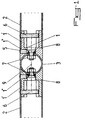
- Montagevorrichtung insbesondere für Hohlteile einer Brüstung, eines Geländers oder dergleichen, dadurch gekennzeichnet, daß sie im wesentlichen durch ein Montagestück (1) in dem Ende eines Pfostens oder einer Stange (2), eines Balkens oder einer Pfette, einer Unterpfette, eines Treppengeländers oder dergleichen ausgebildet ist, welches Montagestück (1) in dem Pfosten oder in der Stange (2) durch eine Einrichtung (3) zum Verbinden dieses Montagestücks (1) mit dem zuzuordnenden Ende eines zuzuordnenden Montagestücks (1) oder mit einem rohrförmigen Bauteil (4) befestigt ist, das den Pfosten oder dergleichen bildet, wobei das Montagestück (1) und die Verbindungseinrichtung (3) getrennt von dem Pfosten, der Stange (2), der Pfette, der Unterpfette, des Treppengeländers oder dergleichen oder an dem rohrförmigen Bauteil (4), das den Pfosten oder dergleichen bildet, montiert sind, und miteinander in der Art eines in einer Position blockierbaren Gelenks nach einer Einstellung mit Hilfe einer Montageeinrichtung (5) ohne Demontage vor dem Blockieren der montierten Bauteile an das Montagestück (1) und an die Verbindungseinrichtung (3) verbunden sind.
- Montagevorrichtung nach Anspruch 1, dadurch gekennzeichnet, daß das Montagestück (1) in dem Ende eines Pfostens oder einer Stange (2), eines Balkens oder einer Pfette, einer Unterpfette, eines Treppengeländers oder dergleichen in Form eines Bauteils mit einem Ende (1') gebildet ist, das in das entsprechende Ende des Pfostens oder der Stange (2) aufschrumpfbar ist, wobei ein Anschlag gegen das Ende der Pfostenstange mit Hilfe einer Schulter (1") gebildet ist, wobei der ortsfeste Sitz des Montagestücks (1) in dem Pfosten oder der Stange (2) durch eine Verbindungseinrichtung (6) sichergestellt ist, die die Wand des Pfostens oder der Stange (2) quert und in dem aufschrumpfbaren Ende (1') des Montagestücks (1) eingespannt ist.
- Montagevorrichtung nach Anspruch 2, dadurch gekennzeichnet, daß das aufschrumpfbare Ende (1') des Montagesstücks (1) diametral gegenüberliegende Teile umfaßt, von denen ein Teil von der Verbindungseinrichtung (6), die die Wand des Pfostens oder der Stange (2) durchquert, durchquert ist und von denen der anderen Teil eine Abstützfläche für das Ende der Verbindungseinrichtung (6) bildet.
- Montagevorrichtung nach einem der Ansprüche 1 und 2 oder 3, dadurch gekennzeichnet, daß die Verbindungseinrichtung (6) durch eine kopflose Schraube gebildet ist, die durch ein Loch eines entsprechenden Abschnitts der Wand des Pfostens oder der Stange (2) verläuft und mit einem Gewinde zusammenwirkt, das einem Teil des schrumpfbaren Endes (1') des Montagestücks (1) zugehörig ist, wobei die Länge dieser Schraube derart ist, daß sie vollständig bezüglich der Außenfläche des Pfostens oder der Stange (2) in der Betriebsposition versenkt ist.
- Montagevorrichtung nach Anspruch 1, dadurch gekennzeichnet, daß die Verbindungseinrichtung (3) des Montagestücks (1) mit dem zuzuordnenden Ende eines zuzuordnenden Montagestücks (1) durch ein kugelförmiges Teil gebildet ist, das mit wenigstens zwei Querbolzen (7) versehen ist, dessen Schraubenkopf vorteilhafterweise konisch ist, wobei jeder Schraubenkopf durch eine Bohrung (8) eines zuzuordnenden Abschnitts des zuzuordnenden Montagestücks (1) eindringt, wobei das zuzuordnende freie Ende des Montagestücks (1) eine konkave hemisphärische Form aufweist, die der der Einrichtung (3) entspricht.
- Montagevorrichtung nach den Ansprüchen 1 und 5, dadurch gekennzeichnet, daß wenigstens ein Durchgangsloch für Schrauben, die die Bolzen (7) bilden, ein Langloch (9) ist.
- Montagevorrichtung nach den Ansprüchen 1 und 5, dadurch gekennzeichnet, daß die Verbindungseinrichtung (3) des Stücks (1) mit dem zuzuordnenden Ende eines zuzuordnenden Montagestücks (1) als rohrförmiges Bauteil ausgebildet ist, das mit zwei Durchgangslöchern für die Schrauben versehen ist, welche die Bolzen (7) bilden, wobei ein Loch als Langloch ausgeführt ist, wobei die Löcher in einer Ebene oder in unterschiedlichen Ebenen liegen können, wobei das entsprechende freie Ende des Montagestücks (1) eine halbzylindrische, konkave Form aufweist, die der der Einrichtung (3) entspricht.
- Montagevorrichtung nach den Ansprüchen 1 und 5, dadurch gekennzeichnet, daß die Verbindungseinrichtung (3) eines Montagestücks (1) mit einem rohrförmigen Bauteil (4), das einen Pfosten oder dergleichen bildet, in Form eines Verbindungselements der weiblich-weiblichen Art ausgebildet ist, von dem ein Ende mit einer hemisphärischen Aussparung (10) versehen ist, die mit einem zuzuordnenden hemisphärischen Ende eines Montagestücks (1) zusammenwirken kann, und dessen anderes Ende eine halbzylindrische Vertiefung (11) aufweist, die ein Zusammenwirken mit dem zylindrischen Pfosten (4) oder dergleichen zuläßt, wobei die Achse der halbzylindrischen Vertiefung (11) vorteilhafterweise in einer Ebene liegt, welche die Ebene der hemisphärischen Aussparung (10) schneidet und von 90° unterschiedlich ist, wobei der Montagebolzen (7) an dem Ende des Montagestücks (1) montiert ist.
- Montagevorrichtung nach Anspruch 8, dadurch gekennzeichnet, daß das hemisphärische Ende des Montagestücks (1) mit einem Durchgangslangloch für die Schraube versehen ist, die den Bolzen (7) für die Montage mit der Verbindungseinrichtung (3) bildet, wobei die Befestigung des Bolzens an dem rohrförmigen Bauteil (4), das den Pfosten oder dergleichen bildet, mit Hilfe einer Schraube (12) oder dergleichen realisiert ist, die in dem Körper der Verbindungseinrichtung (3) sitzt und mit einem Zapfen oder dergleichen zusammenwirkt, der an dem Pfosten (4) vorgesehen ist.
- Montagevorrichtung nach den Ansprüchen 1 und 5 bis 9, dadurch gekennzeichnet, daß die Einrichtung (5) zur Montage und zur Positionsblockade nach dem Einstellen des Montagestücks (1) und der Verbindungseinrichtung (3) durch wenigstens eine Druckschraube mit einem konischen Ende gebildet ist, das sich an der konischen Fläche des Kopfes der Schraube abstützt, die den Montagebolzen (7) bildet.
- Montagevorrichtung nach den Ansprüchen 1 und 5 bis 10, dadurch gekennzeichnet, daß ein Abstand zwischen dem Kopf der den Montagebolzen (7) bildenden Schraube und dem kugelförmigen oder zylindrischen Umfang, an dem der Bolzen (7) montiert ist, durch Vorsehen eines Ringes (13) aus einem Elastomer oder einem anderen Material zwischen dem Kopf und dem kugelförmigen oder zylindrischen Umfang festgelegt ist.
- Montagevorrichtung nach Anspruch 1, dadurch gekennzeichnet, daß die verschiedenen Verbindungen der Bauart mit ebenen Flächen der Kooperation mit winkligen Formen entsprechen.
Applications Claiming Priority (2)
| Application Number | Priority Date | Filing Date | Title |
|---|---|---|---|
| FR9801803 | 1998-02-11 | ||
| FR9801803A FR2774714B1 (fr) | 1998-02-11 | 1998-02-11 | Dispositif d'assemblage, en particulier pour elements creux de garde-corps ou analogue |
Publications (3)
| Publication Number | Publication Date |
|---|---|
| EP0936360A2 EP0936360A2 (de) | 1999-08-18 |
| EP0936360A3 EP0936360A3 (de) | 2001-11-07 |
| EP0936360B1 true EP0936360B1 (de) | 2005-10-05 |
Family
ID=9522985
Family Applications (1)
| Application Number | Title | Priority Date | Filing Date |
|---|---|---|---|
| EP19990440025 Expired - Lifetime EP0936360B1 (de) | 1998-02-11 | 1999-02-05 | Zusammenbauvorrichtung, insbesondere für rohrförmige Elemente |
Country Status (4)
| Country | Link |
|---|---|
| EP (1) | EP0936360B1 (de) |
| DE (1) | DE69927538T2 (de) |
| ES (1) | ES2249876T3 (de) |
| FR (1) | FR2774714B1 (de) |
Families Citing this family (5)
| Publication number | Priority date | Publication date | Assignee | Title |
|---|---|---|---|---|
| DE20100893U1 (de) * | 2001-01-17 | 2001-06-28 | Cronenberg Ohg J | Einrichtung für die Befestigung einer Geländerstrebe an einem Pfosten |
| DE20203656U1 (de) * | 2002-03-06 | 2003-07-17 | Leitner Gmbh | Verbindungsanordnung |
| DE20313143U1 (de) * | 2003-08-22 | 2004-12-30 | Rixen, Wolfgang, Dipl.-Ing. | Verbindungselement |
| FR2963395B1 (fr) * | 2010-07-27 | 2014-02-21 | Proinoxasi | Ensemble d'elements emboitables destine notamment a former un garde-corps, une balustrade, une rampe ou un conduit de fluide |
| CN108569179B (zh) * | 2017-03-14 | 2021-05-14 | 湖南中车时代电动汽车股份有限公司 | 一种车载扶手杆连接配件及扶手杆装配方法 |
Family Cites Families (5)
| Publication number | Priority date | Publication date | Assignee | Title |
|---|---|---|---|---|
| US4150907A (en) * | 1978-03-08 | 1979-04-24 | Julius Blum & Co., Inc. | Stanchion connector assembly |
| GB2149047B (en) * | 1983-10-29 | 1988-04-13 | Brian Laurance Wright | Connecting arrangement |
| US4867596A (en) * | 1988-08-04 | 1989-09-19 | Morton Ocuin | Connector for elongate elements |
| DE4336282A1 (de) * | 1993-10-25 | 1995-04-27 | Kreusel Magda | Verbindungselement für zwei sich kreuzende Rohre |
| FR2713723B1 (fr) | 1993-12-10 | 1996-01-12 | Schutt Ferronniers Art Sa | Dispositif d'assemblage, en particulier pour éléments creux de garde-corps ou analogue. |
-
1998
- 1998-02-11 FR FR9801803A patent/FR2774714B1/fr not_active Expired - Fee Related
-
1999
- 1999-02-05 DE DE69927538T patent/DE69927538T2/de not_active Expired - Lifetime
- 1999-02-05 EP EP19990440025 patent/EP0936360B1/de not_active Expired - Lifetime
- 1999-02-05 ES ES99440025T patent/ES2249876T3/es not_active Expired - Lifetime
Also Published As
| Publication number | Publication date |
|---|---|
| DE69927538D1 (de) | 2006-02-16 |
| DE69927538T2 (de) | 2006-07-06 |
| EP0936360A3 (de) | 2001-11-07 |
| FR2774714A1 (fr) | 1999-08-13 |
| EP0936360A2 (de) | 1999-08-18 |
| FR2774714B1 (fr) | 2000-04-14 |
| ES2249876T3 (es) | 2006-04-01 |
Similar Documents
| Publication | Publication Date | Title |
|---|---|---|
| EP0964107A1 (de) | Verbindungsknoten | |
| CA2239933C (fr) | Dispositif de jonction pour main courante | |
| EP0936360B1 (de) | Zusammenbauvorrichtung, insbesondere für rohrförmige Elemente | |
| WO1993005749A1 (fr) | Dispositif d'aide a la marche, de type bequille ou canne anglaise | |
| FR2668800A2 (fr) | Dispositif de liaison pour reunir bout a bout deux barres. | |
| EP2003265B1 (de) | System für Geländer, Rampen oder für ähnliche Zwecke | |
| FR2868136A1 (fr) | Vis pour accrocher un profile creux en matiere plastique renforce par un profile metallique a une infrastructure | |
| US4643607A (en) | Furniture construction | |
| FR2713723A1 (fr) | Dispositif d'assemblage, en particulier pour éléments creux de garde-corps ou analogue. | |
| FR2915500A1 (fr) | Garde-corps. | |
| FR2978780A1 (fr) | Dispositif de raccordement d'elements tubulaires et systeme l'integrant | |
| EP1072738B1 (de) | Verbindungsschelle insbesondere für Strassenmöbel | |
| FR2690185A1 (fr) | Dispositif de fixation pour garde-corps. | |
| EP1544478B1 (de) | Zusammengesetzte Rohrschelle | |
| FR2951510A1 (fr) | Dispositif de raccordement d'elements tubulaires | |
| EP0462039A1 (de) | Modulartige Spielvorrichtung | |
| FR2519052A1 (fr) | Balustrade en elements prefabriques reglables pour la protection et la delimitation de surfaces planes et inclinees | |
| FR2711701A1 (fr) | Dispositif pour l'assemblage de barreaux avec une lisse de garde-corps. | |
| FR2819861A1 (fr) | Dispositif pour fixer en bout une barre sur un support | |
| FR2717196A1 (fr) | Dispositif d'assemblage perfectionné de glissières de sécurité routière en bois. | |
| FR2684145A1 (fr) | Douille tubulaire de cheville a noyau d'expansion. | |
| FR2586049A1 (fr) | Structure porteuse pour la realisation d'elements volumiques, notamment destines a etre accoles a des batiments | |
| EP1318251A1 (de) | Sicherheitsgelenk für Geländer von Gerüsten | |
| FR2852987A1 (fr) | Garde-corps | |
| FR2802958A1 (fr) | Etai presentant au moins un bras compose de deux elements telescopiques tubulaires et un ensemble de verrouillage independant |
Legal Events
| Date | Code | Title | Description |
|---|---|---|---|
| PUAI | Public reference made under article 153(3) epc to a published international application that has entered the european phase |
Free format text: ORIGINAL CODE: 0009012 |
|
| AK | Designated contracting states |
Kind code of ref document: A2 Designated state(s): AT BE CH CY DE DK ES FI FR GB GR IE IT LI LU MC NL PT SE Kind code of ref document: A2 Designated state(s): BE DE ES FR GB IT NL |
|
| AX | Request for extension of the european patent |
Free format text: AL;LT;LV;MK;RO;SI |
|
| PUAL | Search report despatched |
Free format text: ORIGINAL CODE: 0009013 |
|
| AK | Designated contracting states |
Kind code of ref document: A3 Designated state(s): AT BE CH CY DE DK ES FI FR GB GR IE IT LI LU MC NL PT SE |
|
| AX | Request for extension of the european patent |
Free format text: AL;LT;LV;MK;RO;SI |
|
| RIC1 | Information provided on ipc code assigned before grant |
Free format text: 7E 04F 11/18 A, 7F 16B 7/04 B |
|
| 17P | Request for examination filed |
Effective date: 20011221 |
|
| AKX | Designation fees paid |
Free format text: BE DE ES FR GB IT NL |
|
| 17Q | First examination report despatched |
Effective date: 20041227 |
|
| GRAP | Despatch of communication of intention to grant a patent |
Free format text: ORIGINAL CODE: EPIDOSNIGR1 |
|
| GRAS | Grant fee paid |
Free format text: ORIGINAL CODE: EPIDOSNIGR3 |
|
| GRAA | (expected) grant |
Free format text: ORIGINAL CODE: 0009210 |
|
| AK | Designated contracting states |
Kind code of ref document: B1 Designated state(s): BE DE ES FR GB IT NL |
|
| REG | Reference to a national code |
Ref country code: GB Ref legal event code: FG4D Free format text: NOT ENGLISH |
|
| GBT | Gb: translation of ep patent filed (gb section 77(6)(a)/1977) | ||
| REF | Corresponds to: |
Ref document number: 69927538 Country of ref document: DE Date of ref document: 20060216 Kind code of ref document: P |
|
| PGFP | Annual fee paid to national office [announced via postgrant information from national office to epo] |
Ref country code: IT Payment date: 20060228 Year of fee payment: 8 |
|
| REG | Reference to a national code |
Ref country code: ES Ref legal event code: FG2A Ref document number: 2249876 Country of ref document: ES Kind code of ref document: T3 |
|
| PLBE | No opposition filed within time limit |
Free format text: ORIGINAL CODE: 0009261 |
|
| STAA | Information on the status of an ep patent application or granted ep patent |
Free format text: STATUS: NO OPPOSITION FILED WITHIN TIME LIMIT |
|
| 26N | No opposition filed |
Effective date: 20060706 |
|
| PG25 | Lapsed in a contracting state [announced via postgrant information from national office to epo] |
Ref country code: IT Free format text: LAPSE BECAUSE OF NON-PAYMENT OF DUE FEES Effective date: 20070205 |
|
| PGFP | Annual fee paid to national office [announced via postgrant information from national office to epo] |
Ref country code: ES Payment date: 20091230 Year of fee payment: 12 |
|
| PGFP | Annual fee paid to national office [announced via postgrant information from national office to epo] |
Ref country code: FR Payment date: 20100112 Year of fee payment: 12 |
|
| PGFP | Annual fee paid to national office [announced via postgrant information from national office to epo] |
Ref country code: GB Payment date: 20100224 Year of fee payment: 12 Ref country code: DE Payment date: 20100302 Year of fee payment: 12 Ref country code: BE Payment date: 20100129 Year of fee payment: 12 |
|
| PGFP | Annual fee paid to national office [announced via postgrant information from national office to epo] |
Ref country code: NL Payment date: 20100215 Year of fee payment: 12 |
|
| BERE | Be: lapsed |
Owner name: S.A. *GRANDE FORGE MANAGEMENT Effective date: 20110228 |
|
| REG | Reference to a national code |
Ref country code: NL Ref legal event code: V1 Effective date: 20110901 |
|
| GBPC | Gb: european patent ceased through non-payment of renewal fee |
Effective date: 20110205 |
|
| REG | Reference to a national code |
Ref country code: FR Ref legal event code: ST Effective date: 20111102 |
|
| PG25 | Lapsed in a contracting state [announced via postgrant information from national office to epo] |
Ref country code: BE Free format text: LAPSE BECAUSE OF NON-PAYMENT OF DUE FEES Effective date: 20110228 |
|
| PG25 | Lapsed in a contracting state [announced via postgrant information from national office to epo] |
Ref country code: NL Free format text: LAPSE BECAUSE OF NON-PAYMENT OF DUE FEES Effective date: 20110901 |
|
| REG | Reference to a national code |
Ref country code: DE Ref legal event code: R119 Ref document number: 69927538 Country of ref document: DE Effective date: 20110901 |
|
| PG25 | Lapsed in a contracting state [announced via postgrant information from national office to epo] |
Ref country code: FR Free format text: LAPSE BECAUSE OF NON-PAYMENT OF DUE FEES Effective date: 20110228 |
|
| PG25 | Lapsed in a contracting state [announced via postgrant information from national office to epo] |
Ref country code: GB Free format text: LAPSE BECAUSE OF NON-PAYMENT OF DUE FEES Effective date: 20110205 |
|
| REG | Reference to a national code |
Ref country code: ES Ref legal event code: FD2A Effective date: 20120411 |
|
| PG25 | Lapsed in a contracting state [announced via postgrant information from national office to epo] |
Ref country code: ES Free format text: LAPSE BECAUSE OF NON-PAYMENT OF DUE FEES Effective date: 20110206 |
|
| PG25 | Lapsed in a contracting state [announced via postgrant information from national office to epo] |
Ref country code: DE Free format text: LAPSE BECAUSE OF NON-PAYMENT OF DUE FEES Effective date: 20110901 |