EP0936360B1 - Assembling device, in particular for tubular elements - Google Patents
Assembling device, in particular for tubular elements Download PDFInfo
- Publication number
- EP0936360B1 EP0936360B1 EP19990440025 EP99440025A EP0936360B1 EP 0936360 B1 EP0936360 B1 EP 0936360B1 EP 19990440025 EP19990440025 EP 19990440025 EP 99440025 A EP99440025 A EP 99440025A EP 0936360 B1 EP0936360 B1 EP 0936360B1
- Authority
- EP
- European Patent Office
- Prior art keywords
- mounting part
- post
- bar
- assembly
- assembly device
- Prior art date
- Legal status (The legal status is an assumption and is not a legal conclusion. Google has not performed a legal analysis and makes no representation as to the accuracy of the status listed.)
- Expired - Lifetime
Links
- 229920001971 elastomer Polymers 0.000 claims description 2
- 239000000806 elastomer Substances 0.000 claims description 2
- 230000000149 penetrating effect Effects 0.000 claims description 2
- 238000007373 indentation Methods 0.000 claims 2
- 230000001747 exhibiting effect Effects 0.000 claims 1
- 239000000470 constituent Substances 0.000 description 2
- 238000004519 manufacturing process Methods 0.000 description 2
- 230000000712 assembly Effects 0.000 description 1
- 238000000429 assembly Methods 0.000 description 1
- 230000000903 blocking effect Effects 0.000 description 1
- 230000004048 modification Effects 0.000 description 1
- 238000012986 modification Methods 0.000 description 1
- 230000003071 parasitic effect Effects 0.000 description 1
- 238000010079 rubber tapping Methods 0.000 description 1
- 238000000926 separation method Methods 0.000 description 1
- 238000006467 substitution reaction Methods 0.000 description 1
Images

Classifications
-
- E—FIXED CONSTRUCTIONS
- E04—BUILDING
- E04F—FINISHING WORK ON BUILDINGS, e.g. STAIRS, FLOORS
- E04F11/00—Stairways, ramps, or like structures; Balustrades; Handrails
- E04F11/18—Balustrades; Handrails
- E04F11/181—Balustrades
- E04F11/1817—Connections therefor
-
- F—MECHANICAL ENGINEERING; LIGHTING; HEATING; WEAPONS; BLASTING
- F16—ENGINEERING ELEMENTS AND UNITS; GENERAL MEASURES FOR PRODUCING AND MAINTAINING EFFECTIVE FUNCTIONING OF MACHINES OR INSTALLATIONS; THERMAL INSULATION IN GENERAL
- F16B—DEVICES FOR FASTENING OR SECURING CONSTRUCTIONAL ELEMENTS OR MACHINE PARTS TOGETHER, e.g. NAILS, BOLTS, CIRCLIPS, CLAMPS, CLIPS OR WEDGES; JOINTS OR JOINTING
- F16B7/00—Connections of rods or tubes, e.g. of non-circular section, mutually, including resilient connections
- F16B7/04—Clamping or clipping connections
- F16B7/044—Clamping or clipping connections for rods or tubes being in angled relationship
- F16B7/0446—Clamping or clipping connections for rods or tubes being in angled relationship for tubes using the innerside thereof
- F16B7/0453—Clamping or clipping connections for rods or tubes being in angled relationship for tubes using the innerside thereof the tubes being drawn towards each other
Definitions
- the present invention relates to the field of manufacture industrial manufacture of ironwork, in particular for railings, railings and analogous, and relates to an assembly device, in particular for elements guard rail trough or the like.
- connection means are generally in the form of rigid tee connections, in the case of mounting smooth or under-slats, or in the form of a set of parts hinged together means of a locking pin in the service position, one of the parts being inserted in the end of the pole or bar and forming the pivot of the other piece of receiving and supporting the constituent tube of the stair rail or the like, the fixing the pivot piece in the corresponding end of the bar or pole and the fixing of the tube forming a stair rail or the like being made by means of countersunk screws.
- the devices existing ones are of a relatively high cost price.
- the aesthetic appearance of the devices obtained is relatively questionable, the hinge element necessarily forming a harmful interruption from this point of view.
- the very presence of a articulation requires a suitable tightening after setting up the different elements, to avoid any parasitic play.
- a device assembly for hollow railing elements or the like which is essentially constituted by a mounting piece in the end of a pole or a bar fixed in said post or bar and by a support piece provided with a cradle for receiving a tubular element forming a smooth, sub-smooth, ramp or the like, the two parts being interconnected by means of a ball joint which can be locked in position, after adjustment, by via at least one connecting means.
- This embodiment allows obtaining an assembly that can be entirely prefabricated and favoring a quick assembly with relatively low tooling costs.
- this assembly device requires, for final tightening of the mounting piece on the support piece, a disassembly of the ramp or smooth after adjusting the position of the latter, in order to access the assembly means.
- document GB-A-2 149 047 describes a device of assembly between two elements of cylindrical section implementing a Stud tightened in a blind hole by means of a set screw. This document only describes perfectly predetermined assemblies not allowing no angular adjustment of the alignment type of two pieces in extension or two-piece mounting with the possibility of adjustable angular offset.
- this document does not disclose any device of assembly allowing a position adjustment of the parts to be assembled before their permanent locking in position, without requiring disassembly before blocking the set position, then a reassembly of the elements to be mounted between them.
- the present invention aims to overcome the disadvantages of assembly devices known to date by proposing an assembly device, in particular for hollow elements of guardrails or the like, allowing perform quick and easy assembly, adjustment and locking of its parts constituent.
- the device according to the invention is characterized in that that it basically consists of a mounting piece in the end of a post or bar, a rail, a sub-rail, a rail or the like, fixed in said post or bar, and by a connecting means of this piece of mounting with the corresponding end of a corresponding mounting piece or with a tubular element forming a smooth, sub-smooth, ramp or post or analogous, said mounting piece and the connecting means being connected to one another way of a hinge that can be locked in position, after adjustment, by via at least one connecting means.
- the assembly device in particular for hollow guardrail elements or analogous, essentially consists of a mounting piece 1 in the end of a pole or of a bar 2, a rail, a sub-rail, a rail ramp or the like, fixed in said post or bar 2 and by means 3 of connection of this mounting piece 1 with the corresponding end of a piece of corresponding assembly 1 (FIG. 1) or with a tubular element 4 forming post or the like (FIG. 2), said mounting piece 1 and the connecting means 3 being interconnected in the manner of a hinge that can be locked into position, after adjustment, via at least one connecting means 5.
- the mounting piece 1 in the end of a post or bar 2 of a rail, a sub-rail, a ramp or the like is advantageously constituted in the form of an element presenting an end 1 'snag in the corresponding end of said pole or bar 2 with abutment against said end of the latter by via a shoulder 1 ", the holding of said mounting piece 1 in the post or bar 2 being provided by a connecting means 6 passing through the wall of the post or bar 2 and tight in the end emmanchable 1 'of the room of Mounting 1.
- the emmanchable end 1 'of the mounting piece 1 has two diametrically opposite parts, one of which is crossed by the medium bond 6 passing through the wall of the post or bar 2 and the other form a bearing surface for the end of said connecting means 6.
- the latter is preferably constituted by a grub screw through a hole of corresponding section of the wall of the post or bar 2 and cooperating with a corresponding tapping of a part of the end 1 'of the mounting part 1, the length of this screw being such that it is completely drowned on the external surface of the post or bar 2 in service position.
- the means 3 for connecting the mounting piece 1 with the end corresponding part of a corresponding mounting part 1 ( Figure 1) is advantageously constituted, according to a first embodiment of the invention, by a spherical element provided with at least two through bolts 7, whose head screw is advantageously conical, each screw head penetrating into a bore 8 of corresponding section of the corresponding mounting piece 1, the end corresponding free movement of the mounting piece 1 having a concave shape hemisphere corresponding to that of the means 3.
- at least one of the through holes of the screws forming the bolts 7 is an oblong hole 9.
- the means 3 of connecting the workpiece 1 with the end corresponding part of a corresponding mounting part 1 in the form of an element tubular having at least two through-holes for bolts forming bolts 7, one of these holes being advantageously oblong, these holes being able to be in a same plane or in different planes, the corresponding free end of the mounting piece 1 having a corresponding semi-cylindrical concave shape to that of the means 3.
- Such an embodiment allows the implementation of tubular elements forming bars receiving posts, smooth or analogous, said bars, smooth or the like, connectable to said poles at different levels, for example for a level change from one litter to another.
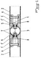
- Figure 2 of the accompanying drawings represents another variant of embodiment of the invention, in which the means 3 for connecting a piece of assembly 1 with a tubular element 4 forming a pole or the like is presented in the form of a female-female connecting element, one of whose ends is provided with a hemispherical recess 10 which can cooperate with one end corresponding hemispherical part of a mounting piece 1 and whose other end is provided with a semi-cylindrical imprint 11 for cooperation with a cylindrical post 4 or the like, the axis of the semi-cylindrical imprint 11 being advantageously located in a plane secant from that of the recess hemispherical 10, different from 90 ° and the bolt 7 assembly being mounted on the end of the mounting piece 1.
- the end hemispherical part of the mounting part 1 is advantageously provided with a hole oblong passage of the screw forming the bolt 7 assembly with the means of connection 3, the attachment of the latter on the tubular element 4 forming a pole or analogous being achieved by means of a screw 12 or the like housed in the body of the connecting means 3 and cooperating with an anchor or the like provided in the post 4.
- the means 5 for assembling and locking in position, after adjustment, of the mounting part 1 and the connecting means 3 is advantageously constituted by at least one conical end pressure screw, said end of which bears under the face tapered head of the screw forming the bolt 7 assembly.
- a gap between the screw head forming the bolt 7 assembly and the spherical or cylindrical bearing on which is mounted said bolt 7 is provided by providing a ring 13 of elastomer or the like between said head and said span spherical or cylindrical.
- the invention it is possible to produce an assembly, particular of decorative hollow elements, in the field of ironwork, particularly used for obtaining railings, balustrades or others, whose individual components can be mounted separately on the respective tubes, while being able to be positioned easily.
Description
La présente invention concerne le domaine de la fabrication industrielle de pièces de ferronnerie, notamment pour garde-corps, balustrades et analogues, et a pour objet un dispositif d'assemblage, en particulier pour éléments creux de garde-corps ou analogue.The present invention relates to the field of manufacture industrial manufacture of ironwork, in particular for railings, railings and analogous, and relates to an assembly device, in particular for elements guard rail trough or the like.
Les lisses, sous-lisses, barreaux et poteaux constitutifs de garde-corps et de balustrades et analogues sont généralement assemblés entre eux par des moyens de raccordement pourvus, d'une part, d'un embout de montage dans une extrémité d'un tube formant barreau ou poteau et, d'autre part, d'une partie de support et de réception d'un tube formant lisse haute ou basse ou rampe d'escalier.Smooth, sub-smooth, bars and posts constituting guardrails and balustrades and the like are usually assembled together by connecting means provided, on the one hand, with a mounting bit in one end of a tube forming a bar or pole and, on the other hand, of a part of support and reception of a tube forming smooth high or low or stair railing.
Ces moyens de raccordement connus se présentent généralement sous forme de raccords en té rigides, dans le cas de montage de lisses ou sous-lisses, ou encore sous forme d'un ensemble de pièces articulées entre-elles au moyen d'un axe de blocage en position de service l'une des pièces étant insérée dans l'extrémité du poteau ou du barreau et formant le pivot de l'autre pièce de réception et de support du tube constitutif de la rampe d'escalier ou analogue, la fixation de la pièce formant pivot dans l'extrémité correspondante du barreau ou poteau, ainsi que la fixation du tube formant rampe d'escalier ou analogue étant réalisées par l'intermédiaire de vis à tête noyée.These known connection means are generally in the form of rigid tee connections, in the case of mounting smooth or under-slats, or in the form of a set of parts hinged together means of a locking pin in the service position, one of the parts being inserted in the end of the pole or bar and forming the pivot of the other piece of receiving and supporting the constituent tube of the stair rail or the like, the fixing the pivot piece in the corresponding end of the bar or pole and the fixing of the tube forming a stair rail or the like being made by means of countersunk screws.
Ces moyens connus sont pourvus, en outre, dans la pièce formant pivot, d'un écrou rapporté d'assemblage et de serrage du poteau ou du barreau et permettent d'assurer un assemblage correct du poteau ou barreau, ainsi qu'un montage relativement efficace des lisses, sous-lisses, rampes ou analogues.These known means are further provided in the piece forming pivot, nut assembly and tightening the post or the bar and ensure correct assembly of the post or bar, as well as relatively effective mounting of the smooth, sub-smooth, ramps or the like.
Cependant, du fait de la nécessité de rapporter un écrou dans la partie mâle coopérant avec les extrémités des barreaux ou poteaux, les dispositifs existants sont d'un prix de revient relativement élevé. En outre, dans le cas de dispositifs en deux pièces articulées, l'aspect esthétique des dispositifs obtenus est relativement discutable, l'élément d'articulation formant forcément une interruption néfaste de ce point de vue. De plus, la présence même d'une articulation nécessite un serrage adapté après mise en place des différents éléments, afin d'éviter tout jeu parasite.However, because of the need to report a nut in the game male cooperating with the ends of the bars or posts, the devices existing ones are of a relatively high cost price. In addition, in the case of articulated two-piece devices, the aesthetic appearance of the devices obtained is relatively questionable, the hinge element necessarily forming a harmful interruption from this point of view. Moreover, the very presence of a articulation requires a suitable tightening after setting up the different elements, to avoid any parasitic play.
On connaít également, par FR-A-2 713 723 un dispositif d'assemblage pour éléments creux de garde-corps ou analogue, qui est essentiellement constitué par une pièce de montage dans l'extrémité d'un poteau ou d'un barreau fixée dans ledit poteau ou barreau et par une pièce de support pourvue d'un berceau de réception d'un élément tubulaire formant lisse, sous-lisse, rampe ou analogue, les deux pièces étant reliées entre elles au moyen d'une articulation à rotule pouvant être bloquée en position, après réglage, par l'intermédiaire d'au moins un moyen d'assemblage. Ce mode de réalisation permet l'obtention d'un assemblage pouvant être entièrement préfabriqué et favorisant un montage rapide avec des frais d'outillage relativement réduits.Also known from FR-A-2 713 723 is a device assembly for hollow railing elements or the like, which is essentially constituted by a mounting piece in the end of a pole or a bar fixed in said post or bar and by a support piece provided with a cradle for receiving a tubular element forming a smooth, sub-smooth, ramp or the like, the two parts being interconnected by means of a ball joint which can be locked in position, after adjustment, by via at least one connecting means. This embodiment allows obtaining an assembly that can be entirely prefabricated and favoring a quick assembly with relatively low tooling costs.
Cependant, ce dispositif d'assemblage nécessite, pour le serrage final de la pièce de montage sur la pièce de support, un démontage de la rampe ou lisse après réglage de position de cette dernière, afin d'accéder au moyen d'assemblage.However, this assembly device requires, for final tightening of the mounting piece on the support piece, a disassembly of the ramp or smooth after adjusting the position of the latter, in order to access the assembly means.
Par ailleurs, le document GB-A-2 149 047 décrit un dispositif d'assemblage entre deux éléments de section cylindrique mettant en oeuvre un goujon serré dans un perçage borgne au moyen d'une vis de pression. Ce document ne décrit que des assemblages parfaitement prédéterminés ne permettant aucun réglage angulaire du type alignement de deux pièces en prolongement ou montage de deux pièces avec possibilité de décalage angulaire réglable.Furthermore, document GB-A-2 149 047 describes a device of assembly between two elements of cylindrical section implementing a Stud tightened in a blind hole by means of a set screw. This document only describes perfectly predetermined assemblies not allowing no angular adjustment of the alignment type of two pieces in extension or two-piece mounting with the possibility of adjustable angular offset.
En outre, ce document ne divulgue nullement un dispositif d'assemblage permettant un réglage de position des pièces à assembler avant leur blocage définitif en position, ce sans nécessiter un démontage avant blocage de la position réglée, puis un remontage des éléments à monter entre eux.Furthermore, this document does not disclose any device of assembly allowing a position adjustment of the parts to be assembled before their permanent locking in position, without requiring disassembly before blocking the set position, then a reassembly of the elements to be mounted between them.
La présente invention a pour but de pallier les inconvénients des dispositifs d'assemblage connus à ce jour en proposant un dispositif d'assemblage, en particulier pour éléments creux de garde-corps ou analogue, permettant de réaliser un montage, un réglage et un blocage rapides et aisés de ses parties constitutives.The present invention aims to overcome the disadvantages of assembly devices known to date by proposing an assembly device, in particular for hollow elements of guardrails or the like, allowing perform quick and easy assembly, adjustment and locking of its parts constituent.
A cet effet, le dispositif conforme à l'invention est caractérisé en ce qu'il est essentiellement constitué par une pièce de montage dans l'extrémité d'un poteau ou d'un barreau, d'une lisse, d'une sous-lisse, d'une rampe ou analogue, fixée dans ledit poteau ou barreau, et par un moyen de liaison de cette pièce de montage avec l'extrémité correspondante d'une pièce de montage correspondante ou avec un élément tubulaire formant lisse, sous-lisse, rampe ou poteau ou analogue, ladite pièce de montage et le moyen de liaison étant reliés entre-eux à la manière d'une articulation pouvant être bloquée en position, après réglage, par l'intermédiaire d'au moins un moyen d'assemblage.For this purpose, the device according to the invention is characterized in that that it basically consists of a mounting piece in the end of a post or bar, a rail, a sub-rail, a rail or the like, fixed in said post or bar, and by a connecting means of this piece of mounting with the corresponding end of a corresponding mounting piece or with a tubular element forming a smooth, sub-smooth, ramp or post or analogous, said mounting piece and the connecting means being connected to one another way of a hinge that can be locked in position, after adjustment, by via at least one connecting means.
L'invention sera mieux comprise, grâce à la description ci-après, qui
se rapporte à des modes de réalisation préférés, donnés à titre d'exemples non
limitatifs, et expliqués avec référence aux dessins schématiques annexés, dans
lesquels :
Conformément à l'invention, et comme le montrent plus
particulièrement, à titre d'exemples, les figures 1 et 2 des dessins annexés, le
dispositif d'assemblage, en particulier pour éléments creux de garde-corps ou
analogue, est essentiellement constitué par une pièce 1 de montage dans
l'extrémité d'un poteau ou d'un barreau 2, d'une lisse, d'une sous-lisse, d'une
rampe ou analogue, fixée dans ledit poteau ou barreau 2 et par un moyen 3 de
liaison de cette pièce de montage 1 avec l'extrémité correspondante d'une pièce de
montage 1 correspondante (figure 1) ou avec un élément tubulaire 4 formant
poteau ou analogue (figure 2), ladite pièce de montage 1 et le moyen de liaison 3
étant reliés entre-eux à la manière d'une articulation pouvant être bloquée en
position, après réglage, par l'intermédiaire d'au moins un moyen d'assemblage 5.According to the invention, and as show more
particularly, by way of example, FIGS. 1 and 2 of the accompanying drawings, the
assembly device, in particular for hollow guardrail elements or
analogous, essentially consists of a
Selon une caractéristique de l'invention, la pièce 1 de montage dans
l'extrémité d'un poteau ou d'un barreau 2 d'une lisse, d'une sous-lisse, d'une rampe
ou analogue, est avantageusement constituée sous forme d'un élément présentant
une extrémité 1' emmanchable dans l'extrémité correspondante dudit poteau ou
barreau 2 avec mise en butée contre ladite extrémité de ce dernier par
l'intermédiaire d'un épaulement 1", le maintien de ladite pièce de montage 1 dans
le poteau ou barreau 2 étant assuré par un moyen de liaison 6 traversant la paroi du
poteau ou barreau 2 et serré dans l'extrémité emmanchable 1' de la pièce de
montage 1. De préférence, l'extrémité emmanchable 1' de la pièce de montage 1
présente deux parties diamétralement opposées, dont l'une est traversée par le
moyen liaison 6 traversant la paroi du poteau ou barreau 2 et dont l'autre forme
une surface d'appui pour l'extrémité dudit moyen liaison 6.According to a feature of the invention, the
Ce dernier est préférentiellement constitué par une vis sans tête
traversant un trou de section correspondante de la paroi du poteau ou barreau 2 et
coopérant avec un taraudage correspondant d'une partie de l'extrémité
emmanchable 1' de la pièce de montage 1, la longueur de cette vis étant telle
qu'elle soit complètement noyée à la surface externe du poteau ou barreau 2 en
position de service. Ainsi, il est possible de fixer la pièce de montage 1 dans
l'extrémité correspondante du poteau ou barreau 2 en assurant une esthétique
parfaite, le moyen de liaison 6 restant totalement invisible.The latter is preferably constituted by a grub screw
through a hole of corresponding section of the wall of the post or
Le moyen 3 de liaison de la pièce de montage 1 avec l'extrémité
correspondante d'une pièce de montage 1 correspondante (figure 1) est
avantageusement constitué, selon un premier mode de réalisation de l'invention,
par un élément sphérique muni d'au moins deux boulons traversants 7, dont la tête
de vis est avantageusement conique, chaque tête de vis pénétrant dans un perçage
8 de section correspondante de la pièce de montage 1 correspondante, l'extrémité
libre correspondante de la pièce de montage 1 présentant une forme concave
hémisphérique correspondant à celle du moyen 3. De préférence, au moins l'un des
trous de traversée des vis formant les boulons 7 est un trou oblong 9. Ainsi, il est
possible de réaliser une jonction bout à bout de deux barreaux 2 ou analogues,
éventuellement avec un changement de direction entre les deux barreaux 2.The
Conformément à une variante de réalisation de l'invention, il est
également possible de réaliser le moyen 3 de liaison de la pièce 1 avec l'extrémité
correspondante d'une pièce de montage 1 correspondante sous forme d'un élément
tubulaire muni d'au moins deux trous de passage pour les vis formant les boulons
7, l'un de ces trous étant avantageusement oblong, ces trous pouvant être dans un
même plan ou dans des plans différents, l'extrémité libre correspondante de la
pièce de montage 1 présentant une forme concave semi-cylindrique correspondant
à celle du moyen 3. Un tel mode de réalisation permet la mise en oeuvre
d'éléments tubulaires formant poteaux de réception de barreaux, lisses ou
analogues, lesdits barreaux, lisses ou analogues pouvant être reliés auxdits
poteaux à des niveaux différents, par exemple en vue d'un changement de niveau
du sol d'une portée à une autre.According to an alternative embodiment of the invention, it is
also possible to achieve the
La figure 2 des dessins annexés représente une autre variante de
réalisation de l'invention, dans laquelle le moyen 3 de liaison d'une pièce de
montage 1 avec un élément tubulaire 4 formant poteau ou analogue se présente
sous forme d'un élément de liaison femelle-femelle, dont l'une des extrémités est
munie d'un évidement hémisphérique 10 pouvant coopérer avec une extrémité
hémisphérique correspondante d'une pièce de montage 1 et dont l'autre extrémité
est pourvue d'une empreinte semi-cylindrique 11 permettant la coopération avec
un poteau cylindrique 4 ou analogue, l'axe de l'empreinte semi-cylindrique 11
étant avantageusement situé dans un plan sécant de celui de l'évidement
hémisphérique 10, différent de 90° et le boulon 7 d'assemblage étant monté sur
l'extrémité de la pièce de montage 1. Dans un tel mode de réalisation, l'extrémité
hémisphérique de la pièce de montage 1 est avantageusement muni d'un trou
oblong de passage de la vis formant le boulon 7 d'assemblage avec le moyen de
liaison 3, la fixation de ce dernier sur l'élément tubulaire 4 formant poteau ou
analogue étant réalisée par l'intermédiaire d'une vis 12 ou analogue, logée dans le
corps du moyen de liaison 3 et coopérant avec une cheville ou analogue prévue
dans le poteau 4. Ainsi, il est possible de réaliser une liaison entre un élément
formant poteau vertical 4 et un élément 2 s'étendant en oblique, par exemple de
garde-corps d'escalier, l'élément oblique 2 étant lui-même susceptible d'être
orienté du fait de la prévision d'un trou oblong de passage de la vis formant le
boulon 7.Figure 2 of the accompanying drawings represents another variant of
embodiment of the invention, in which the
Le moyen 5 d'assemblage et de blocage en position, après réglage, de
la pièce de montage 1 et du moyen de liaison 3, est avantageusement constitué par
au moins une vis de pression à bout conique, dont ledit bout s'appuie sous la face
conique de la tête de la vis formant le boulon 7 d'assemblage. Pour favoriser le
montage, un écartement entre la tête de vis formant le boulon 7 d'assemblage et la
portée sphérique ou cylindrique sur laquelle est monté ledit boulon 7 est assuré par
prévision d'un anneau 13 en élastomère ou autre entre ladite tête et ladite portée
sphérique ou cylindrique. Ainsi, il est toujours assuré un écartement suffisant entre
la portée sphérique ou cylindrique et la tête de vis pour permettre un montage et
un blocage aisés de la ou des vis de pression à bout conique constituant le moyen
5 d'assemblage. Dans le cas du montage selon la figure 2, l'accès au logement de
la vis 12 de fixation est réalisé par passage dans le trou de réception de la tête de
la vis formant le boulon 7.The
Dans la description ci-dessus, les différentes liaisons étaient du type à surfaces courbes, cependant, une liaison à surfaces planes, par coopération de formes angulaires, est également envisageable avec le dispositif selon l'invention.In the description above, the different links were of the type curved surfaces, however, a flat surface connection, by cooperation of angular forms, is also possible with the device according to the invention.
Grâce à l'invention il est possible de réaliser un assemblage, en particulier d'éléments creux décoratifs, dans le domaine de la ferronnerie, notamment mis en oeuvre pour l'obtention de garde-corps, de balustrades ou autres, dont les différents composants peuvent être montés séparément sur les tubes respectifs, tout en pouvant être positionnés aisément.Thanks to the invention it is possible to produce an assembly, particular of decorative hollow elements, in the field of ironwork, particularly used for obtaining railings, balustrades or others, whose individual components can be mounted separately on the respective tubes, while being able to be positioned easily.
Bien entendu, l'invention n'est pas limitée aux modes de réalisation décrits et représentés aux dessins annexés. Des modifications restent possibles, notamment du point de vue de la constitution des divers éléments ou par substitution d'équivalents techniques, sans sortir pour autant du domaine de protection de l'invention, qui est déterminé par la teneur des revendications.Of course, the invention is not limited to the embodiments described and shown in the accompanying drawings. Modifications are possible, particular from the point of view of the constitution of the various elements or by substitution of technical equivalents, without departing from the domain of protection of the invention, which is determined by the content of the claims.
Claims (12)
- Assembly device, in particular for hollow guard-rail elements or the like, characterised in that it substantially consists of a mounting part (1) in the end of a post or a bar (2), a rail, an under-rail, a ramp or the like, fixed in said post or bar (2), and of a means (3) for connecting this mounting part (1) to the corresponding end of a corresponding mounting part (1) or to a tubular element (4) forming the post or the like, the mounting part (1) and the connection means (3) being assembled separately on said post, bar (2), rail, under-rail, ramp or the like or on the tubular element (4) forming the post or the like, and being interconnected in the manner of a joint that is capable of being locked in position, after adjustment, by at least one assembly means (5), without disassembly, prior to locking, of the elements assembled on the mounting part (1) and on the connection means (3).
- Assembly device according to claim 1, characterised in that the mounting part (1) in the end of a post or a bar (2), a rail, an under-rail, a ramp or the like is in the form of an element having an end (1') that can be engaged in the corresponding end of said post or bar (2) while abutting against said end of said post or bar via a shoulder (1"), said mounting part (1) being held in the post or bar (2) by a connection means (6) passing through the wall of the post or bar (2) and gripped in the engageable end (1') of the mounting part (1).
- Assembly device according to claim 2, characterised in that the engageable end (1') of the mounting part (1) has two diametrically opposed portions, one of which is passed through by the connection means (6) passing through the wall of the post or bar (2) and the other of which forms a support surface for the end of said connection means (6).
- Assembly device according to any one of claims 1 and 2 or 3, characterised in that the connection means (6) consists of a headless screw passing through a hole of corresponding cross-section in the wall of the post or bar (2), and cooperating with a corresponding internal thread of a portion of the engageable end (1') of the mounting part (1), the length of this screw being such that it is completely embedded in the external surface of the post or bar (2) in the service position.
- Assembly device according to claim 1, characterised in that the means (3) for connecting the mounting part (1) to the corresponding end of a corresponding mounting part (1) consists of a spherical element provided with at least two through-bolts (7), the screw heads of which are advantageously conical, each screw head penetrating a perforation (8) of corresponding cross-section in the corresponding mounting part (1), the corresponding free end of the mounting part (1) having a hemispherical concave shape corresponding to that of the means (3).
- Assembly device according to claims 1 and 5, characterised in that at least one of the holes passed through by the screws forming the bolts (7) is an oblong hole (9).
- Assembly device according to claims 1 and 5, characterised in that the means (3) for connecting the part (1) to the corresponding end of a corresponding mounting part (1) is in the form of a tubular element provided with at least two passage holes for the screws forming the bolts (7), one of these holes being oblong, wherein these holes may be in the same plane or in different planes, the corresponding free end of the mounting part (1) having a semi-cylindrical concave shape corresponding to that of the means (3).
- Assembly device according to claims 1 and 5, characterised in that the means (3) for connecting a mounting part (1) to a tubular element (4) forming the post or the like is in the form of a female/female connection element, one of the ends of which is provided with a hemispherical recess (10) capable of cooperating with a corresponding hemispherical end of a mounting part (1) and the other end of which is provided with a semi-cylindrical indentation (11) allowing cooperation with a cylindrical post (4) or the like, the axis of the semi-cylindrical indentation (11) advantageously being arranged in a plane intersecting that of the hemispherical recess (10), differing by 90°, and the assembly bolt (7) being mounted on the end of the mounting part (1).
- Assembly device according to claim 8, characterised in that the hemispherical end of the mounting part (1) is provided with an oblong hole for passage of the screw forming the bolt (7) for assembly on the connection means (3), said connection means being fixed onto the tubular element (4) forming the post or the like by a screw (12) or the like, accommodated in the body of the connection means (3) and cooperating with a dowel or the like provided in the post (4).
- Assembly device according to any one of claims 1 and 5 to 9, characterised in that the means (5) for assembly and locking in position of the mounting part (1) and the connection means (3), after adjustment, consists of at least one locking screw having a conical end, said end of which rests under the conical face of the head of the screw forming the assembly bolt (7).
- Assembly device according to any one of claims 1 and 5 to 10, characterised in that a gap between the screw head forming the assembly bolt (7) and the spherical or cylindrical support on which said bolt (7) is mounted is formed by the provision of a ring (13) made of elastomer or the like between said head and said spherical or cylindrical support.
- Assembly device according to claim 1, characterised in that the various connections are of the type exhibiting surfaces which are rendered planar by cooperation of angular shapes.
Applications Claiming Priority (2)
| Application Number | Priority Date | Filing Date | Title |
|---|---|---|---|
| FR9801803 | 1998-02-11 | ||
| FR9801803A FR2774714B1 (en) | 1998-02-11 | 1998-02-11 | ASSEMBLY DEVICE, PARTICULARLY FOR HOLLOW GUARDRAIL ELEMENTS OR THE LIKE |
Publications (3)
| Publication Number | Publication Date |
|---|---|
| EP0936360A2 EP0936360A2 (en) | 1999-08-18 |
| EP0936360A3 EP0936360A3 (en) | 2001-11-07 |
| EP0936360B1 true EP0936360B1 (en) | 2005-10-05 |
Family
ID=9522985
Family Applications (1)
| Application Number | Title | Priority Date | Filing Date |
|---|---|---|---|
| EP19990440025 Expired - Lifetime EP0936360B1 (en) | 1998-02-11 | 1999-02-05 | Assembling device, in particular for tubular elements |
Country Status (4)
| Country | Link |
|---|---|
| EP (1) | EP0936360B1 (en) |
| DE (1) | DE69927538T2 (en) |
| ES (1) | ES2249876T3 (en) |
| FR (1) | FR2774714B1 (en) |
Families Citing this family (5)
| Publication number | Priority date | Publication date | Assignee | Title |
|---|---|---|---|---|
| DE20100893U1 (en) * | 2001-01-17 | 2001-06-28 | Cronenberg Ohg J | Device for fastening a railing strut to a post |
| DE20203656U1 (en) * | 2002-03-06 | 2003-07-17 | Leitner Gmbh | Corner element to be used for joining box profiles, comprising insertion area for plug element to be attached to outer end of profile |
| DE20313143U1 (en) * | 2003-08-22 | 2004-12-30 | Rixen, Wolfgang, Dipl.-Ing. | connecting element |
| FR2963395B1 (en) * | 2010-07-27 | 2014-02-21 | Proinoxasi | ASSEMBLY OF EMBLEMABLE ELEMENTS INTENDED IN PARTICULAR TO FORM A GUARD RAIL, A BALUSTRADE, A RAMP OR A FLUID CONDUIT |
| CN108569179B (en) * | 2017-03-14 | 2021-05-14 | 湖南中车时代电动汽车股份有限公司 | Vehicle-mounted grab rail connecting accessory and grab rail assembling method |
Family Cites Families (5)
| Publication number | Priority date | Publication date | Assignee | Title |
|---|---|---|---|---|
| US4150907A (en) * | 1978-03-08 | 1979-04-24 | Julius Blum & Co., Inc. | Stanchion connector assembly |
| GB2149047B (en) * | 1983-10-29 | 1988-04-13 | Brian Laurance Wright | Connecting arrangement |
| US4867596A (en) * | 1988-08-04 | 1989-09-19 | Morton Ocuin | Connector for elongate elements |
| DE4336282A1 (en) * | 1993-10-25 | 1995-04-27 | Kreusel Magda | Connecting element for two intersecting tubes |
| FR2713723B1 (en) | 1993-12-10 | 1996-01-12 | Schutt Ferronniers Art Sa | Assembly device, in particular for hollow railing elements or the like. |
-
1998
- 1998-02-11 FR FR9801803A patent/FR2774714B1/en not_active Expired - Fee Related
-
1999
- 1999-02-05 ES ES99440025T patent/ES2249876T3/en not_active Expired - Lifetime
- 1999-02-05 EP EP19990440025 patent/EP0936360B1/en not_active Expired - Lifetime
- 1999-02-05 DE DE69927538T patent/DE69927538T2/en not_active Expired - Lifetime
Also Published As
| Publication number | Publication date |
|---|---|
| FR2774714A1 (en) | 1999-08-13 |
| DE69927538D1 (en) | 2006-02-16 |
| DE69927538T2 (en) | 2006-07-06 |
| EP0936360A3 (en) | 2001-11-07 |
| ES2249876T3 (en) | 2006-04-01 |
| FR2774714B1 (en) | 2000-04-14 |
| EP0936360A2 (en) | 1999-08-18 |
Similar Documents
| Publication | Publication Date | Title |
|---|---|---|
| EP0964107A1 (en) | Connector node | |
| CA2239933C (en) | Connecting device for a handrail | |
| EP0936360B1 (en) | Assembling device, in particular for tubular elements | |
| WO1993005749A1 (en) | Walking aid of the crutch or cane type | |
| FR2668800A2 (en) | Connection device for joining two bars end to end (for the butt-joining of two bars) | |
| EP2003265B1 (en) | System of balustrade, ramp or similar | |
| FR2868136A1 (en) | Screw for fastening window frames to walls has collar below its head, gap between two corresponding to thickness of outer profile wall and cylindrical section between collar and thread fitting through bores in inner profile walls | |
| US4643607A (en) | Furniture construction | |
| FR2713723A1 (en) | Assembly device, in particular for hollow guard rail elements or the like. | |
| EP0651110B1 (en) | Immobilization device of a vertical stiffener of railings opposing a floor support | |
| FR2915500A1 (en) | Balustrade for securing roofing, has longitudinal post with jaw that is mounted in sliding manner on post to displace jaw between remote and closer positions, and hooks defining housing that receives upper and lower sills in closer position | |
| FR2978780A1 (en) | Device for articulately connecting tube profiles as abutting portions of e.g. guard rails, has structural components including parts, where parts not connected by connections are fitted on or in tubular elements ends to be joined | |
| EP1072738B1 (en) | Assembly collar particularly for urban furniture | |
| FR2690185A1 (en) | Handrail fixing, e.g. for steps - comprises head which fits into upper end of supporting post and connects with recess in underside of handrail by rod and transverse bar | |
| FR2757891A1 (en) | Assembly system for forming veranda roofs | |
| EP1544478B1 (en) | Assembly of a pipe clamp | |
| FR2951510A1 (en) | Tubular elements i.e. rails, connecting device for use during construction of balustrade on roof of e.g. dwelling, has tubular segment including connection unit that connects free end of tubular segment to tubular element | |
| EP0462039A1 (en) | Modular toy device | |
| FR2519052A1 (en) | BALUSTRADE IN ADJUSTABLE PREFABRICATED ELEMENTS FOR PROTECTION AND DELIMITATION OF PLANED AND INCLINED SURFACES | |
| FR2819861A1 (en) | Fastening assembly for bar end to support e.g. for safety railing post comprises sole plate and shoe with adjustable fixings | |
| FR2717196A1 (en) | Wooden crash barrier for roads | |
| FR2684145A1 (en) | TUBULAR ANKLE BUSHING WITH EXPANSION CORE. | |
| FR2586049A1 (en) | CARRIER STRUCTURE FOR THE PRODUCTION OF VOLUMES, PARTICULARLY FOR ACCOMMODATION TO BUILDINGS | |
| EP1318251A1 (en) | Safety folding joint for railings of scaffolding | |
| FR2852987A1 (en) | Railing, has two posts, each constituting two wing shaped corners that are spaced apart and fix fillers e.g. top rail, in plane between posts |
Legal Events
| Date | Code | Title | Description |
|---|---|---|---|
| PUAI | Public reference made under article 153(3) epc to a published international application that has entered the european phase |
Free format text: ORIGINAL CODE: 0009012 |
|
| AK | Designated contracting states |
Kind code of ref document: A2 Designated state(s): AT BE CH CY DE DK ES FI FR GB GR IE IT LI LU MC NL PT SE Kind code of ref document: A2 Designated state(s): BE DE ES FR GB IT NL |
|
| AX | Request for extension of the european patent |
Free format text: AL;LT;LV;MK;RO;SI |
|
| PUAL | Search report despatched |
Free format text: ORIGINAL CODE: 0009013 |
|
| AK | Designated contracting states |
Kind code of ref document: A3 Designated state(s): AT BE CH CY DE DK ES FI FR GB GR IE IT LI LU MC NL PT SE |
|
| AX | Request for extension of the european patent |
Free format text: AL;LT;LV;MK;RO;SI |
|
| RIC1 | Information provided on ipc code assigned before grant |
Free format text: 7E 04F 11/18 A, 7F 16B 7/04 B |
|
| 17P | Request for examination filed |
Effective date: 20011221 |
|
| AKX | Designation fees paid |
Free format text: BE DE ES FR GB IT NL |
|
| 17Q | First examination report despatched |
Effective date: 20041227 |
|
| GRAP | Despatch of communication of intention to grant a patent |
Free format text: ORIGINAL CODE: EPIDOSNIGR1 |
|
| GRAS | Grant fee paid |
Free format text: ORIGINAL CODE: EPIDOSNIGR3 |
|
| GRAA | (expected) grant |
Free format text: ORIGINAL CODE: 0009210 |
|
| AK | Designated contracting states |
Kind code of ref document: B1 Designated state(s): BE DE ES FR GB IT NL |
|
| REG | Reference to a national code |
Ref country code: GB Ref legal event code: FG4D Free format text: NOT ENGLISH |
|
| GBT | Gb: translation of ep patent filed (gb section 77(6)(a)/1977) | ||
| REF | Corresponds to: |
Ref document number: 69927538 Country of ref document: DE Date of ref document: 20060216 Kind code of ref document: P |
|
| PGFP | Annual fee paid to national office [announced via postgrant information from national office to epo] |
Ref country code: IT Payment date: 20060228 Year of fee payment: 8 |
|
| REG | Reference to a national code |
Ref country code: ES Ref legal event code: FG2A Ref document number: 2249876 Country of ref document: ES Kind code of ref document: T3 |
|
| PLBE | No opposition filed within time limit |
Free format text: ORIGINAL CODE: 0009261 |
|
| STAA | Information on the status of an ep patent application or granted ep patent |
Free format text: STATUS: NO OPPOSITION FILED WITHIN TIME LIMIT |
|
| 26N | No opposition filed |
Effective date: 20060706 |
|
| PG25 | Lapsed in a contracting state [announced via postgrant information from national office to epo] |
Ref country code: IT Free format text: LAPSE BECAUSE OF NON-PAYMENT OF DUE FEES Effective date: 20070205 |
|
| PGFP | Annual fee paid to national office [announced via postgrant information from national office to epo] |
Ref country code: ES Payment date: 20091230 Year of fee payment: 12 |
|
| PGFP | Annual fee paid to national office [announced via postgrant information from national office to epo] |
Ref country code: FR Payment date: 20100112 Year of fee payment: 12 |
|
| PGFP | Annual fee paid to national office [announced via postgrant information from national office to epo] |
Ref country code: GB Payment date: 20100224 Year of fee payment: 12 Ref country code: DE Payment date: 20100302 Year of fee payment: 12 Ref country code: BE Payment date: 20100129 Year of fee payment: 12 |
|
| PGFP | Annual fee paid to national office [announced via postgrant information from national office to epo] |
Ref country code: NL Payment date: 20100215 Year of fee payment: 12 |
|
| BERE | Be: lapsed |
Owner name: S.A. *GRANDE FORGE MANAGEMENT Effective date: 20110228 |
|
| REG | Reference to a national code |
Ref country code: NL Ref legal event code: V1 Effective date: 20110901 |
|
| GBPC | Gb: european patent ceased through non-payment of renewal fee |
Effective date: 20110205 |
|
| REG | Reference to a national code |
Ref country code: FR Ref legal event code: ST Effective date: 20111102 |
|
| PG25 | Lapsed in a contracting state [announced via postgrant information from national office to epo] |
Ref country code: BE Free format text: LAPSE BECAUSE OF NON-PAYMENT OF DUE FEES Effective date: 20110228 |
|
| PG25 | Lapsed in a contracting state [announced via postgrant information from national office to epo] |
Ref country code: NL Free format text: LAPSE BECAUSE OF NON-PAYMENT OF DUE FEES Effective date: 20110901 |
|
| REG | Reference to a national code |
Ref country code: DE Ref legal event code: R119 Ref document number: 69927538 Country of ref document: DE Effective date: 20110901 |
|
| PG25 | Lapsed in a contracting state [announced via postgrant information from national office to epo] |
Ref country code: FR Free format text: LAPSE BECAUSE OF NON-PAYMENT OF DUE FEES Effective date: 20110228 |
|
| PG25 | Lapsed in a contracting state [announced via postgrant information from national office to epo] |
Ref country code: GB Free format text: LAPSE BECAUSE OF NON-PAYMENT OF DUE FEES Effective date: 20110205 |
|
| REG | Reference to a national code |
Ref country code: ES Ref legal event code: FD2A Effective date: 20120411 |
|
| PG25 | Lapsed in a contracting state [announced via postgrant information from national office to epo] |
Ref country code: ES Free format text: LAPSE BECAUSE OF NON-PAYMENT OF DUE FEES Effective date: 20110206 |
|
| PG25 | Lapsed in a contracting state [announced via postgrant information from national office to epo] |
Ref country code: DE Free format text: LAPSE BECAUSE OF NON-PAYMENT OF DUE FEES Effective date: 20110901 |