EP0935722B1 - Kabelhalter - Google Patents
Kabelhalter Download PDFInfo
- Publication number
- EP0935722B1 EP0935722B1 EP98945006A EP98945006A EP0935722B1 EP 0935722 B1 EP0935722 B1 EP 0935722B1 EP 98945006 A EP98945006 A EP 98945006A EP 98945006 A EP98945006 A EP 98945006A EP 0935722 B1 EP0935722 B1 EP 0935722B1
- Authority
- EP
- European Patent Office
- Prior art keywords
- cable
- tongue
- cable holder
- retaining
- section
- Prior art date
- Legal status (The legal status is an assumption and is not a legal conclusion. Google has not performed a legal analysis and makes no representation as to the accuracy of the status listed.)
- Expired - Lifetime
Links
- 238000002485 combustion reaction Methods 0.000 description 2
- 238000001816 cooling Methods 0.000 description 2
- 239000000463 material Substances 0.000 description 2
- 238000004026 adhesive bonding Methods 0.000 description 1
- 238000005452 bending Methods 0.000 description 1
- 238000011161 development Methods 0.000 description 1
- 230000018109 developmental process Effects 0.000 description 1
- 238000006073 displacement reaction Methods 0.000 description 1
- 238000004519 manufacturing process Methods 0.000 description 1
- 238000005476 soldering Methods 0.000 description 1
- 238000003466 welding Methods 0.000 description 1
Images
Classifications
-
- F—MECHANICAL ENGINEERING; LIGHTING; HEATING; WEAPONS; BLASTING
- F16—ENGINEERING ELEMENTS AND UNITS; GENERAL MEASURES FOR PRODUCING AND MAINTAINING EFFECTIVE FUNCTIONING OF MACHINES OR INSTALLATIONS; THERMAL INSULATION IN GENERAL
- F16L—PIPES; JOINTS OR FITTINGS FOR PIPES; SUPPORTS FOR PIPES, CABLES OR PROTECTIVE TUBING; MEANS FOR THERMAL INSULATION IN GENERAL
- F16L3/00—Supports for pipes, cables or protective tubing, e.g. hangers, holders, clamps, cleats, clips, brackets
- F16L3/08—Supports for pipes, cables or protective tubing, e.g. hangers, holders, clamps, cleats, clips, brackets substantially surrounding the pipe, cable or protective tubing
- F16L3/12—Supports for pipes, cables or protective tubing, e.g. hangers, holders, clamps, cleats, clips, brackets substantially surrounding the pipe, cable or protective tubing comprising a member substantially surrounding the pipe, cable or protective tubing
- F16L3/1203—Supports for pipes, cables or protective tubing, e.g. hangers, holders, clamps, cleats, clips, brackets substantially surrounding the pipe, cable or protective tubing comprising a member substantially surrounding the pipe, cable or protective tubing with a pair of arms moved automatically to closed position by overcenter spring
-
- F—MECHANICAL ENGINEERING; LIGHTING; HEATING; WEAPONS; BLASTING
- F16—ENGINEERING ELEMENTS AND UNITS; GENERAL MEASURES FOR PRODUCING AND MAINTAINING EFFECTIVE FUNCTIONING OF MACHINES OR INSTALLATIONS; THERMAL INSULATION IN GENERAL
- F16L—PIPES; JOINTS OR FITTINGS FOR PIPES; SUPPORTS FOR PIPES, CABLES OR PROTECTIVE TUBING; MEANS FOR THERMAL INSULATION IN GENERAL
- F16L3/00—Supports for pipes, cables or protective tubing, e.g. hangers, holders, clamps, cleats, clips, brackets
- F16L3/08—Supports for pipes, cables or protective tubing, e.g. hangers, holders, clamps, cleats, clips, brackets substantially surrounding the pipe, cable or protective tubing
- F16L3/12—Supports for pipes, cables or protective tubing, e.g. hangers, holders, clamps, cleats, clips, brackets substantially surrounding the pipe, cable or protective tubing comprising a member substantially surrounding the pipe, cable or protective tubing
- F16L3/13—Supports for pipes, cables or protective tubing, e.g. hangers, holders, clamps, cleats, clips, brackets substantially surrounding the pipe, cable or protective tubing comprising a member substantially surrounding the pipe, cable or protective tubing and engaging it by snap action
-
- H—ELECTRICITY
- H02—GENERATION; CONVERSION OR DISTRIBUTION OF ELECTRIC POWER
- H02G—INSTALLATION OF ELECTRIC CABLES OR LINES, OR OF COMBINED OPTICAL AND ELECTRIC CABLES OR LINES
- H02G3/00—Installations of electric cables or lines or protective tubing therefor in or on buildings, equivalent structures or vehicles
- H02G3/26—Installations of cables, lines, or separate protective tubing therefor directly on or in walls, ceilings, or floors
Definitions
- the invention relates to a cable holder according to the preamble of the main claim.
- a cable holder is already known (DE 24 40 201 A1), which in the frame of a Cooling fan of an internal combustion engine is integrated, but the risk of Breaking off the cable holder during assembly or disassembly of the cable is there for the frame is used for strength reasons a relatively inelastic plastic.
- the cable holder according to the invention with the characterizing features of The main claim has the advantage that it is simple built an easy assembly and disassembly of the cable with little risk of breakage Cable holder allows.
- To assemble or disassemble the cable is only with low force to bend the retaining tongue while the cable is in the assembled state no more bending forces act on the retaining tongue, only pressure forces on the End face of the free end, so that the cable also holds securely Shaking stress is guaranteed.
- a body facing lower surface with one facing away from the body Surface and side surfaces provided holding tongue next to a guide rail on each side surface of the retaining tongue to provide a guide surface with at least one has a portion partially inclined to the surface, the at least towards the free tongue end of the Retaining tongue closer to the body runs as the lower surface of the retaining tongue.
- plastic cable holder it is also advantageous to use the plastic cable holder to manufacture and train as an integral part of the body.
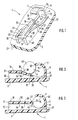
- FIG. 1 shows a spatial representation of the cable holder according to the invention
- FIG. 2 shows a section through the cable holder according to FIG. 1 during the assembly of a cable
- Figure 3 is a section through the cable holder according to Figure 1 with the cable installed.
- 1 denotes a cable holder, which is designed as an independent component or is an integral part of a body 2, for example of the frame of a cooling fan for internal combustion engines is formed.
- the Cable holder 1 and the body 2 separate components, so this in a manner not shown, for example by Gluing, soldering, welding or screwing together connected.
- Cable holder 1 and body 2 can be used different materials. Is the cable holder 1 integral part of the body 2, so as material Plastic used.
- the cable holder 1 has a holding element 5 which for example, has a rectangular cross-section and from Body 2 starting from one away from it extending vertical flat wall 6 and adjoining it has an arcuate wall 7, for example circular runs and describes at least a quarter circle. At the illustrated embodiment runs the arcuate Wall 7 about 120 ° and ends at a free wall end 10, that in the embodiment shown towards Body 2 is inclined.
- An inner wall 11 of the holding element 5 has a flat section 12 in the area of the flat wall 6 and in the area of the arcuate wall 7 an arcuate Section 15.
- the cable holder 1 also has a resilient Retaining tongue 16, the free tongue end 17 on the Holding element 5 is directed towards an end face 20.
- the retaining tongue 16 has a rectangular cross section and extends along a longitudinal axis 21 from a fixed one Tongue end 22 to the free tongue end 17 with a body 2 facing surface 25, a body 2 facing Bottom surface 26 and two cross between surface 25 and Bottom surface 26 extending side surfaces 27. Next to each Side surface 27 runs at a lateral distance from it Guide rail 30.
- the guide rails 30 are the Holding element 5 facing away from each other by a yoke 31 connected.
- each of the guide rails 30 has the body 2 facing away from a guide surface 32, which starts from the yoke 31 a parallel to the surface 25 of the retaining tongue 16 Has parallel section 35 and then in the direction to the holding element 5 to one opposite the surface 25 of the Retaining tongue 16 inclined portion 36 which is for free Tongue end 17 towards the body 2 runs as the lower surface 26 of the retaining tongue 16.
- the guide surface 32nd following the inclined portion 36 into one Abutment section 37 which is parallel to the surface 25 the holding tongue 16 extends to the holding element 5 and thereby compared to the parallel section 35 only one has a small vertical distance from the body 2.
- the contact section 37 also omitted so that the inclined portion 36 each Guide rail 30 extends to the body 2.
- the yoke 31 and the surface 25 of the retaining tongue 16 run in vertical height with a few tenths less Distance to body 2 than the parallel sections 35 of the Guide rails 30.
- the inclined portion 36 of the Guide surface 32 of each guide rail 30 begins approximately in close to the fixed tongue end 22, preferably in one Distance from the fixed tongue end 22, which is about 1/3 to 1/2 the length of the holding tongue 16 in the direction of the longitudinal axis 21 equivalent.
- the vertical distance between the Contact section 37 of the guide surface 32 each Guide rail 30 or the body 2 and the vertical Direction seen highest point of the arcuate Section 15 of the inner wall 11 of the holding element 5 corresponds approximately to the diameter of the cross section of the cable 40th
- the cable holder 1 is in one Assembly situation shown, in which the cable 40 in parallel to the inclined section 36 of the guide rails 30 and the retaining tongue 16 bends towards the body 2. at a further displacement of the cable 40 in the direction of Arrow 41 snaps the cable 40 under the also elastically yielding arcuate wall 7 of the holding element 5 and takes the position shown in Figure 3, in which it is largely comprised by the holding element 5 and the holding tongue 16 bent back into its starting position its end face 20 approximately on the center of the circular cable cross-section is directed. Locks the retaining tab 16 removing the cable 40 from the Cable holder 1.
- First a deliberate turning of the Retaining tongue 16 to the body 2 allows disassembly of the Cable 40 from the cable holder 1.
- Figure 3 is on the free tongue end 17 a transverse to the surface 25 and Tongue nose 42 extending under surface 26 is formed by which a larger end surface 20 is achieved, the cable 40 faces in the assembled state according to FIG.
Landscapes
- Engineering & Computer Science (AREA)
- General Engineering & Computer Science (AREA)
- Mechanical Engineering (AREA)
- Architecture (AREA)
- Civil Engineering (AREA)
- Structural Engineering (AREA)
- Installation Of Indoor Wiring (AREA)
- Insertion, Bundling And Securing Of Wires For Electric Apparatuses (AREA)
Description
Claims (4)
- Kabelhalter (1) zur Fixierung eines Kabels (40) an einem Körper (2), mit einer federelastischen Haltezunge (16) und einem eine Innenwandung (11) aufweisenden Halteelement (5), zu dem hin die Haltezunge (16) mit ihrem freien Zungenende (17) ausgerichtet ist, wobei die Innenwandung (11) mit einem bogenförmigen Abschnitt (15) den Umfang des Kabels (40) bei Benutzung teilweise umgreift, dadurch gekennzeichnet, daß eine Stirnfläche (20) des freien Zungenendes (17) der Haltezunge (16) der Innenwandung (11) des Halteelementes (5) gegenüberliegend etwa auf den Mittelpunkt des kreisförmigen Kabelquerschnittes gerichtet ist, um ein Entfernen des montierten Kabels (40) aus dem Kabelhalter zu sperren.
- Kabelhalter (1) nach Anspruch 1, dadurch gekennzeichnet, daß die Haltezunge (16) sich von einem mit dem Körper (2) verbindbaren festen Zungenende (22) zum freien Zungenende (17) entlang einer Längsachse (21) erstreckt und entlang dieser Längsachse (21) eine dem Körper (2) zugewandte Unterfläche (26), eine dem Körper (2) abgewandte Oberfläche (25) sowie zwei sich quer zwischen Oberfläche (25) und Unterfläche (26) erstreckende Seitenflächen (27) hat und neben jeder Seitenfläche (27) der Haltezunge (16) eine mit dem Körper (2) verbindbare Führungsschiene (30) vorgesehen ist, die eine dem Körper (2) abgewandte Führungsfläche (32) mit einem derart gegenüber der Oberfläche (25) der Haltezunge (16) geneigten Abschnitt (36) hat, daß die Führungsfläche (32) mindestens in Richtung zum freien Zungenende (17) hin mit geringerem Abstand zum Körper (2) verläuft, als die Unterfläche (26) der Haltezunge (16).
- Kabelhalter (1) nach Anspruch 2, dadurch gekennzeichnet, daß der Kabelhalter (1) aus Kunststoff gefertigt ist.
- Körper (2) mit einem Kabelhalter (1) nach Anspruch 3, dadurch gekennzeichnet, daß der Kabelhalter (1) ein integrales Teil des Körpers (2) ist.
Applications Claiming Priority (3)
| Application Number | Priority Date | Filing Date | Title |
|---|---|---|---|
| DE19739151A DE19739151A1 (de) | 1997-09-06 | 1997-09-06 | Kabelhalter |
| DE19739151 | 1997-09-06 | ||
| PCT/DE1998/002004 WO1999013255A1 (de) | 1997-09-06 | 1998-07-17 | Kabelhalter |
Publications (2)
| Publication Number | Publication Date |
|---|---|
| EP0935722A1 EP0935722A1 (de) | 1999-08-18 |
| EP0935722B1 true EP0935722B1 (de) | 2003-05-21 |
Family
ID=7841497
Family Applications (1)
| Application Number | Title | Priority Date | Filing Date |
|---|---|---|---|
| EP98945006A Expired - Lifetime EP0935722B1 (de) | 1997-09-06 | 1998-07-17 | Kabelhalter |
Country Status (6)
| Country | Link |
|---|---|
| US (1) | US6149108A (de) |
| EP (1) | EP0935722B1 (de) |
| JP (1) | JP2001504932A (de) |
| DE (2) | DE19739151A1 (de) |
| ES (1) | ES2200371T3 (de) |
| WO (1) | WO1999013255A1 (de) |
Cited By (1)
| Publication number | Priority date | Publication date | Assignee | Title |
|---|---|---|---|---|
| EP2181292A4 (de) * | 2007-08-29 | 2011-04-20 | Lg Electronics Inc | Klimaanlage |
Families Citing this family (9)
| Publication number | Priority date | Publication date | Assignee | Title |
|---|---|---|---|---|
| FR2811954B1 (fr) * | 2000-07-18 | 2003-01-31 | Ecia Equip Composants Ind Auto | Face avant, bloc avant et vehicule automobile correspondants |
| US6708932B1 (en) * | 2001-11-01 | 2004-03-23 | Charles Gazdik | Cable retainer for sided structure |
| DE102007020681B4 (de) * | 2007-05-03 | 2018-10-31 | Andreas Stihl Ag & Co. Kg | Verbrennungsmotor mit einem Kabelhalter und Kabelhalter für einen Verbrennungsmotor |
| DE102009058118A1 (de) * | 2009-12-12 | 2011-06-16 | Lumberg Connect Gmbh | Anschlussdose für Solarmodule |
| US8651677B2 (en) * | 2010-06-28 | 2014-02-18 | Lexmark International, Inc. | Mounting mechanism for a component of an imaging apparatus, and methods of making and using same |
| FR2982889B1 (fr) * | 2011-11-18 | 2014-02-07 | Plymouth Francaise Sa | Bouche a cle |
| US8844882B2 (en) | 2012-04-13 | 2014-09-30 | Stanley Black & Decker, Inc. | Fastener assisted hanger |
| JP6642028B2 (ja) * | 2016-01-20 | 2020-02-05 | ティアック株式会社 | ケーブルホルダ |
| US20210113815A1 (en) * | 2018-02-27 | 2021-04-22 | 3M Innovative Properties Company | Catheter securement device |
Family Cites Families (6)
| Publication number | Priority date | Publication date | Assignee | Title |
|---|---|---|---|---|
| US2108347A (en) * | 1936-12-07 | 1938-02-15 | Bert L Quarnstrom | Tubing clip |
| US2948940A (en) * | 1957-07-01 | 1960-08-16 | Sperry Rand Corp | Self-locking detachable clamp |
| US3262662A (en) * | 1963-12-09 | 1966-07-26 | Raymond A | Cable fastener |
| DE2440201A1 (de) | 1974-08-22 | 1976-03-04 | Bosch Gmbh Robert | Baueinheit mit einer einen durchbruch aufweisenden halterung und einer mit einem zylindrischen abschnitt in den durchbruch einsteckbaren elektrischen kleinmaschine |
| SE445580B (sv) * | 1979-07-14 | 1986-06-30 | Itw Ltd | Kabelklammer |
| US5639049A (en) * | 1996-05-08 | 1997-06-17 | Jennings; Gilbert M. | Compact cable clip for retainment of cables and tubing |
-
1997
- 1997-09-06 DE DE19739151A patent/DE19739151A1/de not_active Withdrawn
-
1998
- 1998-07-17 EP EP98945006A patent/EP0935722B1/de not_active Expired - Lifetime
- 1998-07-17 ES ES98945006T patent/ES2200371T3/es not_active Expired - Lifetime
- 1998-07-17 DE DE59808447T patent/DE59808447D1/de not_active Expired - Fee Related
- 1998-07-17 WO PCT/DE1998/002004 patent/WO1999013255A1/de not_active Ceased
- 1998-07-17 US US09/297,639 patent/US6149108A/en not_active Expired - Fee Related
- 1998-07-17 JP JP51489999A patent/JP2001504932A/ja active Pending
Cited By (1)
| Publication number | Priority date | Publication date | Assignee | Title |
|---|---|---|---|---|
| EP2181292A4 (de) * | 2007-08-29 | 2011-04-20 | Lg Electronics Inc | Klimaanlage |
Also Published As
| Publication number | Publication date |
|---|---|
| EP0935722A1 (de) | 1999-08-18 |
| DE19739151A1 (de) | 1999-03-11 |
| US6149108A (en) | 2000-11-21 |
| DE59808447D1 (de) | 2003-06-26 |
| WO1999013255A1 (de) | 1999-03-18 |
| JP2001504932A (ja) | 2001-04-10 |
| ES2200371T3 (es) | 2004-03-01 |
Similar Documents
| Publication | Publication Date | Title |
|---|---|---|
| DE2718170C3 (de) | Befestigungsclip für verkleidete Abdeckplatten, insbesondere für Kraftfahrzeuge | |
| EP0612944B1 (de) | Einteiliges Halteelement | |
| DE69308732T2 (de) | Halter für Sonnenblende | |
| EP2003346A2 (de) | Befestigungseinrichtung mit Toleranzausgleich | |
| EP0935722B1 (de) | Kabelhalter | |
| EP4095396B1 (de) | Toleranzausgleichsvorrichtung | |
| DE69301453T2 (de) | Rohrbefestigungsanordnung | |
| EP0936388A1 (de) | Kabelbinder aus Metall | |
| DE3214613A1 (de) | Schwenkbare ornamentanordnung zur anbringung an einer fahrzeugkarosserie | |
| DE102024107214A1 (de) | Befestigungselement | |
| EP0843782A1 (de) | Kraftstoffleitung für kraftstoffördereinrichtungen von kraftfahrzeugen | |
| DE102014203853B4 (de) | Gurtaufroller mit Strafferantrieb | |
| EP1364120B1 (de) | Niederhalteblech zur befestigung eines brennstoffeinspritzventils | |
| DE102020204176A1 (de) | Befestigungselement | |
| DE10114310C2 (de) | Innenverkleidung für ein Fahrzeug | |
| DE69606754T2 (de) | System zum Halten der Position eines Klemmelements | |
| DE102006059096B4 (de) | Baugruppe zur fahrzeugseitigen Befestigung eines Gurtschlosses | |
| WO2020225404A1 (de) | Anschlaganordnung für tilgermassen eines tilgersystems | |
| DE2631402A1 (de) | Wischvorrichtung fuer scheiben von kraftfahrzeugen | |
| DE20305948U1 (de) | Kabelhaltebügel | |
| EP0558791A2 (de) | Bewehrungsanschluss | |
| EP0594143B1 (de) | Verbindungselement | |
| DE3237307C2 (de) | ||
| DE9305934U1 (de) | Einteiliges Halteelement | |
| DE2653294A1 (de) | Verbindungselement eines gestells |
Legal Events
| Date | Code | Title | Description |
|---|---|---|---|
| PUAI | Public reference made under article 153(3) epc to a published international application that has entered the european phase |
Free format text: ORIGINAL CODE: 0009012 |
|
| AK | Designated contracting states |
Kind code of ref document: A1 Designated state(s): DE ES FR GB |
|
| 17P | Request for examination filed |
Effective date: 19990920 |
|
| 17Q | First examination report despatched |
Effective date: 20020125 |
|
| GRAH | Despatch of communication of intention to grant a patent |
Free format text: ORIGINAL CODE: EPIDOS IGRA |
|
| GRAH | Despatch of communication of intention to grant a patent |
Free format text: ORIGINAL CODE: EPIDOS IGRA |
|
| GRAA | (expected) grant |
Free format text: ORIGINAL CODE: 0009210 |
|
| AK | Designated contracting states |
Designated state(s): DE ES FR GB |
|
| PG25 | Lapsed in a contracting state [announced via postgrant information from national office to epo] |
Ref country code: GB Free format text: LAPSE BECAUSE OF FAILURE TO SUBMIT A TRANSLATION OF THE DESCRIPTION OR TO PAY THE FEE WITHIN THE PRESCRIBED TIME-LIMIT Effective date: 20030521 |
|
| REG | Reference to a national code |
Ref country code: GB Ref legal event code: FG4D Free format text: NOT ENGLISH |
|
| RIC1 | Information provided on ipc code assigned before grant |
Ipc: 7H 02G 3/30 B Ipc: 7F 16L 3/13 B Ipc: 7F 16L 3/12 A |
|
| PGFP | Annual fee paid to national office [announced via postgrant information from national office to epo] |
Ref country code: GB Payment date: 20030625 Year of fee payment: 6 |
|
| REF | Corresponds to: |
Ref document number: 59808447 Country of ref document: DE Date of ref document: 20030626 Kind code of ref document: P |
|
| GBV | Gb: ep patent (uk) treated as always having been void in accordance with gb section 77(7)/1977 [no translation filed] |
Effective date: 20030521 |
|
| ET | Fr: translation filed | ||
| REG | Reference to a national code |
Ref country code: ES Ref legal event code: FG2A Ref document number: 2200371 Country of ref document: ES Kind code of ref document: T3 |
|
| PLBE | No opposition filed within time limit |
Free format text: ORIGINAL CODE: 0009261 |
|
| STAA | Information on the status of an ep patent application or granted ep patent |
Free format text: STATUS: NO OPPOSITION FILED WITHIN TIME LIMIT |
|
| 26N | No opposition filed |
Effective date: 20040224 |
|
| PGFP | Annual fee paid to national office [announced via postgrant information from national office to epo] |
Ref country code: ES Payment date: 20070725 Year of fee payment: 10 |
|
| REG | Reference to a national code |
Ref country code: ES Ref legal event code: FD2A Effective date: 20080718 |
|
| PG25 | Lapsed in a contracting state [announced via postgrant information from national office to epo] |
Ref country code: ES Free format text: LAPSE BECAUSE OF NON-PAYMENT OF DUE FEES Effective date: 20080718 |
|
| PGFP | Annual fee paid to national office [announced via postgrant information from national office to epo] |
Ref country code: FR Payment date: 20090720 Year of fee payment: 12 |
|
| PGFP | Annual fee paid to national office [announced via postgrant information from national office to epo] |
Ref country code: DE Payment date: 20090918 Year of fee payment: 12 |
|
| REG | Reference to a national code |
Ref country code: FR Ref legal event code: ST Effective date: 20110331 |
|
| PG25 | Lapsed in a contracting state [announced via postgrant information from national office to epo] |
Ref country code: DE Free format text: LAPSE BECAUSE OF NON-PAYMENT OF DUE FEES Effective date: 20110201 |
|
| REG | Reference to a national code |
Ref country code: DE Ref legal event code: R119 Ref document number: 59808447 Country of ref document: DE Effective date: 20110201 |
|
| PG25 | Lapsed in a contracting state [announced via postgrant information from national office to epo] |
Ref country code: FR Free format text: LAPSE BECAUSE OF NON-PAYMENT OF DUE FEES Effective date: 20100802 |