EP0935489B1 - Dispositif de modification de l'inclinaison laterale d'une chaussure de ski - Google Patents
Dispositif de modification de l'inclinaison laterale d'une chaussure de ski Download PDFInfo
- Publication number
- EP0935489B1 EP0935489B1 EP97950041A EP97950041A EP0935489B1 EP 0935489 B1 EP0935489 B1 EP 0935489B1 EP 97950041 A EP97950041 A EP 97950041A EP 97950041 A EP97950041 A EP 97950041A EP 0935489 B1 EP0935489 B1 EP 0935489B1
- Authority
- EP
- European Patent Office
- Prior art keywords
- ski
- base plate
- boot
- relative
- sliding surface
- Prior art date
- Legal status (The legal status is an assumption and is not a legal conclusion. Google has not performed a legal analysis and makes no representation as to the accuracy of the status listed.)
- Expired - Lifetime
Links
Images


Classifications
-
- A—HUMAN NECESSITIES
- A63—SPORTS; GAMES; AMUSEMENTS
- A63C—SKATES; SKIS; ROLLER SKATES; DESIGN OR LAYOUT OF COURTS, RINKS OR THE LIKE
- A63C9/00—Ski bindings
Definitions
- the invention relates to a device for adjusting a Sideways angle between the ski boot or leg of the Skier and tread of an associated ski.
- a swivel adjustment can often be made on modern ski boots the shoe upper relative to the shoe sole about a shoe longitudinal axis be made.
- an appropriate setting - also called canting setting - can anatomical peculiarities of the skier, e.g. O or X-legs, are compensated in such a way that the treads of the Skis with comfortable leg position on a common level or lie in mutually parallel planes. That way relieved the skier of an undesired tilting of the To avoid skiing.
- ski known from DE 26 03 676 A1 there is between Ski boot and ski arranged a base plate, the shoe side Upper side relative to the lower side on the ski side
- the longitudinal axis of the ski is arranged so that it can be pivoted Swivel adjustment through longitudinal adjustment of wedge elements between the top and bottom of the base plate. Also this enables a canting setting.
- the object of the invention is now to new possibilities Control the tilting of the skis.
- a Adjustment device depending on cornering correlated parameters a parameter-dependent pivoting the ski boot or the boot shaft relative to the tread of the ski around a longitudinal axis of the ski and / or a parameter-dependent one Actuating force causes the shoe or its shaft relatively to pivot sideways to the tread of the ski seeks such that at least one predetermined ski Cornering compared to the sideways inclination of the shoe or leg increased cant and / or increased edge pressure to be led.
- the invention is based on the general idea for a Curving characteristic parameters, in particular the deflection of the skis that occurs when cornering Longitudinal ends when cornering relative to the central area of the Skis are bent in the direction of the vertical axis of the ski Control of a sideways pivoting of the ski boot or his Shaft or to control a corresponding actuating force to be used to at least the edge engagement or edge pressure of a ski when cornering.
- the adjusting device interpret that the increased edge engagement or edge pressure occurs in each case on the outer ski. Basically it is but also possible, a swivel adjustment or positioning force for increased edge engagement or edge pressure on the inside of the curve To effect ski.
- the technique according to the invention is basically also for new or future driving styles suitable.
- the adjusting device can advantageously between Skis and ski bindings can be arranged and for example the Take over the function of a spacer or base plate on which the ski boot is supported with a vertical distance from the top of the ski and held on by a ski binding while skiing is in turn mounted on the spacer or base plate can be.
- the adjustment device is also possible and advantageous to be arranged as part of the ski or with the shoe closed combine.
- the top of the ski depending on parameters in the area of ski bindings or ski boots relative to the skiing surface around a longitudinal axis of the ski be inclined.
- the upper of the ski boot can be depending on the parameter, sideways relative to the shoe sole swing.
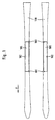
- a pair of skis 100 is shown in plan view, wherein the forward direction of travel is indicated by arrow P.
- Three support zones 101, 102 and 103 are provided on each ski, the support zones 101 and 103 in the longitudinal direction of the ski spaced from each other on the inside of the ski are located while the support zone 102 is on the outside of the ski lies and opposite both support zones 101 and 103 is offset in the longitudinal direction of the ski.
- ski boot 104 trained Base plate 105 may be arranged, which is also the base for in 2 forms ski binding units 120 indicated by dashed lines, with which the ski boot when skiing on the respective Base plate 105 is held.
- Each base plate 105 is now on the associated ski 100 in Area of the support zones 101 to 103 by support elements 106 attached to the ski 100 so that the top of the base plate 105 a greater or lesser distance from the top of the respective ski 100.
- the support members 106 are relative to the base plate 105 and / or relative to the respective one Ski 100 with a certain flexibility arranged such that in the region of the support zones 101 and 103 relative movements between base plate 5 and ski 100 in Ski longitudinal direction and in the region of the support zone 102 in the ski cross direction possible are.
- the skier When cornering, the skier becomes his center of gravity shift more or less towards the inside of the curve, with the result that the ski 100 more or less strong be tilted in such a way that the respective ski axes more or less pronounced towards the inside of the curve.
- the ski 100 will bend according to FIG. 4, i.e. the longitudinal ends of the ski 100 become relative to the central area of the ski 100 bent upwards.
- the support zones 101 to 103 or those corresponding to these support zones 101 to 103 Zones on the underside of the ski or tread of the ski 100 lie on a plane curved in the longitudinal direction of the ski, i.e. in terms of one near the bottom or tread of the ski 100 the support zone 102 lies tangentially contacting plane T. the support zone 102 is deeper than the support zones 101 and 103.
- the base plate 105 changes accordingly 4 and 5 relative to the longitudinal axis of the ski in the lateral direction tilted.
- the support zones 101 to 103 in accordance with a pair of skis Fig. 1 are arranged, it is achieved that the vertical axis of the outer ski more towards the inside of the curve is inclined as the vertical axis of the base plate 105, its inclination determined by the sideways inclination of the skier's legs becomes.
- the result is that with the outer ski one compared to the sideways inclination of the respective leg of the skier significantly increased intervention of the inside of the curve Longitudinal edge of the outer ski reached because the Tilting of this ski towards the inside of the curve can measure the inclination towards the inside of the curve of the skier's leg.
- the invention is not on ski 100 with a deflectable central region limited. Should a ski 100 according to FIG Largely rigid middle area and only flexible Having ski ends, there is the possibility of supporting elements 106 to be provided with a controllable amount and, for example, the Height of the support elements in the area of the support zones 101 and 103 or the height of the support element 106 in the region of the support zone 102 depending on the bending stroke of the front and / or to control the rear end of the ski. Appropriate Constructions are discussed below. In the example of the Fig. 6 is the height controllability of the support elements 106 in Area of the support zones 101 and 103 only by double arrows ⁇ h indicated.
- the display parameters For example, the lateral acceleration of the ski when cornering by means of of a corresponding sensor registered and by active whillemte in a changed relative to the skier's leg Skew cant be implemented. To do this would have to energy storage associated with the respective control elements be carried along.
- Base plate 105 can also be integrated into ski 100, such that the base plate 105 forms part of the top of the ski forms.
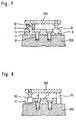
- FIGS. 7 to 10 is below the front and rear ends of the base plate 105 on the Ski each a stable bar 7, preferably made of metal and in particular made of aluminum, fastened by means of screws 8.
- the bar is in the area of the support zones 101 and 103 7 each with a guide 9 parallel to the longitudinal direction of the ski provided, which the head of a screwed into the base plate
- Ball screw 10 slidable in the longitudinal direction of the ski leads and form-fitting vertically and in the direction of the ski holds.
- This ball head screw 10 forms in each case one of the support elements 106 of the base plate 105 at the support zones 101 and 103 (see also FIG. 1).
- a resilient elastomer part 13 On the free end of the pin 11 is a resilient elastomer part 13 attached by means of a hole arranged in it.
- other spring elements e.g. made of metal.
- This bar has in the area of the support zone 102 7 a guide 14 for the head which runs in the direction of the ski a further ball head screw arranged on the base plate 105 10, which is assigned to the support zone 102 2 to 5 forms support element 106.
- a pin 15 is arranged in the bar on which the base plate 105 rests when it is in its position shown in FIG. 8 without inclination in the transverse direction of the ski 100.
- FIGS. 9 and 10 now show the function of the with reference to FIG. 7 and 8 described arrangement when cornering, of which it is assumed that the curve center in the example of Fig. 9 and 10 each lie in the direction of arrow Z and which is shown in FIGS. Skis 100 shown in FIGS. 9 and 10 with respect to the driven curve forms the outer ski. Because of the occurring when cornering The ski 100 now bends sideways the base plate 105 relative to the ski 100, i.e. the Base plate 105 and the ski 100 form in the sectional view 9 and 10 an opening to the curve center Angle. This is equivalent to the base plate 105 in FIG. 9 relative to a transverse axis of the ski 100 around the Angle ⁇ is sloping towards the outside of the curve.
- the ski 100 is relative to the base plate 105 largely without constraint according to the respective Can bend. Only through the bruise the elastomer parts 13 is between the ski 100 and the base plate 105 generates a more or less large restoring force. At the same time, the elastomer parts 13 have a damping effect Bending vibrations of the ski 100.
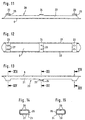
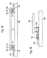
- 11 to 15 is between skis (not shown) and shoe (not shown) one after Adjustment device 20 to be arranged as a spacer plate intended.
- This has a footprint for the shoe as well as a base plate for the assembly of ski binding units 6, on the side walls bent in one piece at right angles Connect 21 and 22.
- the side wall 21 is usually assigned to the inside of a ski while the side wall 22 lies on the outside of the respective ski.
- a fastening strip 24 in one piece molded, which is normally parallel to the Level the base plate 6 aligns.
- This fastening strip too 24 is flexible or flexible with the Side wall 22 connected so that the mounting strip 24 can pivot relative to the plane of the base plate 6.
- the free end of the fastening strip 24 lies in its to the level of the base plate 6 parallel position on one of the Side wall 21 molded stop tabs 26 from below. in the the rest are two round holes 28 in the fastening strip 24 educated.
- the adjusting device 20 is by means of not shown Screws through corresponding recesses 29 in the Stand plate 6 in the elongated holes 27 and the round holes 28 the mounting strips 23 and 24 can be used on the Fixed top of a ski, not shown, the Fastening strips 23 due to the slots 27 relative remain slidable for skiing in the longitudinal direction of the ski.
- Im on the Ski-mounted state of the adjustment device 20 form the Connection areas between the fastening strips 23 and the side wall 21 of the support elements 106 (see FIG. 3) to the Support zones 101 and 103 (see FIG. 1) corresponding supports, during the connection area between the side wall 22 and the fastening strip 24, the support element 106 at the support zone 102 corresponds.
- Stand plate 6 relative to base plate 105 in FIG. 5 relative inclined sideways to the ski.
- This sideways slope is due to the above distance between the stop tabs 25 and the free ends of the fastening strips 23 limited, for example to about 5 °.
- the entire adjustment device 20 described can be made of such material. Suitable materials are, for example, aluminum sheet or plastics. In principle, however, other spring materials are also suitable.
- the space formed between the top of the ski and the base plate 6 can by flexible foam material or Foam rubber or the like completed or completed externally his.
- Support elements are provided on the support zones 101 and 103 controllable height provided, which in the example of FIG. 16 each from a wedge element attached to the base plate 106 108 and a counter wedge that can be moved in the longitudinal direction of the ski 109 exist.
- the counter wedge elements 109 are each via a rod 110 with one on the top of the Front end or rear end of the ski 100 arranged Abutment 111 connected so that the counter wedge elements 109th inevitably in the longitudinal direction of the ski, changing the height that of the respective wedge element 108 and the respective counter-wedge element 109 formed support elements in the longitudinal direction of the ski be moved when the front and rear Ski ends bent relative to the longitudinal central region of the ski 100 become.
- those that work together are Oblique surfaces of the wedge elements 108 and counter wedge elements 109 each inclined so that the height of the elements 108 and 109 supports formed are increased, if the ski ends are upward relative to the center of the ski be bent.
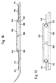
- FIG. 17 differs from that Embodiment of Fig. 16 essentially only in that the rods 110 each to the knee joints of toggle assemblies Connect 112 through the base plate 105 the support zones 101 and 103 (see FIG. 1) opposite the ski 100 is supported and held. If the toggle assemblies 112 when driving straight ahead on a flat slope 17, the vertical Height of toggle assemblies 112 relative to the top of the ski increases when the ski ends are relative to the longitudinal central region of the Skis 100 are bent upwards.
- toggle lever assemblies 112 would normally be theirs Stretched state or the one indicated by dashed lines in FIG. 17 Position would be the vertical height of the toggle assemblies at the aforementioned upward bend of the Reduce ski ends.
- Fig. 19 shows an embodiment in which the base plate 105 on the support zones 101 and 103 (see FIG. 1), respectively is supported by piston-cylinder units 118, each of which is hydraulic with a piston-cylinder unit 119 are connected, the pistons of each of which Rods 110 is operated.
- piston-cylinder units 118 When the ski ends bend upwards relative to the longitudinal central region of the ski 110 Piston-cylinder units 118 inevitably expanded, so that again the cross slope of the base plate 105 relative to the ski 100 is changed accordingly.
- FIGS. 16 to 19 is the vertical height of the supports in the area the support zones 101 and 103 (see FIG. 1) changed. in principle it is also possible to adjust the vertical height of these supports keep constant and the vertical height of the support to change in the area of the support zone 102.
- constructions for height-adjustable supports are used accordingly. With such an arrangement only needs a single bar 110 on the front or to be placed at the rear end of the ski 100 since each only the vertical height of a single support changes must become.
- the variants shown in FIGS. 16 to 19 can be modified in that the unchangeable height Support of the base plate 105 in the area of the support zone 102 (see Fig. 1) omitted and by two unchangeable height Outriggers is replaced on the outrigger zones 101 and 103 opposite long side of the ski 100 as much as possible, especially about each other the support zones 101 and 103 can be arranged.
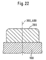
- the upper of the ski boot has a sideways inclination indicated by line 300, which is less than that of the vertical axis 400 of the ski 100 sideways inclination.
Landscapes
- Footwear And Its Accessory, Manufacturing Method And Apparatuses (AREA)
Claims (10)
- Dispositif pour régler un angle dans la direction latérale entre la chaussure de ski ou la jambe du skieur et la surface de glisse d'un ski associé,
caractérisé par
un dispositif de réglage, qui provoque, en fonction de paramètres corrélés à des descentes en virage, les paramètres étant des accélérations transversales ou des flexions du ski se produisant en descente en virage, un pivotement, en fonction des paramètres, de la chaussure de ski ou de la tige de la chaussure par rapport à la surface de glisse du ski (100) autour d'un axe longitudinal du ski et/ou une force de réglage dépendant des paramètres, qui a tendance à faire pivoter la chaussure ou sa tige par rapport à la surface de glisse du ski dans la direction latérale, de telle sorte qu'au moins un ski prédéfini soit guidé, en descente en virage, avec un basculement accru par comparaison avec une inclinaison latérale de la chaussure de ski ou de la jambe. - Dispositif selon la revendication 1,
caractérisé en ce qu'
une flexion du ski respectif se produisant en descente en virage - au moins dans le cas d'une position oblique inclinée du skieur ou de sa jambe par rapport au côté intérieur du virage - commande par le biais du dispositif de réglage un basculement latéral de la chaussure de ski ou de sa tige par rapport au ski associé, de telle sorte que l'axe vertical de la surface de glisse du ski prédéfini, notamment du ski extérieur au virage, soit plus incliné vers le côté intérieur du virage que l'axe vertical de la chaussure de ski associée ou de sa tige. - Dispositif selon la revendication 1 ou 2,
caractérisé en ce que
le dispositif de réglage (105, 106 ; 6, 10, 9, 14 ; 105, 108 à 119) est disposé sur le ski. - Dispositif selon la revendication 3,
caractérisé en ce que
le dispositif de réglage est disposé entre le ski et la chaussure de ski ou la fixation de ski. - Dispositif selon l'une quelconque des revendications 1 à 4,
caractérisé en ce que
l'on prévoit sur le ski une plaque de support ou de base (6, 105) qui est maintenue verticalement sur un côté longitudinal du ski (100) au niveau de deux zones de support (101, 103) espacées l'une de l'autre dans la direction longitudinale du ski et sur l'autre côté longitudinal du ski au niveau d'une autre zone de support (102) décalée dans la direction longitudinale du ski par rapport aux deux zones de support susmentionnées, de sorte que des flexions du ski dans la région des zones de support (101, 102, 103) conduisent à une inclinaison transversale ou à une modification de l'inclinaison transversale de la plaque de base par rapport au ski. - Dispositif selon l'une quelconque des revendications 1 à 5,
caractérisé en ce que
l'on dispose sur le ski (100) une plaque de support ou de base (6, 105) qui est maintenue verticalement essentiellement fixement sur un côté longitudinal du ski et qui est maintenue avec une possibilité de réglage vertical en hauteur sur l'autre côté longitudinal du ski, le réglage en hauteur étant prédéfini par des paramètres corrélés aux descentes en virage. - Dispositif selon la revendication 6,
caractérisé en ce que
le réglage en hauteur peut être commandé en fonction de flexions du ski (100) ou de parties du ski (extrémité avant du ski, extrémité arrière du ski). - Dispositif selon l'une quelconque des revendications 1 à 7,
caractérisé en ce que
l'on dispose entre la plaque de support ou de base (6, 105) et le ski (100) ou des parties du ski des éléments de ressort (13) qui pressent la plaque de support ou de base dans une position normale par rapport au ski. - Dispositif selon l'une quelconque des revendications 1 à 8,
caractérisé en ce que
le pivotement de la chaussure de ski ou de la tige de la chaussure en fonction de paramètres par rapport à la surface de glisse du ski (100) est compris dans une plage d'environ 0° à 10°. - Dispositif selon la revendication 9,
caractérisé en ce que
le pivotement maximum est limité à environ 5°.
Applications Claiming Priority (5)
| Application Number | Priority Date | Filing Date | Title |
|---|---|---|---|
| CH268596 | 1996-10-31 | ||
| CH268596 | 1996-10-31 | ||
| CH202997 | 1997-08-29 | ||
| CH202997 | 1997-08-29 | ||
| PCT/EP1997/005970 WO1998018528A1 (fr) | 1996-10-31 | 1997-10-29 | Dispositif de modification de l'inclinaison laterale d'une chaussure de ski |
Publications (2)
| Publication Number | Publication Date |
|---|---|
| EP0935489A1 EP0935489A1 (fr) | 1999-08-18 |
| EP0935489B1 true EP0935489B1 (fr) | 2004-05-19 |
Family
ID=25689319
Family Applications (1)
| Application Number | Title | Priority Date | Filing Date |
|---|---|---|---|
| EP97950041A Expired - Lifetime EP0935489B1 (fr) | 1996-10-31 | 1997-10-29 | Dispositif de modification de l'inclinaison laterale d'une chaussure de ski |
Country Status (5)
| Country | Link |
|---|---|
| US (1) | US6149182A (fr) |
| EP (1) | EP0935489B1 (fr) |
| AT (1) | ATE267035T1 (fr) |
| DE (1) | DE59711646D1 (fr) |
| WO (1) | WO1998018528A1 (fr) |
Families Citing this family (6)
| Publication number | Priority date | Publication date | Assignee | Title |
|---|---|---|---|---|
| FR2804337B1 (fr) * | 2000-01-28 | 2002-03-08 | Rossignol Sa | Ski alpin |
| JP2002035197A (ja) * | 2000-07-24 | 2002-02-05 | Aki International:Kk | スノーボード |
| US7874591B2 (en) | 2005-11-12 | 2011-01-25 | Biostance Llc | Apparatus and method for canting a skier |
| US8448990B2 (en) | 2005-11-12 | 2013-05-28 | Biostance, Llc | Apparatus and method for ramping and/or canting a skier |
| NO2715057T3 (fr) * | 2014-04-02 | 2018-02-10 | ||
| DE102014108284A1 (de) * | 2014-06-12 | 2015-12-17 | Willi Kehl | Skating-Ski |
Family Cites Families (9)
| Publication number | Priority date | Publication date | Assignee | Title |
|---|---|---|---|---|
| DE2255406A1 (de) * | 1972-11-11 | 1974-05-16 | Wolf Dieter Hellmann | Vorrichtung zur zuordnung der fussaufstellflaeche zu skiern |
| DE2603676A1 (de) * | 1976-01-31 | 1977-08-04 | Kammerl | Verbindung von skibindung und ski |
| US4141570A (en) * | 1977-10-17 | 1979-02-27 | Sudmeier James L | Adjustable connection between ski and binding |
| CH671887A5 (fr) * | 1982-03-25 | 1989-10-13 | Brosi Bettosini | |
| US5026087A (en) * | 1988-07-27 | 1991-06-25 | Wulf Elmer B | Ski boot and ski boot-binding |
| FR2673546B1 (fr) * | 1991-03-06 | 1993-12-17 | Lauzier Ets | Fixation pour surf de neige. |
| US5412883A (en) * | 1993-07-12 | 1995-05-09 | Wulf Elmer Bernard | Ski boot and ski boot-bindings |
| US5671939A (en) * | 1995-03-10 | 1997-09-30 | Pineau; David G. | Binding mount assembly for an alpine ski |
| US5785342A (en) * | 1996-07-30 | 1998-07-28 | Bronson; Henry D. | Ski binding dampening assembly |
-
1997
- 1997-10-29 DE DE59711646T patent/DE59711646D1/de not_active Expired - Fee Related
- 1997-10-29 US US09/297,247 patent/US6149182A/en not_active Expired - Fee Related
- 1997-10-29 WO PCT/EP1997/005970 patent/WO1998018528A1/fr active IP Right Grant
- 1997-10-29 AT AT97950041T patent/ATE267035T1/de not_active IP Right Cessation
- 1997-10-29 EP EP97950041A patent/EP0935489B1/fr not_active Expired - Lifetime
Also Published As
| Publication number | Publication date |
|---|---|
| EP0935489A1 (fr) | 1999-08-18 |
| DE59711646D1 (de) | 2004-06-24 |
| ATE267035T1 (de) | 2004-06-15 |
| WO1998018528A1 (fr) | 1998-05-07 |
| US6149182A (en) | 2000-11-21 |
Similar Documents
| Publication | Publication Date | Title |
|---|---|---|
| DE69015485T2 (de) | Zusatzvorrichtung zum Ski zur Montage eines Paares Skibindungen auf dem Ski. | |
| AT401351B (de) | Verbindungseinrichtung zum halten eines schischuhes auf einem schi | |
| EP0635286B1 (fr) | Planche de glisse | |
| AT403891B (de) | Tragplatte zur halterung eines skischuhes auf einem ski | |
| DE69208895T2 (de) | Vorrichtung zum verändern der natürlichen druckverteilung eines skis auf einer gleitfläche | |
| DE69612268T2 (de) | Gleitbrett mit Versteifungsvorrichtung | |
| DE3020346C2 (fr) | ||
| DE69215692T2 (de) | Einrichtung zur druckverteilung eines schis auf der gleitläche | |
| DE29608903U1 (de) | Vorrichtung zur Aufnahme einer Skibindung auf einem Ski und mit einer derartigen Vorrichtung ausgerüsteter Ski | |
| DE29824950U1 (de) | Skibindung | |
| EP0151975B1 (fr) | Cross-country ski | |
| EP1297869B1 (fr) | Planche de glisse ,speciallement un ski | |
| EP0935489B1 (fr) | Dispositif de modification de l'inclinaison laterale d'une chaussure de ski | |
| DE19836515A1 (de) | Verteilungsvorrichtung für auf ein Sportgerät zu übertragende Belastungen und/oder Kräfte sowie Sportgerät hierfür | |
| AT395115B (de) | Bindung fuer langlaufski | |
| DE69216860T2 (de) | Vorrichtung zum verändern der natürlichen druckverteilung eines skis auf seinegleitfläche | |
| DE3223413A1 (de) | Ski | |
| DE3334488A1 (de) | Vorrichtung zum verhindern des zurueckgleitens eines skis | |
| DE69604350T2 (de) | Gleitbrett mit Plattform zur Aufnahme und Erhöhung der Skibindung | |
| DE10152438B4 (de) | Schneegleitbrett, insbesondere Ski sowie Spreizvorrichtung für ein Schneegleitbrett | |
| EP2872225B1 (fr) | Unité de liaison | |
| DE69402937T2 (de) | Schischuh | |
| DE3838586A1 (de) | Seitliche fuehrungsvorrichtung eines schuhs auf einem langlaufski | |
| DE69601834T2 (de) | Übungsmittel zum Erlernen des Skilanglaufs nach der Schlittschuhlaufschritttechnik | |
| EP0857500A2 (fr) | Dispositif pour le montage d'une fixation de ski |
Legal Events
| Date | Code | Title | Description |
|---|---|---|---|
| PUAI | Public reference made under article 153(3) epc to a published international application that has entered the european phase |
Free format text: ORIGINAL CODE: 0009012 |
|
| 17P | Request for examination filed |
Effective date: 19990414 |
|
| AK | Designated contracting states |
Kind code of ref document: A1 Designated state(s): AT CH DE FR IT LI |
|
| 17Q | First examination report despatched |
Effective date: 20021122 |
|
| GRAP | Despatch of communication of intention to grant a patent |
Free format text: ORIGINAL CODE: EPIDOSNIGR1 |
|
| GRAS | Grant fee paid |
Free format text: ORIGINAL CODE: EPIDOSNIGR3 |
|
| GRAA | (expected) grant |
Free format text: ORIGINAL CODE: 0009210 |
|
| AK | Designated contracting states |
Kind code of ref document: B1 Designated state(s): AT CH DE FR IT LI |
|
| PG25 | Lapsed in a contracting state [announced via postgrant information from national office to epo] |
Ref country code: IT Free format text: LAPSE BECAUSE OF FAILURE TO SUBMIT A TRANSLATION OF THE DESCRIPTION OR TO PAY THE FEE WITHIN THE PRE;WARNING: LAPSES OF ITALIAN PATENTS WITH EFFECTIVE DATE BEFORE 2007 MAY HAVE OCCURRED AT ANY TIME BEFORE 2007. THE CORRECT EFFECTIVE DATE MAY BE DIFFERENT FROM THE ONE RECORDED.SCRIBED TIME-LIMIT Effective date: 20040519 Ref country code: FR Free format text: LAPSE BECAUSE OF FAILURE TO SUBMIT A TRANSLATION OF THE DESCRIPTION OR TO PAY THE FEE WITHIN THE PRESCRIBED TIME-LIMIT Effective date: 20040519 |
|
| REG | Reference to a national code |
Ref country code: CH Ref legal event code: EP |
|
| REF | Corresponds to: |
Ref document number: 59711646 Country of ref document: DE Date of ref document: 20040624 Kind code of ref document: P |
|
| PG25 | Lapsed in a contracting state [announced via postgrant information from national office to epo] |
Ref country code: LI Free format text: LAPSE BECAUSE OF NON-PAYMENT OF DUE FEES Effective date: 20041031 Ref country code: CH Free format text: LAPSE BECAUSE OF NON-PAYMENT OF DUE FEES Effective date: 20041031 |
|
| PLBE | No opposition filed within time limit |
Free format text: ORIGINAL CODE: 0009261 |
|
| STAA | Information on the status of an ep patent application or granted ep patent |
Free format text: STATUS: NO OPPOSITION FILED WITHIN TIME LIMIT |
|
| 26N | No opposition filed |
Effective date: 20050222 |
|
| EN | Fr: translation not filed | ||
| REG | Reference to a national code |
Ref country code: CH Ref legal event code: PL |
|
| PGFP | Annual fee paid to national office [announced via postgrant information from national office to epo] |
Ref country code: AT Payment date: 20061024 Year of fee payment: 10 |
|
| PGFP | Annual fee paid to national office [announced via postgrant information from national office to epo] |
Ref country code: DE Payment date: 20061107 Year of fee payment: 10 |
|
| PG25 | Lapsed in a contracting state [announced via postgrant information from national office to epo] |
Ref country code: DE Free format text: LAPSE BECAUSE OF NON-PAYMENT OF DUE FEES Effective date: 20080501 |
|
| PG25 | Lapsed in a contracting state [announced via postgrant information from national office to epo] |
Ref country code: AT Free format text: LAPSE BECAUSE OF NON-PAYMENT OF DUE FEES Effective date: 20071029 |