EP0934839A2 - Einzelradaufhängung für nichtgelenkte Räder von Kraftfahrzeugen - Google Patents
Einzelradaufhängung für nichtgelenkte Räder von Kraftfahrzeugen Download PDFInfo
- Publication number
- EP0934839A2 EP0934839A2 EP99102240A EP99102240A EP0934839A2 EP 0934839 A2 EP0934839 A2 EP 0934839A2 EP 99102240 A EP99102240 A EP 99102240A EP 99102240 A EP99102240 A EP 99102240A EP 0934839 A2 EP0934839 A2 EP 0934839A2
- Authority
- EP
- European Patent Office
- Prior art keywords
- shock absorber
- spring
- opening
- wheel suspension
- independent
- Prior art date
- Legal status (The legal status is an assumption and is not a legal conclusion. Google has not performed a legal analysis and makes no representation as to the accuracy of the status listed.)
- Granted
Links
- 239000000725 suspension Substances 0.000 title claims description 22
- 239000006096 absorbing agent Substances 0.000 claims abstract description 38
- 230000035939 shock Effects 0.000 claims abstract description 38
- 230000006835 compression Effects 0.000 claims 1
- 238000007906 compression Methods 0.000 claims 1
- ATJFFYVFTNAWJD-UHFFFAOYSA-N Tin Chemical compound [Sn] ATJFFYVFTNAWJD-UHFFFAOYSA-N 0.000 description 5
- 230000001419 dependent effect Effects 0.000 description 1
- 230000000694 effects Effects 0.000 description 1
- 238000009434 installation Methods 0.000 description 1
Images

Classifications
-
- B—PERFORMING OPERATIONS; TRANSPORTING
- B60—VEHICLES IN GENERAL
- B60G—VEHICLE SUSPENSION ARRANGEMENTS
- B60G15/00—Resilient suspensions characterised by arrangement, location or type of combined spring and vibration damper, e.g. telescopic type
- B60G15/02—Resilient suspensions characterised by arrangement, location or type of combined spring and vibration damper, e.g. telescopic type having mechanical spring
- B60G15/06—Resilient suspensions characterised by arrangement, location or type of combined spring and vibration damper, e.g. telescopic type having mechanical spring and fluid damper
- B60G15/062—Resilient suspensions characterised by arrangement, location or type of combined spring and vibration damper, e.g. telescopic type having mechanical spring and fluid damper the spring being arranged around the damper
-
- B—PERFORMING OPERATIONS; TRANSPORTING
- B60—VEHICLES IN GENERAL
- B60G—VEHICLE SUSPENSION ARRANGEMENTS
- B60G3/00—Resilient suspensions for a single wheel
- B60G3/18—Resilient suspensions for a single wheel with two or more pivoted arms, e.g. parallelogram
- B60G3/20—Resilient suspensions for a single wheel with two or more pivoted arms, e.g. parallelogram all arms being rigid
- B60G3/202—Resilient suspensions for a single wheel with two or more pivoted arms, e.g. parallelogram all arms being rigid having one longitudinal arm and two parallel transversal arms, e.g. dual-link type strut suspension
Definitions
- the invention relates to an independent wheel suspension for non-steered wheels of motor vehicles, especially of passenger cars, according to the preamble of Claim 1.
- This Independent suspension consists of two wishbones arranged one above the other hinged at one end to a wheel carrier.
- the body ends of the Wishbones are forward in the vehicle's longitudinal direction. H. to the front end of the Motor vehicle, directed and articulated to a vehicle body or Subframe or the like arranged.
- One end of a trailing arm is as one Wheel carrier trained.
- the opposite end of the trailing arm is hinged to the vehicle body or the like via an elastic bearing.
- On the upper wishbone is supported by a lower end of a spring.
- Of the Shock absorber is behind the wheel center and behind a drive shaft in the direction Rear of the vehicle arranged.
- the object of the invention is to provide independent suspension for non-steered wheels To create motor vehicles that have relatively little space with a high level of driving comfort required.
- the lower end of the shock absorber in the vehicle longitudinal direction to the front end of the motor vehicle the wheel center and in front of a drive shaft by the shock absorber an opening formed in the upper wishbone and passed through the spring is.
- the installation length of the shock absorber significantly shorter, so that a protruding into the trunk Damper dome is lower and thus advantageously the loading width and the trunk volume of the provided with the independent wheel suspension according to the invention Motor vehicle increased.
- the translation i of the shock absorber i approx. 0.7.
- the loading width of a trunk then increases depending on the embodiment the body structure by about 10%.
- the increase in the trunk volume when using the independent wheel suspension according to the invention is around 5%.
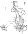
- Fig. 1 shows an independent suspension 1 for not shown, not steered Wheels of a motor vehicle.
- the independent wheel suspension 1 has a trailing arm 2, an upper and a lower wishbone 3 and 4.
- In the upper wishbone 3 is an opening 5 shown in FIGS. 2 and 3 through which a Shock absorber 6 is passed.
- a spring 7 is between a tin pot 34 or the like and the upper wishbone 3.
- the tin pot 34 is on a body 11 attached.
- the independent suspension 1 is correct except for the change in the arrangement of the Shock absorber 6 with that described in ATZ 93 (1991), pages 274 to 280 "Central link rear axle" match. To avoid repetitions referred to the features described there.
- the trailing arm 2 is elastic at one end 9 via a bearing 10 on the Tied body 11.
- the opposite end 12 of the trailing arm 2 is designed as a wheel carrier 13.
- the one above the other Wishbones 3 and 4 are at their respective one ends 14, 15 at one Subframe 16 shown in detail is articulated elastically via rubber bearings.
- the one opposite ends 17, 18 of the wishbones 3, 4 are with joints 19, 20 with connected to the wheel carrier 13.
- the upper end 8 of the shock absorber 6 is inside the tin pot 34 and arranged via an elastic bearing 21, in particular a Rubber bearing, connected to the tin pot 34.
- a lower end 22 of the shock absorber 6 is articulated on the trailing arm 2 so that the lower end 22 in comparison to the upper end 8 of the shock absorber 6 to the front in the vehicle longitudinal direction 32 is shifted and the shock absorber 6 has a corresponding inclination.
- the spring 7 is supported with its upper end 23 on the tin pot 34.
- a lower end 24 of the spring 7 is arranged on the upper wishbone 3.
- Fig. 1 are also individual, acting in the vertical direction forces F L , F Se , F Sa , F R and F F and individual distances or lever arms a e , a a , b, c e , c a and d between the forces mentioned.
- the footnotes e or a each relate to the sprung-in or sprung-out state 28, 29 of the lower end 22 of the shock absorber 6. Accordingly, the center line 30 of the shock absorber 6 is provided with the footnotes e and a.
- the shock absorber 6 shown in solid lines and the center line 30 without a footnote shows a deflection position of the wheel suspension 1, which lies between the fully sprung-in and spring-out state.
- F L is a force to be absorbed by the bearing 11.
- F Se and F Sa are each a force acting on the lower end 22 of the shock absorber 6 in the spring-loaded or spring-loaded state 28, 29.
- F R denotes a force supported in the wheel center 33 by the wheel carrier 13.
- the spring 7 is due to the Space requirement of the shock absorber 6 designed as a conical spring when deflected.
- Out 1 is also a through hole 25 at the level of a wheel center 33 in the wheel carrier 13 for a drive shaft 27 shown in FIGS. 2 and 3.
- the position of the brake caliper 26 can be seen in FIG. 1.
- FIG. 2 From the top view of FIG. 2 is that for supporting the lower end 24 of the spring 7 widened surface of the upper wishbone 3 can be seen.
- the one in the top Wishbone 3 formed opening 5 is according to the space requirement of the shock absorber 6 elongated when deflected, as is partly due to the dotted line is shown in FIG. 2.
- 2 is the position of the shock absorber 6 in the sprung position 28 and in the sprung position 29 using in each case a center line 30e and 30a of the shock absorber 6 and a double arrow 31 shown.
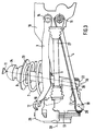
- control arms 3 and 4 one above the other can be seen from FIG. In dotted lines, the transverse extension of the trailing arm 2 is shown. Further goes 3 that the shock absorber 6 is relatively short. The wheel suspension 1 is in a state of deflection between the fully sprung and resilient condition.
Landscapes
- Engineering & Computer Science (AREA)
- Mechanical Engineering (AREA)
- Vehicle Body Suspensions (AREA)
Abstract
Description
Claims (4)
- Einzelradaufhängung für nichtgelenkte Räder eines Kraftfahrzeuges, mit einem Radträger, an dem zwei übereinander angeordnete Querlenker angelenkt sind, deren aufbauseitige Enden in Fahrzeuglängsrichtung nach vorne gerichtet sind und die jeweils an einem Fahrzeugaufbau oder einem Fahrschemel über ein Gelenk angeordnet sind, mit einem Längslenker, bei dem das eine Ende als Radträger ausgebildet ist und das andere Ende über ein elastisches Lager am Fahrzeugaufbau oder dergleichen angelenkt ist, wobei sich auf dem oberen Querlenker ein unteres Ende einer Feder abstützt, und mit einem Stoßdämpfer,
dadurch gekennzeichnet, daß der obere Querlenker (3) eine Durchgangsöffnung (5) aufweist, daß durch die Feder (7) und die Durchgangsöffnung (5) des oberen Querlenkers (3) der Stoßdämpfer (6) hindurchgeführt ist, dessen unteres Ende (22) in Fahrzeuglängsrichtung (32) zwischen einer Radmitte (33) und dem aufbauseitigen Ende (9) des Längslenkers (2) angelenkt ist, daß die Form und Größe der Durchgangsöffnung (5) und der Feder (7) dem Raumbedarf des Stoßdämpfers (6) beim Ein- und Ausfedern angepaßt ist. - Einzelradaufhängung nach Anspruch 1,
dadurch gekennzeichnet, daß das untere Ende (22) des jeweiligen Stoßdämpfers (6) vor je einer Antriebswelle (27) angeordnet ist. - Einzelradaufhängung nach den Ansprüchen 1 oder 2,
dadurch gekennzeichnet, daß die Feder (7) kegelförmig ist und daß das untere Ende (24) der Feder (7) einen größeren Durchmesser als die Durchgangsöffnung (5) aufweist. - Einzelradaufhängung nach einem der vorhergehenden Ansprüche,
dadurch gekennzeichnet, daß die Übersetzung i des Stoßdämpfers (6) i < 1 ist.
Applications Claiming Priority (2)
| Application Number | Priority Date | Filing Date | Title |
|---|---|---|---|
| DE19804699 | 1998-02-06 | ||
| DE1998104699 DE19804699A1 (de) | 1998-02-06 | 1998-02-06 | Einzelradaufhängung für nichtgelenkte Räder von Kraftfahrzeugen |
Publications (3)
| Publication Number | Publication Date |
|---|---|
| EP0934839A2 true EP0934839A2 (de) | 1999-08-11 |
| EP0934839A3 EP0934839A3 (de) | 2003-10-08 |
| EP0934839B1 EP0934839B1 (de) | 2006-05-03 |
Family
ID=7856825
Family Applications (1)
| Application Number | Title | Priority Date | Filing Date |
|---|---|---|---|
| EP19990102240 Expired - Lifetime EP0934839B1 (de) | 1998-02-06 | 1999-02-04 | Einzelradaufhängung für nichtgelenkte Räder von Kraftfahrzeugen |
Country Status (2)
| Country | Link |
|---|---|
| EP (1) | EP0934839B1 (de) |
| DE (2) | DE19804699A1 (de) |
Cited By (3)
| Publication number | Priority date | Publication date | Assignee | Title |
|---|---|---|---|---|
| EP1074407A3 (de) * | 1999-07-31 | 2004-12-29 | Bayerische Motoren Werke Aktiengesellschaft | Einzelradaufhängung für nichtgelenkte Räder eines Kraftfahrzeuges |
| CN102407746A (zh) * | 2011-10-09 | 2012-04-11 | 中国农业大学 | 扭杆弹簧汽车独立悬架 |
| US20240065148A1 (en) * | 2017-01-04 | 2024-02-29 | Briggs & Stratton Llc | Outdoor power equipment suspension system |
Family Cites Families (6)
| Publication number | Priority date | Publication date | Assignee | Title |
|---|---|---|---|---|
| US3039788A (en) * | 1959-09-30 | 1962-06-19 | Farago Paul | Steerable wheel vehicle suspension arrangement |
| US3193302A (en) * | 1962-04-18 | 1965-07-06 | Harry Fergnson Res Ltd | Rear suspension mechanism for motor vehicles |
| US3193304A (en) * | 1963-12-23 | 1965-07-06 | Ford Motor Co | Vehicle suspension system having an articulated spring support |
| DE4129643C2 (de) * | 1991-09-06 | 1996-01-18 | Bayerische Motoren Werke Ag | Einzelradaufhängung für nichtgelenkte Räder von Kraftfahrzeugen, insbesondere von Personenkraftwagen |
| DE4206896C2 (de) * | 1992-03-05 | 1994-09-01 | Bayerische Motoren Werke Ag | Radaufhängung für lenkbare Räder von Kraftfahrzeugen |
| DE19509470A1 (de) * | 1995-03-16 | 1996-09-19 | Porsche Ag | Radaufhängung |
-
1998
- 1998-02-06 DE DE1998104699 patent/DE19804699A1/de not_active Withdrawn
-
1999
- 1999-02-04 EP EP19990102240 patent/EP0934839B1/de not_active Expired - Lifetime
- 1999-02-04 DE DE59913375T patent/DE59913375D1/de not_active Expired - Lifetime
Non-Patent Citations (1)
| Title |
|---|
| ATZ 93, 1991, pages 274 - 280 |
Cited By (4)
| Publication number | Priority date | Publication date | Assignee | Title |
|---|---|---|---|---|
| EP1074407A3 (de) * | 1999-07-31 | 2004-12-29 | Bayerische Motoren Werke Aktiengesellschaft | Einzelradaufhängung für nichtgelenkte Räder eines Kraftfahrzeuges |
| CN102407746A (zh) * | 2011-10-09 | 2012-04-11 | 中国农业大学 | 扭杆弹簧汽车独立悬架 |
| US20240065148A1 (en) * | 2017-01-04 | 2024-02-29 | Briggs & Stratton Llc | Outdoor power equipment suspension system |
| US12370849B2 (en) * | 2017-01-04 | 2025-07-29 | Briggs & Stratton, Llc | Outdoor power equipment suspension system |
Also Published As
| Publication number | Publication date |
|---|---|
| EP0934839A3 (de) | 2003-10-08 |
| EP0934839B1 (de) | 2006-05-03 |
| DE59913375D1 (de) | 2006-06-08 |
| DE19804699A1 (de) | 1999-08-12 |
Similar Documents
| Publication | Publication Date | Title |
|---|---|---|
| DE3048794C1 (de) | Unabhaengige Radaufhaengung fuer Kraftfahrzeuge | |
| DE60119217T2 (de) | Radaufhängung für ein Fahrzeug | |
| DE3243434C2 (de) | Unabhängige Radaufhängung für die Hinterräder eines Kraftfahrzeuges | |
| EP1428698A1 (de) | Achsaufhängung für Starrachsen in Fahrzeugen | |
| DE3434790A1 (de) | Hinterradaufhaengung fuer ein kraftfahrzeug | |
| WO2003008212A1 (de) | Hinterachse eines personenkraftwagens mit fünf einzelnen lenkern | |
| DE102010036681A1 (de) | Lenkerarm eines Mehrlenkeraufhängungssystems eines Fahrzeuges | |
| DE4129643C2 (de) | Einzelradaufhängung für nichtgelenkte Räder von Kraftfahrzeugen, insbesondere von Personenkraftwagen | |
| DE3441560C2 (de) | ||
| WO2007087797A1 (de) | Radaufhängung für ein kraftfahrzeug | |
| DE4203057A1 (de) | Radaufhaengung fuer fahrzeuge | |
| DE69320325T2 (de) | Fahrzeugaufhängungssystem | |
| DE19721753B4 (de) | Radaufhängung für Kraftfahrzeuge | |
| EP1145877B1 (de) | Radaufhängung | |
| DE69225225T2 (de) | Fahrzeugaufhängung | |
| DE102007005967A1 (de) | Radaufhängung für Kraftfahrzeuge | |
| DE3529642A1 (de) | Anordnung fuer den einbau eines stabilisators in eine fahrzeugaufhaengung | |
| EP0202449B1 (de) | Unabhängige Fahrzeug-Radaufhängung | |
| WO2023025542A1 (de) | Radaufhängung eines fahrzeuges | |
| DE2439365C3 (de) | Radaufhängung für Kraftfahrzeuge, insbesondere für Personenkraftwagen | |
| DE102005056835B3 (de) | Seiten-Ankopplungsvorrichtung für Fahrzeug-Aufhängungsvorrichtungen | |
| EP0934839B1 (de) | Einzelradaufhängung für nichtgelenkte Räder von Kraftfahrzeugen | |
| DE4427172A1 (de) | Radaufhängung, insbesondere Hinterachsaufhängung für Nutzfahrzeuge | |
| DE3012873A1 (de) | Daempferbein-achse fuer personenkraftwagen | |
| DE3524763C2 (de) | Kraftfahrzeug-Hinterachse, insbesondere für Personenkraftwagen |
Legal Events
| Date | Code | Title | Description |
|---|---|---|---|
| PUAI | Public reference made under article 153(3) epc to a published international application that has entered the european phase |
Free format text: ORIGINAL CODE: 0009012 |
|
| AK | Designated contracting states |
Kind code of ref document: A2 Designated state(s): AT BE CH CY DE DK ES FI FR GB GR IE IT LI LU MC NL PT SE |
|
| AX | Request for extension of the european patent |
Free format text: AL;LT;LV;MK;RO;SI |
|
| PUAL | Search report despatched |
Free format text: ORIGINAL CODE: 0009013 |
|
| AK | Designated contracting states |
Kind code of ref document: A3 Designated state(s): AT BE CH CY DE DK ES FI FR GB GR IE IT LI LU MC NL PT SE |
|
| AX | Request for extension of the european patent |
Extension state: AL LT LV MK RO SI |
|
| 17P | Request for examination filed |
Effective date: 20031018 |
|
| AKX | Designation fees paid |
Designated state(s): DE FR GB |
|
| GRAP | Despatch of communication of intention to grant a patent |
Free format text: ORIGINAL CODE: EPIDOSNIGR1 |
|
| GRAS | Grant fee paid |
Free format text: ORIGINAL CODE: EPIDOSNIGR3 |
|
| GRAA | (expected) grant |
Free format text: ORIGINAL CODE: 0009210 |
|
| AK | Designated contracting states |
Kind code of ref document: B1 Designated state(s): DE FR GB |
|
| REG | Reference to a national code |
Ref country code: GB Ref legal event code: FG4D Free format text: NOT ENGLISH |
|
| REF | Corresponds to: |
Ref document number: 59913375 Country of ref document: DE Date of ref document: 20060608 Kind code of ref document: P |
|
| GBT | Gb: translation of ep patent filed (gb section 77(6)(a)/1977) |
Effective date: 20060518 |
|
| ET | Fr: translation filed | ||
| PLBE | No opposition filed within time limit |
Free format text: ORIGINAL CODE: 0009261 |
|
| STAA | Information on the status of an ep patent application or granted ep patent |
Free format text: STATUS: NO OPPOSITION FILED WITHIN TIME LIMIT |
|
| 26N | No opposition filed |
Effective date: 20070206 |
|
| REG | Reference to a national code |
Ref country code: FR Ref legal event code: PLFP Year of fee payment: 18 |
|
| PGFP | Annual fee paid to national office [announced via postgrant information from national office to epo] |
Ref country code: DE Payment date: 20160229 Year of fee payment: 18 |
|
| REG | Reference to a national code |
Ref country code: FR Ref legal event code: PLFP Year of fee payment: 19 |
|
| PGFP | Annual fee paid to national office [announced via postgrant information from national office to epo] |
Ref country code: FR Payment date: 20170220 Year of fee payment: 19 |
|
| PGFP | Annual fee paid to national office [announced via postgrant information from national office to epo] |
Ref country code: GB Payment date: 20170221 Year of fee payment: 19 |
|
| REG | Reference to a national code |
Ref country code: DE Ref legal event code: R119 Ref document number: 59913375 Country of ref document: DE |
|
| PG25 | Lapsed in a contracting state [announced via postgrant information from national office to epo] |
Ref country code: DE Free format text: LAPSE BECAUSE OF NON-PAYMENT OF DUE FEES Effective date: 20170901 |
|
| GBPC | Gb: european patent ceased through non-payment of renewal fee |
Effective date: 20180204 |
|
| REG | Reference to a national code |
Ref country code: FR Ref legal event code: ST Effective date: 20181031 |
|
| PG25 | Lapsed in a contracting state [announced via postgrant information from national office to epo] |
Ref country code: FR Free format text: LAPSE BECAUSE OF NON-PAYMENT OF DUE FEES Effective date: 20180228 Ref country code: GB Free format text: LAPSE BECAUSE OF NON-PAYMENT OF DUE FEES Effective date: 20180204 |