EP0933507B1 - Device for crankcase ventilation for an internal combusion engine - Google Patents
Device for crankcase ventilation for an internal combusion engine Download PDFInfo
- Publication number
- EP0933507B1 EP0933507B1 EP98123975A EP98123975A EP0933507B1 EP 0933507 B1 EP0933507 B1 EP 0933507B1 EP 98123975 A EP98123975 A EP 98123975A EP 98123975 A EP98123975 A EP 98123975A EP 0933507 B1 EP0933507 B1 EP 0933507B1
- Authority
- EP
- European Patent Office
- Prior art keywords
- oil
- ventilation device
- inlet channel
- wall
- oil separator
- Prior art date
- Legal status (The legal status is an assumption and is not a legal conclusion. Google has not performed a legal analysis and makes no representation as to the accuracy of the status listed.)
- Expired - Lifetime
Links
Images
Classifications
-
- F—MECHANICAL ENGINEERING; LIGHTING; HEATING; WEAPONS; BLASTING
- F01—MACHINES OR ENGINES IN GENERAL; ENGINE PLANTS IN GENERAL; STEAM ENGINES
- F01M—LUBRICATING OF MACHINES OR ENGINES IN GENERAL; LUBRICATING INTERNAL COMBUSTION ENGINES; CRANKCASE VENTILATING
- F01M13/00—Crankcase ventilating or breathing
- F01M13/04—Crankcase ventilating or breathing having means for purifying air before leaving crankcase, e.g. removing oil
- F01M2013/0422—Separating oil and gas with a centrifuge device
Description
Die Erfindung betrifft eine Entlüftungsvorrichtung für ein Kurbelgehäuse
einer Brennkraftmaschine nach dem Oberbegriff des
Anspruches 1.The invention relates to a ventilation device for a crankcase
an internal combustion engine according to the preamble of
Aus der DE 196 07 919 A1 ist eine Entlüftungsvorrichtung bekannt, mittels der die ölpartikel im Öl-Luft-Gemisch eines Kurbelgehäuses abgeschieden und in die ölwanne zurückgeführt werden. Die Entlüftungsvorrichtung umfaßt einen Zentrifugal-Ölabscheider mit einem rotierenden Gehäuse, das mehrere radial verlaufende Einströmkanäle aufweist, die in einen zentralen, axial verlaufenden Abströmkanal münden. Das Öl-Luft-Gemisch wird radial von außen nach innen durch die Einströmkanäle geleitet, in denen Hindernisse angeordnet sind, wobei aufgrund der durch die Rotationsbewegung des Gehäuses erzeugten Zentrifugalkräfte die Ölpartikel des Öl-Luft-Gemisches an den Hindernissen abgeschieden und entgegen der Einströmrichtung des Öl-Luft-Gemisches radial nach außen geschleudert werden. Die von den Ölpartikeln befreite Luft wird über den Abströmkanal abgeführt und dem Ansaugtrakt der Brennkraftmaschine zugeführt.A venting device is known from DE 196 07 919 A1, by means of which the oil particles in the oil-air mixture of a crankcase separated and returned to the oil pan. The venting device comprises a centrifugal oil separator with a rotating housing that is several radial has extending inflow channels, which in a central, axial running outflow channel open. The oil-air mixture will guided radially from the outside in through the inflow channels, in which obstacles are arranged, due to the by the rotational movement of the housing generated centrifugal forces the oil particles of the oil-air mixture are separated at the obstacles and against the inflow direction of the oil-air mixture are thrown radially outwards. The one from the Air freed from oil particles is discharged via the outflow channel and the intake tract of the internal combustion engine.
Diese Entlüftungsvorrichtung hat den Nachteil, daß einerseits das Öl-Luft-Gemisch radial von außen nach innen zugeführt, andererseits die abgeschiedenen Ölpartikel in Gegenrichtung radial von innen nach außen abgeführt werden, so daß innerhalb des Einströmkanals zwei gegenläufige Ströme entstehen. Dies hat einen begrenzten Wirkungsgrad der Entlüftungsvorrichtung zur Folge, und zwar sowohl im Hinblick auf den Strömungsdurchsatz als auch hinsichtlich des Reinigungsgrades, weil die gegenläufigen Ströme sich gegenseitig behindern und zumindest teilweise eine permanente Durchmischung beider Ströme stattfindet. Auch eine Drehzahlerhöhung des Zentrifugal-Abscheiders führt zu keinem besseren Wirkungsgrad, weil mit zunehmender Drehgeschwindigkeit die nach außen gerichtete Ölpartikel-Strömung die nach innen gerichtete Öl-Luft-Strömung in steigendem Maße mitreißt.This venting device has the disadvantage that on the one hand the oil-air mixture is fed radially from the outside inwards, on the other hand the separated oil particles radially in the opposite direction be dissipated from the inside out so that within the Inflow channel two opposing flows arise. This has one limited efficiency of the ventilation device, both in terms of flow rate and also with regard to the degree of cleaning, because the opposite Currents hinder each other and at least partially one permanent mixing of both streams takes place. Also one Increasing the speed of the centrifugal separator does not lead to anything better efficiency because with increasing rotation speed the outward oil particle flow the inward directional oil-air flow is increasingly entraining.
Weiterhin ist nachteilig, daß im Gehäuse-Innenraum ein bestimmter Mindest-Überdruck erzeugt werden muß, damit das Öl-Luft-Gemisch radial von außen nach innen strömt. Auch diese nach innen gerichtete Strömung beeinträchtigt den Reinigungsgrad, da auch abgeschiedene und nach außen geschleuderte Ölpartikel von der Öl-Luft-Strömung aufgenommen und in den Innenraum des Gehäuses transportiert werden können.Another disadvantage is that a certain inside the housing Minimum overpressure must be generated in order for the oil-air mixture flows radially from the outside to the inside. This one inside too directed flow affects the degree of cleaning, because also separated and flung oil particles from the oil-air flow is absorbed and into the interior of the housing can be transported.
Aus der gattungsbildenden Druckschrift US 3 561 195 A ist ein Zentrifugal-Ölabscheider für eine Brennkraftmaschine bekannt, bestehend aus einem drehbar gelagerten Rohr und einem auf dem Rohr aufsitzenden Abscheidergehäuse mit einer axialen Zuströmöffnung und einer radial nach innen gerichteten, mit dem Rohrinnenraum kommunizierenden Abströmöffnung. Im Abscheidergehäuse ist im Strömungsweg der zu reinigenden Öl-Luft-Strömung ein scheibenförmiges Hindernis angeordnet, an dem das einströmende Öl-Luftgemisch kondensieren kann und das außerdem eine Umlenkung des Gemisches zur radial außenliegenden Innenwand des Abscheidergehäuses bewirkt, an der unter dem Einfluß der Fliehkräfte eine weitere Kondensation erfolgt. Die gereinigte Luft wird durch die axiale Abströmöffnung in das zentrale Rohr geführt und aus dem Ölabscheider abgeleitet.From the generic US Pat. No. 3,561,195 A is a Centrifugal oil separator for an internal combustion engine known consisting of a rotatably mounted tube and one on the Pipe-mounted separator housing with an axial inflow opening and a radially inward, with the pipe interior communicating discharge opening. In the separator housing is in the flow path of the oil-air flow to be cleaned disc-shaped obstacle on which the inflowing Oil-air mixture can condense and also a redirection of the mixture to the radially outer inner wall of the separator housing caused at the under the influence of centrifugal forces further condensation occurs. The cleaned air is led through the axial outflow opening into the central tube and derived from the oil separator.
Um eine gerichtete Strömung durch das Abscheidergehäuse zu erzeugen, muss im Bereich der Einströmöffnung ein höheres Druckniveau herrschen als im Bereich der Abströmöffnung und des Rohrinnenraumes. Die beiden Bereiche müssen außerhalb des Abscheidergehäuses gegeneinander druckdicht isoliert sein, andernfalls verliert der Ölabscheider seine Funktionsfähigkeit.To create a directional flow through the separator housing, must have a higher pressure level in the area of the inflow opening prevail than in the area of the outflow opening and the pipe interior. The two areas must be outside the separator housing be insulated from each other in a pressure-tight manner, otherwise the oil separator loses its functionality.
Der Erfindung liegt das Problem zugrunde, den Wirkungsgrad einer Entlüftungsvorrichtung mit einem Zentrifugal-Ölabscheider mit einfachen Mitteln zu verbessern.The invention is based on the problem of efficiency Venting device with a centrifugal oil separator to improve with simple means.
Dieses Problem wird erfindungsgemäß mit den Merkmalen des Anspruches
1 gelöst.This problem is solved according to the invention with the features of the
Infolge des im wesentlichen achsparallelen Verlaufs des Einströmkanals zur Drehachse des Gehäuses des Ölabscheiders stehen die Richtungsvektoren des einströmenden Öl-Luft-Gemisches und der im Einströmkanal radial nach außen geschleuderten Ölpartikel etwa senkrecht zueinander, so daß beide Strömungen weitestgehend entkoppelt sind und eine gegenseitige Strömungsbeeinträchtigung vermieden wird. Da keine gegenläufigen Strömungen entstehen, reicht der im Ansaugtrakt der Brennkraftmaschine erzeugte Unterdruck aus, um eine Öl-Luft-Strömung in das Gehäuse des Ölabscheiders hinein auszubilden. Zugleich werden die Ölpartikel durch die aufgrund der Rotationsbewegung erzeugten Zentrifugalkräfte radial nach außen gedrückt und an der Innenseite der Außenwand des Einströmkanals abgeschieden. Sowohl der Reinigungsgrad als auch der Durchsatz des pro Zeiteinheit durch den Ölabscheider geschleusten Öl-Luft-Gemisches ist erhöht.As a result of the essentially axially parallel course of the inflow channel to the axis of rotation of the oil separator housing the direction vectors of the inflowing oil-air mixture and the oil particles thrown radially outwards in the inflow channel approximately perpendicular to each other, so that both currents largely are decoupled and a mutual flow impairment is avoided. Because there are no opposite currents arise, the generated in the intake tract of the internal combustion engine is sufficient Negative pressure to create an oil-air flow in the housing of the oil separator. At the same time, the oil particles through those generated due to the rotational movement Centrifugal forces are pushed radially outwards and on the inside deposited the outer wall of the inflow channel. Both the Degree of cleaning as well as the throughput of per unit time Oil-air mixture passed through the oil separator is increased.
Ein weiterer Vorteil ist der axiale Eintritt des Öl-Luft-Gemisches in den Ölabscheider, weil das Öl-Luft-Gemisch vor der Eintrittsöffnung in das Gehäuse des Ölabscheiders keinen bzw. nur geringen Zentrifugalkräften unterworfen ist und der Eintritt der Strömung in das Gehäuse nicht behindert wird.Another advantage is the axial entry of the oil-air mixture in the oil separator because the oil-air mixture before the Entry opening into the housing of the oil separator none or is subjected to low centrifugal forces and entry the flow into the housing is not hindered.
Desweiteren ist ein am Kurbelgehäuse befestigter Abschlußdeckel vorgesehen, der den Ölabscheider zusätzlich stützt und außerdem den Innenraum des Kurbelgehäuses strömungsdicht gegen die Atmosphäre abschließt. Zwischen dem Abschlußdeckel und dem Gehäuse des Ölabscheiders ist ein Zuführkanal ausgebildet, der das Öl-Luft-Gemisch im Innenraum des Kurbelgehäuses dem Einströmkanal zuführt. Dieser Zuführkanal beschreibt vorzugsweise eine Umlenkung von etwa 180°, so daß bereits an der Innenwand des Zuführkanals eine Vorabscheidung von Ölpartikeln aus dem zugeführten Öl-Luft-Gemisch erfolgt.Furthermore, there is a cover attached to the crankcase provided that additionally supports the oil separator and also the interior of the crankcase flow-tight against the atmosphere concludes. Between the end cover and the housing of the oil separator, a feed channel is formed, which contains the oil-air mixture the inflow channel in the interior of the crankcase supplies. This feed channel preferably describes a deflection of about 180 °, so that already on the inner wall of the feed channel a pre-separation of oil particles from the supplied Oil-air mixture takes place.
Zweckmäßig ist die Außenwand des Einströmkanals identisch mit einem radialen Wandabschnitt des Gehäuses, wobei die Einströmöffnung des Einströmkanals an einer Stirnseite des Gehäuses liegt. Diese Ausführung zeichnet sich durch eine einfache Ausgestaltung aus, bei der keine gesondert ausgebildete Außenwand für den Einströmkanal benötigt wird. In die Außenwand sind vorteilhaft Abströmbohrungen eingebracht, durch die das abgeschiedene Öl abfließen kann.The outer wall of the inflow channel is expediently identical to a radial wall portion of the housing, the inflow opening of the inflow channel on an end face of the housing lies. This version is characterized by a simple design with no specially designed outer wall is required for the inflow channel. In the outer wall are advantageous Outflow holes introduced through which the separated Oil can drain off.
Der Einströmkanal ist vorzugsweise ringförmig gestaltet, um den Eintritt des Öl-Luft-Gemisches in das Gehäuse über den gesamten Umfang des Gehäuses zu ermöglichen. In dieser rotationssymmetrischen Ausbildung kann ein größtmöglicher Durchsatz erzielt werden.The inflow channel is preferably designed annularly around the Entry of the oil-air mixture into the housing over the entire To enable the scope of the housing. In this rotationally symmetrical Training can achieve the greatest possible throughput become.
Bevorzugt ist zwischen dem Einströmkanal und dem mit der Abströmöffnung kommunizierendem Innenraum eine Trennwand angeordnet, woraus sich verschiedene Vorteile ergeben. Es ist eine definierte Strömungsrichtung im Einströmkanal etwa parallel zur Drehachse gegeben, ein versehentlicher Übertritt noch ungereinigten Öl-Luft-Gemisches in den Bereich der Abströmöffnung wird verhindert. Außerdem bietet sich die Möglichkeit, Schikanen, die vorteilhaft im Einströmkanal angeordnet sind, nicht nur an der Außenwand, sondern zusätzlich auch an der Trennwand anzuordnen, so daß eine mehrfache Umlenkung des einströmenden Öl-Luft-Gemisches erreicht werden kann. Die Trennwand kann an dem Abschlußdeckel drehbar gelagert sein. Is preferred between the inflow channel and the one with the outflow opening communicating interior arranged a partition, which results in various advantages. It is a defined one Flow direction in the inflow channel approximately parallel to Axis of rotation given, an accidental crossing still uncleaned Oil-air mixture in the area of the outflow opening prevented. There is also the possibility of chicanery, which are advantageously arranged in the inflow channel, not only on the outer wall, but also to be arranged on the partition, so that a multiple deflection of the inflowing oil-air mixture can be achieved. The partition can on the End cover be rotatably mounted.
Die zweckmäßig im Einströmkanal angeordneten Schikanen können als winklig in den Einströmkanal einragende Stege ausgebildet sein, wobei insbesondere mindestens zwei hintereinanderliegende Schikanen vorgesehen sind, die beispielsweise abwechselnd an der Außenwand und an der Trennwand angeordnet sein können, so daß das einströmende Gemisch mindestens einmal umgelenkt wird und sich an den Oberflächen der Stege Öl ablagern kann.The baffles suitably arranged in the inflow channel can formed as webs projecting at an angle into the inflow channel be, in particular at least two consecutive Baffles are provided, which alternate, for example the outer wall and can be arranged on the partition, so that the inflowing mixture is redirected at least once and oil can deposit on the surfaces of the webs.
Weitere Vorteile und zweckmäßige Ausführungsformen sind den
weiteren Ansprüchen, der Figurenbeschreibung und der Zeichnung
zu entnehmen, in der ein Ausführungsbeispiel der Erfindung dargestellt
ist.
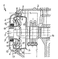
Die Figur zeigt eine Entlüftungsvorrichtung 1 für die Entlüftung
des Öl-Luft-Gemisches in einem Kurbelgehäuse 2 einer
Brennkraftmaschine. Die Entlüftungsvorrichtung 1 umfaßt einen
Zentrifugal-Ölabscheider 3, der drehfest mit einer Ausgleichswelle
14 verbunden ist und einen Abschlußdeckel 12 im
Wandbereich des Kurbelgehäuses 2 aufweist. Der Ölabscheider 3
dreht mit gleicher Drehzahl wie die Ausgleichswelle 14, der
Ölabscheider und die Ausgleichswelle haben eine gemeinsame
Drehachse 5.Further advantages and practical embodiments are the
further claims, the description of the figures and the drawing
can be seen in which an embodiment of the invention is shown
is.
The figure shows a
Es kann auch zweckmäßig sein, den Ölabscheider mit der Kurbelwelle oder der Nockenwelle zu verbinden bzw. über eine Steuerkette anzutreiben.It may also be appropriate to use the oil separator with the crankshaft or to connect the camshaft or via a To drive timing chain.
Der Ölabscheider 3 weist ein näherungsweise zylindrisches,
mehrteiliges Gehäuse 4 auf, das aus einem topfähnlichen
Grundkörper 15, einem ersten ringförmigen Aufbaukörper 16 und
einem zweiten ringförmigen Aufbaukörper 17 besteht, wobei der
erste Aufbaukörper 16 auf die Stirnseite der Gehäusewandung
des Grundkörpers 15 und in entsprechender Weise der zweite
Aufbaukörper 17 auf den ersten Aufbaukörper 16 aufgesetzt
ist. Der Grundkörper 15 und die beiden Aufbaukörper 16, 17
bilden eine Einheit und sind unverlierbar zusammengehalten.The
Im Gehäuse 4 des Ölabscheiders 3 ist eine etwa hülsenförmige
Trennwand 10 vorgesehen, die einteilig mit dem ersten Aufbaukörper
16 ausgebildet ist. Radial zwischen der Trennwand 10
und der radial außenliegenden Wandung des Gehäuses 4 ist ein
Einströmkanal 6 gebildet, der im wesentlichen parallel zur
Drehachse 5 und mit radialem Versatz zur Drehachse 5 verläuft,
wobei die Einströmöffnung des Einströmkanals 6 im Bereich
einer axialen, dem Abschlußdeckel 12 zugewandten Stirnseite
des Gehäuses 4 liegt. Der Einströmkanal 6 ist ringförmig
aufgebaut, entsprechend erstreckt sich die Einströmöffnung
an der axialen Stirnseite über 360° über den gesamten
Umfang. Gegebenenfalls können anstelle eines ringförmigen
Einströmkanals auch mehrere, über den Umfang segmentweise
verteilte Einströmkanäle angeordnet sein.In the
Zwischen der Außenwand 8 des Einströmkanals im Bereich des
ersten Aufbaukörpers 16 und der radial innenliegenden Trennwand
10 ist ein Durchlaß gebildet, über den der Einströmkanal
6 mit dem Innenraum des Gehäuses 4 kommuniziert.Between the
Der stationär am Kurbelgehäuse 2 befestigte Abschlußdeckel 12
weist eine ringförmige Aufnahmenut 18 auf, in der die freie
Stirnseite der Trennwand 10 aufgenommen ist. In der Aufnahmenut
18 ist ein Dichtring 19 angeordnet, um den Innenraum des
Ölabscheiders strömungsdicht gegen den Kurbelgehäuseinnenraum
abzuschließen und Fehlluftströme zu verhindern. Die Stirnseite
der Trennwand 10 ist drehbar in der Aufnahmenut 18 aufgenommen.
Im Abschlußdeckel 12 ist eine axiale Abströmöffnung 7
vorgesehen, über die der Gehäuseinnenraum mit dem Ansaugtrakt
der Brennkraftmaschine in Verbindung steht. Zwischen der dem
Kurbelgehäuseinnenraum zugewandten Innenseite des Abschlußdeckels
12 und dem Gehäuse 4 des Ölabscheiders 3 ist ein Zuführkanal
13 gebildet, über den das Öl-Luft-Gemisch aus dem
Kurbelgehäuseinnenraum in den Einströmkanal 6 geleitet wird.
Der Zuführkanal 13 lenkt das axial anströmende Öl-Luft-Gemisch
um 180° um und leitet das Gemisch in das Gehäuse 4.The
Der Zuführkanal ist nicht erforderlich, wenn die Einströmöffnung des Ölabscheiders auf der gegenüberliegenden, dem Abschlußdeckel abgewandten Seite angeordnet ist.The feed channel is not necessary when the inflow opening of the oil separator on the opposite end cover opposite side is arranged.
Im Einströmkanal 6 sind Schikanen 11 angeordnet, die in Form
von winklig verlaufenden Stegen in den freien Strömungsquerschnitt
des Einströmkanals 6 einragen. Es sind in Strömungsrichtung
mehrere hintereinander angeordnete Schikanen 11 vorgesehen,
die zweckmäßig abwechselnd von gegenüberliegenden
Seiten in den Einströmkanal einragen. Im Bereich der Einströmöffnung
ragt eine Schikane 11, die einteilig mit dem
zweiten Aufbaukörper 17 des Gehäuses 4 ausgebildet ist, in
den Einströmkanal 6 ein. Eine weitere Schikane 11 ist an der
Trennwand 10 befestigt. Das Öl-Luft-Gemisch wird gemäß den
eingezeichneten Strömungspfeilen mehrfach um 180° im Einströmkanal
6 um die Schikanen 11 umgelenkt.In the
In der Außenwand 8 des Einströmkanals 6 sind Abströmbohrungen
9 für abgeschiedenes Öl eingebracht, die zweckmäßig gleichmäßig
über den Umfang der Außenwand 8 verteilt sind, wobei
axial sowohl im Grundkörper 15 als auch im ersten Aufbaukörper
16 und gegebenenfalls auch im zweiten Aufbaukörper 17 Abströmbohrungen
9 vorgesehen sind. Anstelle von Abströmbohrungen
können auch Öffnungen mit beliebigem Querschnitt, beispielsweise
Spalte, vorgesehen sein. Aus konstruktiven Gründen
kann es auch vorteilhaft sein, die Abströmbohrungen über
den Umfang ungleichmäßig verteilt anzuordnen.In the
Die Ölabscheidung funktioniert wie folgt:
Das Öl-Luft-Gemisch aus dem Kurbelgehäuseinnenraum strömt in
Richtung der eingetragenen Strömungspfeile in den Zuführkanal
13 und weiter in den Einströmkanal 6, wobei das Gemisch durch
die Schikanen 11 geleitet wird und an den Wänden der Schikanen
bzw. an der Innenseite der Außenwand 8 abgeschieden wird.
Infolge der Rotationsbewegung des drehfest mit der Ausgleichswelle
14 verbundenen Gehäuses 4 wirken Zentrifugalkräfte
auf die Ölpartikel, so daß die Ölpartikel an die Innenseite
der Außenwand 8 gedrückt werden und über die Abströmbohrungen
9 radial nach außen zurück in den Kurbelgehäuseinnenraum
strömen. Die Strömung wird durch die Rotationsbewegung
nicht beeinträchtigt, so daß die von den Ölpartikel
befreite Reinluft in den Gehäuseinnenraum eintreten und
über die Abströmöffnung 7 den Ölabscheider 3 verlassen kann.The oil separation works as follows:
The oil-air mixture from the crankcase interior flows in the direction of the entered flow arrows into the
Claims (10)
- Ventilation device for a crankcase of an internal combustion engine, with a powered centrifugal oil separator (3) arranged in such a way that it can be rotated about a rotation axis (5) which has a case (4) with an inlet channel (6) for the supply of a mixture of oil and air and an outlet opening (7) for the removal of pure air, wherein the inlet channel (6) runs radially offset and essentially axis parallel to the rotation axis (5) of the oil separator (3)
characterised in that
a closure cover of the case (4) fixed on the crankcase (2) is provided and between the closure cover (12) and the case (4) a feed channel (13) is formed which is set away from the inlet channel (6) and communicates with the same. - Ventilation device according to claim 1
characterised in that
the outer wall (8) of the inlet channel (6) is part of the wall of the case (4). - Ventilation device according to claim 1 or 2
characterised in that
drainage bores (9) for oil running out are provided in the outer wall (8) of the inlet channel (6). - Ventilation device according to one of the claims 1 to 3
characterised in that
a dividing wall (10) is formed between the inlet channel (6) and the inner area of the oil separator (3). - Ventilation device according to one of the claims 1 to 4
characterised in that
the inlet channel (6) is annular. - Ventilation device according to one of the claims 1 to 5
characterised in that
baffles (11) for the oil separation are arranged in the inlet channel (6). - Ventilation device according to claim 6
characterised in that
the baffles (11) are formed as webs projecting at an angle into the inlet channel (6). - Ventilation device according to claim 6 or 7
characterised in that
at least two baffles (11) lying behind each other are arranged in the axial direction of the inlet channel (6). - Ventilation device according to one of the claims 1 to 8
characterised in that
the feed channel (13) is deflected by 180°. - Ventilation device according to one of the claims 1 to 9
characterised in that
the case (4) of the centrifugal oil separator (3) is connected in a rotationally secure way with a motorised compensating shaft (14).
Applications Claiming Priority (2)
| Application Number | Priority Date | Filing Date | Title |
|---|---|---|---|
| DE19803872 | 1998-01-31 | ||
| DE19803872A DE19803872C2 (en) | 1998-01-31 | 1998-01-31 | Ventilation device for a crankcase of an internal combustion engine |
Publications (2)
| Publication Number | Publication Date |
|---|---|
| EP0933507A1 EP0933507A1 (en) | 1999-08-04 |
| EP0933507B1 true EP0933507B1 (en) | 2002-09-25 |
Family
ID=7856305
Family Applications (1)
| Application Number | Title | Priority Date | Filing Date |
|---|---|---|---|
| EP98123975A Expired - Lifetime EP0933507B1 (en) | 1998-01-31 | 1998-12-17 | Device for crankcase ventilation for an internal combusion engine |
Country Status (3)
| Country | Link |
|---|---|
| US (1) | US5954035A (en) |
| EP (1) | EP0933507B1 (en) |
| DE (2) | DE19803872C2 (en) |
Cited By (2)
| Publication number | Priority date | Publication date | Assignee | Title |
|---|---|---|---|---|
| WO2006119890A1 (en) | 2005-05-09 | 2006-11-16 | Alfa Laval Tumba Ab | Apparatus for the purification of gas while bleeding a crank housing |
| CN107427846A (en) * | 2015-03-02 | 2017-12-01 | 东京滤器株式会社 | Oil eliminator |
Families Citing this family (44)
| Publication number | Priority date | Publication date | Assignee | Title |
|---|---|---|---|---|
| DE19909434C2 (en) * | 1999-03-04 | 2001-02-08 | Daimler Chrysler Ag | Device for separating oil from the blowby gases of an internal combustion engine |
| SE516944C2 (en) * | 1999-06-30 | 2002-03-26 | Volvo Lastvagnar Ab | Oil separator for small particles |
| DE19931740C2 (en) * | 1999-07-08 | 2001-06-13 | Daimler Chrysler Ag | Reciprocating internal combustion engine with a camshaft |
| DE19947143C1 (en) * | 1999-10-01 | 2001-04-05 | Daimler Chrysler Ag | IC motor crankcase air bleeding system has a centrifugal oil separator with a compensation weight and an oil separation zone linked to an axial flow channel for the cleaned air in a simple structure |
| FR2804477B1 (en) * | 2000-01-28 | 2002-04-12 | Renault Vehicules Ind | DEVICE FOR EXHAUSTING GAS FROM THE HOUSING OF AN INTERNAL COMBUSTION ENGINE |
| DE10026341B4 (en) * | 2000-05-26 | 2006-12-14 | Daimlerchrysler Ag | Centrifugal separation for crankcase ventilation |
| US6758197B2 (en) * | 2000-09-01 | 2004-07-06 | Bombardier-Rotax Gmbh | Blow-by gas separator and decompressor for an internal combustion engine |
| WO2002018820A1 (en) * | 2000-09-01 | 2002-03-07 | Bombardier-Rotax Gmbh | Continuously variable transmission for an internal combustion engine |
| DE10044615A1 (en) * | 2000-09-09 | 2002-04-04 | Mahle Filtersysteme Gmbh | Ventilation device for a crankcase |
| JP3923288B2 (en) * | 2001-08-06 | 2007-05-30 | 本田技研工業株式会社 | Engine gas-liquid separator |
| US6640792B2 (en) | 2001-08-16 | 2003-11-04 | Commins Engine Company, Inc. | Air/oil coalescer with an improved centrifugally assisted drainage |
| DE10205981B4 (en) * | 2002-02-14 | 2014-01-09 | Mann + Hummel Gmbh | Switchable cyclones for separating particles or drops from a fluid stream |
| DE10226695A1 (en) * | 2002-06-15 | 2003-12-24 | Daimler Chrysler Ag | Centrifugal oil separator in a crankcase of an internal combustion engine |
| SE522473C2 (en) * | 2002-06-20 | 2004-02-10 | Alfa Laval Corp Ab | A method and apparatus for purifying crankcase gas |
| SE0201982D0 (en) * | 2002-06-24 | 2002-06-24 | Alfa Laval Corp Ab | Ways to clean crankcase gas and a gas purifier separator |
| US6584964B1 (en) * | 2002-08-13 | 2003-07-01 | Briggs & Stratton Corporation | Engine having a centrifugal oil separator |
| DE20302824U1 (en) * | 2003-02-21 | 2004-07-08 | Hengst Gmbh & Co.Kg | Oil separator for cleaning crankcase ventilation gas of an internal combustion engine containing oil mist |
| US7235177B2 (en) | 2003-04-23 | 2007-06-26 | Fleetguard, Inc. | Integral air/oil coalescer for a centrifuge |
| EP1718858A4 (en) * | 2004-01-28 | 2010-09-15 | New Condensator Inc | Apparatus for removing contaminants from crankcase emissions |
| US7428898B2 (en) * | 2004-01-28 | 2008-09-30 | New Condensator, Inc. | Apparatus for removing contaminants from crankcase emissions |
| US6925993B1 (en) * | 2004-04-15 | 2005-08-09 | Alfa Laval Corporate Ab | Apparatus for cleaning of crankcase gas |
| AT501031B1 (en) * | 2004-09-02 | 2006-11-15 | Avl List Gmbh | INTERNAL COMBUSTION ENGINE WITH AT LEAST ONE CAMSHAFT AT LEAST ONE VENTILATION DUCT |
| SE527877C2 (en) * | 2004-11-29 | 2006-07-04 | Alfa Laval Corp Ab | Device for purification of crankcase gases |
| EP1880085B2 (en) * | 2005-05-10 | 2013-10-09 | Mahle International GmbH | Centrifugal oil mist separation device integrated in an axial hollow shaft of an internal combustion engine |
| US7455057B2 (en) * | 2005-11-14 | 2008-11-25 | Brp-Rotax Gmbh & Co. Kg | Internal combustion engine blow-by gas ventilation system |
| DE102005061256A1 (en) * | 2005-12-20 | 2007-06-21 | Günter Dr. Slowik | Method and device for deoiling crankcase ventilation gases of an internal combustion engine |
| US7338546B2 (en) * | 2006-04-19 | 2008-03-04 | Alfa Laval Corporate Ab | Centrifugal separator for cleaning gas generated by an internal combustion engine and a method for operating the same |
| US7438065B2 (en) * | 2006-08-16 | 2008-10-21 | Fuji Jukogyo Kabushiki Kaisha | Breather device in engine |
| FR2913061B1 (en) * | 2007-02-27 | 2009-05-22 | Snecma Sa | SHEATHING SYSTEM FOR AN AIRCRAFT ENGINE. |
| US8075655B2 (en) * | 2008-06-17 | 2011-12-13 | Cummins Filtration Ip, Inc. | Rotative inertial impactor gas-oil separator for internal combustion engine |
| WO2011084161A2 (en) * | 2010-01-08 | 2011-07-14 | Husqvarna Forestry Products N.A. Inc. | Mechanical breather system for a four-stroke engine |
| SE534773C2 (en) * | 2010-04-09 | 2011-12-13 | Alfa Laval Corp Ab | Centrifugal separator located inside an internal combustion engine |
| DE102011000458A1 (en) | 2011-02-02 | 2012-08-02 | Thyssenkrupp Presta Teccenter Ag | Shaft, in particular camshaft with a hollow shaft section |
| US8844506B2 (en) * | 2012-05-17 | 2014-09-30 | GM Global Technology Operations LLC | Positive crankcase ventilation system |
| CN102661184B (en) * | 2012-05-21 | 2014-12-17 | 隆鑫通用动力股份有限公司 | Forced centrifugal fine filter and engine of forced centrifugal fine filter |
| EP2826965B1 (en) * | 2013-07-15 | 2020-11-04 | Caterpillar Energy Solutions GmbH | Removing of blow-by gas out of crankcase without auxiliary drive |
| CN104612781A (en) * | 2014-11-21 | 2015-05-13 | 重庆隆鑫发动机有限公司 | Centrifugal engine oil fine filter and engine thereof |
| DE102015205557B4 (en) * | 2015-03-26 | 2017-05-24 | Mtu Friedrichshafen Gmbh | Internal combustion engine and method for operating an internal combustion engine |
| EP3112034A1 (en) | 2015-07-03 | 2017-01-04 | Alfa Laval Corporate AB | Centrifugal separator structure and assembly |
| DE102016008299B4 (en) * | 2016-07-06 | 2020-12-31 | Neander Motors Ag | Oil separator for an internal combustion engine |
| FR3064672B1 (en) * | 2017-03-28 | 2021-03-05 | Sogefi Filtration Spa | ROTATING DEVICE FOR SEPARATING THE OIL FROM THE CRANKCASE GASES OF AN INTERNAL COMBUSTION ENGINE |
| US10344983B2 (en) * | 2017-06-20 | 2019-07-09 | Pratt & Whitney Canada Corp. | Assembly of tube and structure crossing multi chambers |
| CN109322747B (en) * | 2018-12-14 | 2024-02-02 | 哈尔滨广瀚动力技术发展有限公司 | Static air separator of gas turbine lubricating oil system |
| DE102020205602B4 (en) * | 2020-05-04 | 2023-06-01 | Volkswagen Aktiengesellschaft | Torsional vibration damper and internal combustion engine with torsional vibration damper and oil separator |
Family Cites Families (13)
| Publication number | Priority date | Publication date | Assignee | Title |
|---|---|---|---|---|
| DE966346C (en) * | 1945-02-27 | 1957-07-25 | Daimler Benz Ag | Oil slingshot, especially for the oil circuit of aircraft engines |
| DE1097755B (en) * | 1958-05-17 | 1961-01-19 | Daimler Benz Ag | Device for venting internal combustion engines |
| FR1590886A (en) * | 1968-11-06 | 1970-04-20 | ||
| US3834156A (en) * | 1973-01-10 | 1974-09-10 | Wallace Murray Corp | Engine turbocharging system with vented compressor bearing |
| JPS585044Y2 (en) * | 1979-04-16 | 1983-01-28 | 日産自動車株式会社 | Oil separator for blow-by gas circulation device of internal combustion engine |
| JPS61175213A (en) * | 1985-01-30 | 1986-08-06 | Honda Motor Co Ltd | Breather device in cam casing in engine |
| US5114446A (en) * | 1991-02-15 | 1992-05-19 | United Technologies Corporation | Deoiler for jet engine |
| US5239972A (en) * | 1992-03-24 | 1993-08-31 | Nippon Soken, Inc. | Gas/liquid separation device |
| JPH07150924A (en) * | 1993-12-01 | 1995-06-13 | Nissan Motor Co Ltd | Oil separator for blow-by gas |
| US5507268A (en) * | 1994-09-08 | 1996-04-16 | Schlattl; Alice | Device for removing oil and/or soot from a stream of air, gas and or vapor, particularly for use in combustion engines |
| AT403508B (en) * | 1995-12-22 | 1998-03-25 | Bombardier Rotax Gmbh | CRANKSHAFT DRIVE WITH A COMBUSTION ENGINE |
| DE19607919B4 (en) * | 1996-03-01 | 2005-03-17 | Bayerische Motoren Werke Ag | Centrifugal oil separator for the blow-by gases of an internal combustion engine |
| DE19704845A1 (en) * | 1997-02-08 | 1998-08-13 | Bmw Rolls Royce Gmbh | Aircraft power plant oil separator |
-
1998
- 1998-01-31 DE DE19803872A patent/DE19803872C2/en not_active Expired - Fee Related
- 1998-12-17 DE DE59805683T patent/DE59805683D1/en not_active Expired - Lifetime
- 1998-12-17 EP EP98123975A patent/EP0933507B1/en not_active Expired - Lifetime
-
1999
- 1999-01-25 US US09/236,447 patent/US5954035A/en not_active Expired - Lifetime
Cited By (5)
| Publication number | Priority date | Publication date | Assignee | Title |
|---|---|---|---|---|
| WO2006119890A1 (en) | 2005-05-09 | 2006-11-16 | Alfa Laval Tumba Ab | Apparatus for the purification of gas while bleeding a crank housing |
| DE102005021278B4 (en) * | 2005-05-09 | 2010-04-15 | Alfa Laval Tumba Ab | Device for cleaning gas when venting a crankcase |
| US8172917B2 (en) | 2005-05-09 | 2012-05-08 | Alfa Laval Tumba Ab | Apparatus for the purification of gas while bleeding a crank housing |
| CN107427846A (en) * | 2015-03-02 | 2017-12-01 | 东京滤器株式会社 | Oil eliminator |
| CN107427846B (en) * | 2015-03-02 | 2019-11-22 | 东京滤器株式会社 | Oil eliminator |
Also Published As
| Publication number | Publication date |
|---|---|
| DE19803872A1 (en) | 1999-08-05 |
| DE19803872C2 (en) | 2001-05-10 |
| EP0933507A1 (en) | 1999-08-04 |
| US5954035A (en) | 1999-09-21 |
| DE59805683D1 (en) | 2002-10-31 |
Similar Documents
| Publication | Publication Date | Title |
|---|---|---|
| EP0933507B1 (en) | Device for crankcase ventilation for an internal combusion engine | |
| DE10065328B4 (en) | Gas / liquid separator of the cyclone type | |
| DE102006038700B4 (en) | Device for separating liquids from gases | |
| EP1422389A2 (en) | Centrifugal oil separator | |
| EP2603674B1 (en) | Hollow body with integrated oil separator | |
| DE102006058980B4 (en) | Vane pump | |
| DE10235983A1 (en) | Air-oil separator for an engine | |
| EP2069042B1 (en) | Device for separating particles from a gas flow | |
| WO2003106821A1 (en) | Centrifugal oil separator for use in the crankcase of an internal combustion engine | |
| DE112019000506B4 (en) | FILTER DEVICE, PARTICULARLY FOR GAS FILTRATION | |
| DE102005034273A1 (en) | Combustion engine e.g. for motor vehicle, has two cam shafts in cylinder head with first cam shaft having longitudinal bore hole for conveying Blow-By-Gas and oil separating device provided | |
| DE19947143C1 (en) | IC motor crankcase air bleeding system has a centrifugal oil separator with a compensation weight and an oil separation zone linked to an axial flow channel for the cleaned air in a simple structure | |
| DE102004011177B4 (en) | Cylinder head cover with oil separator | |
| DE10140301A1 (en) | Crankcase venting device has separating wall perpendicular to axis of rotation as baffle | |
| DE19706383C2 (en) | Ventilation device for a crankcase of an internal combustion engine | |
| WO2019145133A1 (en) | Filter housing for a filter device | |
| WO2020064204A1 (en) | Air de-oiling insert for an air de-oiling device and air de-oiling device | |
| DE60035268T2 (en) | Centrifuge rotor with reaction drive | |
| EP3743191B1 (en) | Filter device comprising a filter element in a filter housing | |
| WO2019145132A1 (en) | Filter module comprising a filter element in a filter housing | |
| DE3240710C2 (en) | Exhaust silencer | |
| WO2020064205A1 (en) | Air de-oiling device for separating oil contained in air and air de-oiling insert for an air de-oiling device | |
| EP3743190B1 (en) | Filter element, in particular for gas filtration | |
| DE19909434C2 (en) | Device for separating oil from the blowby gases of an internal combustion engine | |
| DE10236332B4 (en) | Device for venting a crankcase |
Legal Events
| Date | Code | Title | Description |
|---|---|---|---|
| PUAI | Public reference made under article 153(3) epc to a published international application that has entered the european phase |
Free format text: ORIGINAL CODE: 0009012 |
|
| AK | Designated contracting states |
Kind code of ref document: A1 Designated state(s): DE FR GB IT |
|
| AX | Request for extension of the european patent |
Free format text: AL;LT;LV;MK;RO;SI |
|
| 17P | Request for examination filed |
Effective date: 19990703 |
|
| AKX | Designation fees paid |
Free format text: DE FR GB IT |
|
| 17Q | First examination report despatched |
Effective date: 20010612 |
|
| GRAG | Despatch of communication of intention to grant |
Free format text: ORIGINAL CODE: EPIDOS AGRA |
|
| GRAG | Despatch of communication of intention to grant |
Free format text: ORIGINAL CODE: EPIDOS AGRA |
|
| GRAH | Despatch of communication of intention to grant a patent |
Free format text: ORIGINAL CODE: EPIDOS IGRA |
|
| GRAH | Despatch of communication of intention to grant a patent |
Free format text: ORIGINAL CODE: EPIDOS IGRA |
|
| GRAA | (expected) grant |
Free format text: ORIGINAL CODE: 0009210 |
|
| AK | Designated contracting states |
Kind code of ref document: B1 Designated state(s): DE FR GB IT |
|
| REG | Reference to a national code |
Ref country code: GB Ref legal event code: FG4D Free format text: NOT ENGLISH |
|
| REF | Corresponds to: |
Ref document number: 59805683 Country of ref document: DE Date of ref document: 20021031 |
|
| GBT | Gb: translation of ep patent filed (gb section 77(6)(a)/1977) |
Effective date: 20021128 |
|
| ET | Fr: translation filed | ||
| PLBE | No opposition filed within time limit |
Free format text: ORIGINAL CODE: 0009261 |
|
| STAA | Information on the status of an ep patent application or granted ep patent |
Free format text: STATUS: NO OPPOSITION FILED WITHIN TIME LIMIT |
|
| 26N | No opposition filed |
Effective date: 20030626 |
|
| PGFP | Annual fee paid to national office [announced via postgrant information from national office to epo] |
Ref country code: GB Payment date: 20031126 Year of fee payment: 6 |
|
| PGFP | Annual fee paid to national office [announced via postgrant information from national office to epo] |
Ref country code: FR Payment date: 20031209 Year of fee payment: 6 |
|
| PG25 | Lapsed in a contracting state [announced via postgrant information from national office to epo] |
Ref country code: GB Free format text: LAPSE BECAUSE OF NON-PAYMENT OF DUE FEES Effective date: 20041217 |
|
| GBPC | Gb: european patent ceased through non-payment of renewal fee |
Effective date: 20041217 |
|
| PG25 | Lapsed in a contracting state [announced via postgrant information from national office to epo] |
Ref country code: FR Free format text: LAPSE BECAUSE OF NON-PAYMENT OF DUE FEES Effective date: 20050831 |
|
| REG | Reference to a national code |
Ref country code: FR Ref legal event code: ST |
|
| PG25 | Lapsed in a contracting state [announced via postgrant information from national office to epo] |
Ref country code: IT Free format text: LAPSE BECAUSE OF NON-PAYMENT OF DUE FEES Effective date: 20051217 |
|
| PGFP | Annual fee paid to national office [announced via postgrant information from national office to epo] |
Ref country code: DE Payment date: 20140228 Year of fee payment: 16 |
|
| REG | Reference to a national code |
Ref country code: DE Ref legal event code: R119 Ref document number: 59805683 Country of ref document: DE |
|
| PG25 | Lapsed in a contracting state [announced via postgrant information from national office to epo] |
Ref country code: DE Free format text: LAPSE BECAUSE OF NON-PAYMENT OF DUE FEES Effective date: 20150701 |