EP0933507B1 - Dispositif de ventilation de carter d'un moteur à combustion interne - Google Patents
Dispositif de ventilation de carter d'un moteur à combustion interne Download PDFInfo
- Publication number
- EP0933507B1 EP0933507B1 EP98123975A EP98123975A EP0933507B1 EP 0933507 B1 EP0933507 B1 EP 0933507B1 EP 98123975 A EP98123975 A EP 98123975A EP 98123975 A EP98123975 A EP 98123975A EP 0933507 B1 EP0933507 B1 EP 0933507B1
- Authority
- EP
- European Patent Office
- Prior art keywords
- oil
- ventilation device
- inlet channel
- wall
- oil separator
- Prior art date
- Legal status (The legal status is an assumption and is not a legal conclusion. Google has not performed a legal analysis and makes no representation as to the accuracy of the status listed.)
- Expired - Lifetime
Links
Images
Classifications
-
- F—MECHANICAL ENGINEERING; LIGHTING; HEATING; WEAPONS; BLASTING
- F01—MACHINES OR ENGINES IN GENERAL; ENGINE PLANTS IN GENERAL; STEAM ENGINES
- F01M—LUBRICATING OF MACHINES OR ENGINES IN GENERAL; LUBRICATING INTERNAL COMBUSTION ENGINES; CRANKCASE VENTILATING
- F01M13/00—Crankcase ventilating or breathing
- F01M13/04—Crankcase ventilating or breathing having means for purifying air before leaving crankcase, e.g. removing oil
- F01M2013/0422—Separating oil and gas with a centrifuge device
Definitions
- the invention relates to a ventilation device for a crankcase an internal combustion engine according to the preamble of Claim 1.
- a venting device is known from DE 196 07 919 A1, by means of which the oil particles in the oil-air mixture of a crankcase separated and returned to the oil pan.
- the venting device comprises a centrifugal oil separator with a rotating housing that is several radial has extending inflow channels, which in a central, axial running outflow channel open.
- the oil-air mixture will guided radially from the outside in through the inflow channels, in which obstacles are arranged, due to the by the rotational movement of the housing generated centrifugal forces the oil particles of the oil-air mixture are separated at the obstacles and against the inflow direction of the oil-air mixture are thrown radially outwards.
- the one from the Air freed from oil particles is discharged via the outflow channel and the intake tract of the internal combustion engine.
- This venting device has the disadvantage that on the one hand the oil-air mixture is fed radially from the outside inwards, on the other hand the separated oil particles radially in the opposite direction be dissipated from the inside out so that within the Inflow channel two opposing flows arise.
- This has one limited efficiency of the ventilation device, both in terms of flow rate and also with regard to the degree of cleaning, because the opposite Currents hinder each other and at least partially one permanent mixing of both streams takes place.
- one Increasing the speed of the centrifugal separator does not lead to anything better efficiency because with increasing rotation speed the outward oil particle flow the inward directional oil-air flow is increasingly entraining.
- the invention is based on the problem of efficiency Venting device with a centrifugal oil separator to improve with simple means.
- Another advantage is the axial entry of the oil-air mixture in the oil separator because the oil-air mixture before the Entry opening into the housing of the oil separator none or is subjected to low centrifugal forces and entry the flow into the housing is not hindered.
- a cover attached to the crankcase provided that additionally supports the oil separator and also the interior of the crankcase flow-tight against the atmosphere concludes.
- a feed channel is formed, which contains the oil-air mixture the inflow channel in the interior of the crankcase supplies.
- This feed channel preferably describes a deflection of about 180 °, so that already on the inner wall of the feed channel a pre-separation of oil particles from the supplied Oil-air mixture takes place.
- the outer wall of the inflow channel is expediently identical to a radial wall portion of the housing, the inflow opening of the inflow channel on an end face of the housing lies.
- This version is characterized by a simple design with no specially designed outer wall is required for the inflow channel.
- In the outer wall are advantageous Outflow holes introduced through which the separated Oil can drain off.
- the inflow channel is preferably designed annularly around the Entry of the oil-air mixture into the housing over the entire To enable the scope of the housing. In this rotationally symmetrical Training can achieve the greatest possible throughput become.
- the partition can on the End cover be rotatably mounted.
- the baffles suitably arranged in the inflow channel can formed as webs projecting at an angle into the inflow channel be, in particular at least two consecutive Baffles are provided, which alternate, for example the outer wall and can be arranged on the partition, so that the inflowing mixture is redirected at least once and oil can deposit on the surfaces of the webs.
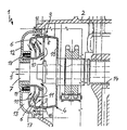
- the figure shows a ventilation device 1 for ventilation of the oil-air mixture in a crankcase 2 one Internal combustion engine.
- the venting device 1 comprises one Centrifugal oil separator 3, which rotates with a balance shaft 14 is connected and a cover 12 in Has wall area of the crankcase 2.
- the oil separator 3 rotates at the same speed as the balancer shaft 14, the Oil separator and the balance shaft have a common Axis of rotation 5.
- the oil separator 3 has an approximately cylindrical, multi-part housing 4, which consists of a pot-like Base body 15, a first annular body 16 and a second annular body 17, the first body 16 on the end face of the housing wall of the base body 15 and the second in a corresponding manner Body 17 placed on the first body 16 is.
- the base body 15 and the two body parts 16, 17 form a unit and are held together captively.
- an approximately sleeve-shaped Partition 10 is provided, which is in one piece with the first body 16 is formed.
- a Inflow channel 6 is formed, which is substantially parallel to Axis of rotation 5 and with a radial offset to the axis of rotation 5, the inflow opening of the inflow channel 6 in the region an axial end face facing the end cover 12 of the housing 4 is.
- the inflow channel 6 is annular constructed, the inflow opening extends accordingly on the axial face over 360 ° over the entire Scope. If necessary, instead of an annular Inflow channel also several, segment-wise over the circumference Distributed inflow channels can be arranged.
- the cover plate 12 fixed to the crankcase 2 has an annular receiving groove 18 in which the free End face of the partition 10 is added.
- a sealing ring 19 is arranged to the interior of the Oil separator flow-tight against the crankcase interior to complete and prevent incorrect air flows.
- the face the partition 10 is rotatably received in the receiving groove 18.
- In the end cover 12 there is an axial outflow opening 7 provided, through which the housing interior with the intake tract the internal combustion engine is connected.
- a feed channel 13 formed over which the oil-air mixture from the Crankcase interior is passed into the inflow channel 6.
- the feed channel 13 directs the axially flowing oil-air mixture by 180 ° and directs the mixture into the housing 4.
- the feed channel is not necessary when the inflow opening of the oil separator on the opposite end cover opposite side is arranged.
- baffles 11 are arranged, which are in shape of angled webs into the free flow cross section of the inflow channel 6 protrude. They are in the direction of flow several baffles 11 arranged one behind the other are provided, which expediently alternate from opposite Insert sides into the inflow channel.
- a chicane 11 which is integral with the second body 17 of the housing 4 is formed in the inflow channel 6.
- Another chicane 11 is on the Partition 10 attached.
- the oil-air mixture is according to the drawn flow arrows several times by 180 ° in the inflow channel 6 deflected around the baffles 11.
- outflow bores 9 introduced for separated oil, which is expediently even are distributed over the circumference of the outer wall 8, wherein axially both in the base body 15 and in the first body 16 and optionally also in the second body 17 outflow bores 9 are provided.
- drain holes can also have openings of any cross-section, for example Column.
- the outflow bores arrange the circumference unevenly.
- the oil separation works as follows: The oil-air mixture from the crankcase interior flows in the direction of the entered flow arrows into the feed channel 13 and further into the inflow channel 6, the mixture being passed through the baffles 11 and separated on the walls of the baffles or on the inside of the outer wall 8 becomes.
- centrifugal forces act on the oil particles, so that the oil particles are pressed against the inside of the outer wall 8 and flow radially outward through the outflow bores 9 back into the crankcase interior.
- the flow is not impaired by the rotational movement, so that the clean air freed from the oil particles can enter the interior of the housing and leave the oil separator 3 via the outflow opening 7.
Claims (10)
- Dispositif de mise à l'air pour un carter de vilebrequin d'un moteur à combustion interne, comportant un séparateur d'huile centrifuge (3) susceptible d'être entraíné et monté mobile en rotation autour d'un axe de rotation (5), qui comprend un carter (4) avec un canal d'entrée (6) pour l'alimentation d'un mélange huile-air et une ouverture d'évacuation (7) pour l'évacuation de l'air purifié, dans lequel le canal d'entrée (6) s'étend avec un décalage radial et dont l'axe s'étend sensiblement parallèlement à l'axe de rotation (5) du séparateur d'huile (3), caractérisé en ce qu'il est prévu un couvercle de fermeture (12) du carter (4), fixé sur le carter de vilebrequin (2), et en ce qu'il est prévu entre le couvercle de fermeture (12) et le carter (4) un canal d'alimentation (13) agencé en amont du canal d'entrée (6) et communiquant avec celui-ci.
- Dispositif de mise à l'air selon la revendication 1, caractérisé en ce que la paroi extérieure (8) du canal d'entrée (6) fait partie de la paroi du carter (4).
- Dispositif de mise à l'air selon l'une ou l'autre des revendications 1 et 2, caractérisé en ce qu'il est prévu des perçages d'évacuation (9) pour l'huile évacuée dans la paroi extérieure (8) du canal d'entrée (6).
- Dispositif de mise à l'air selon l'une des revendications 1 à 3, caractérisé en ce qu'une paroi de séparation (10) est réalisée entre le canal d'entrée (6) et le volume intérieur du séparateur d'huile (3).
- Dispositif de mise à l'air selon l'une des revendications 1 à 4, caractérisé en ce que le canal d'entrée (6) est réalisé sous forme annulaire.
- Dispositif de mise à l'air selon l'une des revendications 1 à 5, caractérisé en ce que des chicanes (11) pour la séparation d'huile sont agencées dans le canal d'entrée (6).
- Dispositif de mise à l'air selon la revendication 6, caractérisé en ce que les chicanes (11) sont réalisées sous forme de barrettes pénétrant sous un angle dans le canal d'entrée (6).
- Dispositif de mise à l'air selon l'une ou l'autre des revendications 6 et 7, caractérisé en ce qu'au moins deux chicanes (11) situées l'une derrière l'autre sont agencées en direction axiale du canal d'entrée (6).
- Dispositif de mise à l'air selon l'une des revendications 1 à 8, caractérisé en ce que le canal d'alimentation (13) subit un renvoi de 180°.
- Dispositif de mise à l'air selon l'une des revendications 1 à 9, caractérisé en ce que le carter (4) du séparateur d'huile centrifuge (3) est relié solidairement en rotation à un arbre d'équilibrage du moteur (14).
Applications Claiming Priority (2)
| Application Number | Priority Date | Filing Date | Title |
|---|---|---|---|
| DE19803872A DE19803872C2 (de) | 1998-01-31 | 1998-01-31 | Entlüfungsvorrichtung für ein Kurbelgehäuse einer Brennkraftmaschine |
| DE19803872 | 1998-01-31 |
Publications (2)
| Publication Number | Publication Date |
|---|---|
| EP0933507A1 EP0933507A1 (fr) | 1999-08-04 |
| EP0933507B1 true EP0933507B1 (fr) | 2002-09-25 |
Family
ID=7856305
Family Applications (1)
| Application Number | Title | Priority Date | Filing Date |
|---|---|---|---|
| EP98123975A Expired - Lifetime EP0933507B1 (fr) | 1998-01-31 | 1998-12-17 | Dispositif de ventilation de carter d'un moteur à combustion interne |
Country Status (3)
| Country | Link |
|---|---|
| US (1) | US5954035A (fr) |
| EP (1) | EP0933507B1 (fr) |
| DE (2) | DE19803872C2 (fr) |
Cited By (2)
| Publication number | Priority date | Publication date | Assignee | Title |
|---|---|---|---|---|
| WO2006119890A1 (fr) | 2005-05-09 | 2006-11-16 | Alfa Laval Tumba Ab | Dispositif pour purifier un gaz lors de l'evacuation de l'air contenu dans un carter de vilebrequin |
| CN107427846A (zh) * | 2015-03-02 | 2017-12-01 | 东京滤器株式会社 | 油分离器 |
Families Citing this family (44)
| Publication number | Priority date | Publication date | Assignee | Title |
|---|---|---|---|---|
| DE19909434C2 (de) * | 1999-03-04 | 2001-02-08 | Daimler Chrysler Ag | Vorrichtung zum Abscheiden von Öl aus den Blowby-Gasen einer Brennkraftmaschine |
| SE516944C2 (sv) * | 1999-06-30 | 2002-03-26 | Volvo Lastvagnar Ab | Oljeavskiljare för små partiklar |
| DE19931740C2 (de) * | 1999-07-08 | 2001-06-13 | Daimler Chrysler Ag | Hubkolbenbrennkraftmaschine mit einer Nockenwelle |
| DE19947143C1 (de) * | 1999-10-01 | 2001-04-05 | Daimler Chrysler Ag | Entlüftungsvorrichtung für ein Kurbelgehäuse einer Brennkraftmaschine |
| FR2804477B1 (fr) * | 2000-01-28 | 2002-04-12 | Renault Vehicules Ind | Dispositif d'evacuation des gaz du carter d'un moteur a combustion interne |
| DE10026341B4 (de) * | 2000-05-26 | 2006-12-14 | Daimlerchrysler Ag | Zentrifugalabscheidung zur Kurbelgehäuse-Entlüftung |
| US6758197B2 (en) * | 2000-09-01 | 2004-07-06 | Bombardier-Rotax Gmbh | Blow-by gas separator and decompressor for an internal combustion engine |
| CA2434861A1 (fr) * | 2000-09-01 | 2002-03-07 | Norbert Korenjak | Transmission a variations ininterrompues de vitesses pour moteur a combustion interne |
| DE10044615A1 (de) * | 2000-09-09 | 2002-04-04 | Mahle Filtersysteme Gmbh | Entlüftungsvorrichtung für ein Kurbelgehäuse |
| JP3923288B2 (ja) * | 2001-08-06 | 2007-05-30 | 本田技研工業株式会社 | エンジンの気液分離装置 |
| US6640792B2 (en) | 2001-08-16 | 2003-11-04 | Commins Engine Company, Inc. | Air/oil coalescer with an improved centrifugally assisted drainage |
| DE10205981B4 (de) | 2002-02-14 | 2014-01-09 | Mann + Hummel Gmbh | Schaltbare Zyklone zum Abscheiden von Partikeln oder Tropfen aus einem Fluidstrom |
| DE10226695A1 (de) * | 2002-06-15 | 2003-12-24 | Daimler Chrysler Ag | Zentrifugal-Ölabscheider in einem Kurbelgehäuse einer Brennkraftmaschine |
| SE522473C2 (sv) * | 2002-06-20 | 2004-02-10 | Alfa Laval Corp Ab | Ett sätt och en anordning för rening av vevhusgas |
| SE0201982D0 (sv) * | 2002-06-24 | 2002-06-24 | Alfa Laval Corp Ab | Sätt att rena vevhusgas samt en gasreningsseparator |
| US6584964B1 (en) * | 2002-08-13 | 2003-07-01 | Briggs & Stratton Corporation | Engine having a centrifugal oil separator |
| DE20302824U1 (de) * | 2003-02-21 | 2004-07-08 | Hengst Gmbh & Co.Kg | Ölabscheider für die Reinigung von Ölnebel enthaltendem Kurbelgehäuseentlüftungsgas einer Brennkraftmaschine |
| US7235177B2 (en) | 2003-04-23 | 2007-06-26 | Fleetguard, Inc. | Integral air/oil coalescer for a centrifuge |
| US7428898B2 (en) * | 2004-01-28 | 2008-09-30 | New Condensator, Inc. | Apparatus for removing contaminants from crankcase emissions |
| MXPA06007493A (es) * | 2004-01-28 | 2007-04-17 | New Condensator Inc | Aparato para remover contaminantes de emisiones del carter. |
| US6925993B1 (en) * | 2004-04-15 | 2005-08-09 | Alfa Laval Corporate Ab | Apparatus for cleaning of crankcase gas |
| AT501031B1 (de) * | 2004-09-02 | 2006-11-15 | Avl List Gmbh | Brennkraftmaschine mit zumindest einer mindestens einen entlüftungskanal aufweisenden nockenwelle |
| SE527877C2 (sv) * | 2004-11-29 | 2006-07-04 | Alfa Laval Corp Ab | Anordning för rening av vevhusgaser |
| JP5124448B2 (ja) * | 2005-05-10 | 2013-01-23 | マーレ インターナショナル ゲゼルシャフト ミット ベシュレンクテル ハフツング | 内燃機関の軸方向の中空軸内に組み込まれた遠心式のオイルミストセパレータ |
| US7455057B2 (en) * | 2005-11-14 | 2008-11-25 | Brp-Rotax Gmbh & Co. Kg | Internal combustion engine blow-by gas ventilation system |
| DE102005061256A1 (de) * | 2005-12-20 | 2007-06-21 | Günter Dr. Slowik | Verfahren und Vorrichtung zur Entölung von Kurbelgehäuseentlüftungsgasen einer Brennkraftmaschine |
| US7338546B2 (en) * | 2006-04-19 | 2008-03-04 | Alfa Laval Corporate Ab | Centrifugal separator for cleaning gas generated by an internal combustion engine and a method for operating the same |
| US7438065B2 (en) * | 2006-08-16 | 2008-10-21 | Fuji Jukogyo Kabushiki Kaisha | Breather device in engine |
| FR2913061B1 (fr) * | 2007-02-27 | 2009-05-22 | Snecma Sa | Systeme de deshuilage pour moteur d'aeronef. |
| US8075655B2 (en) * | 2008-06-17 | 2011-12-13 | Cummins Filtration Ip, Inc. | Rotative inertial impactor gas-oil separator for internal combustion engine |
| WO2011084161A2 (fr) * | 2010-01-08 | 2011-07-14 | Husqvarna Forestry Products N.A. Inc. | Système de reniflard mécanique pour un moteur à quatre temps |
| SE534773C2 (sv) * | 2010-04-09 | 2011-12-13 | Alfa Laval Corp Ab | Centrifugalseparator anordnad inuti en förbränningsmotor |
| DE102011000458A1 (de) | 2011-02-02 | 2012-08-02 | Thyssenkrupp Presta Teccenter Ag | Welle, insbesondere Nockenwelle mit einem hohlen Wellenabschnitt |
| US8844506B2 (en) * | 2012-05-17 | 2014-09-30 | GM Global Technology Operations LLC | Positive crankcase ventilation system |
| CN102661184B (zh) * | 2012-05-21 | 2014-12-17 | 隆鑫通用动力股份有限公司 | 强制离心式精滤器及其发动机 |
| EP2826965B1 (fr) * | 2013-07-15 | 2020-11-04 | Caterpillar Energy Solutions GmbH | Élimination de gaz de fuite hors du carter de vilebrequin sans entraînement auxiliaire |
| CN104612781A (zh) * | 2014-11-21 | 2015-05-13 | 重庆隆鑫发动机有限公司 | 机油离心式精滤器及其发动机 |
| DE102015205557B4 (de) * | 2015-03-26 | 2017-05-24 | Mtu Friedrichshafen Gmbh | Brennkraftmaschine und Verfahren zum Betreiben einer Brennkraftmaschine |
| EP3112034A1 (fr) | 2015-07-03 | 2017-01-04 | Alfa Laval Corporate AB | Structure et ensemble séparateur centrifuge |
| DE102016008299B4 (de) * | 2016-07-06 | 2020-12-31 | Neander Motors Ag | Ölabscheideeinrichtung für eine Brennkraftmaschine |
| FR3064672B1 (fr) * | 2017-03-28 | 2021-03-05 | Sogefi Filtration Spa | Dispositif tournant pour separer l'huile des gaz de carter d'un moteur a combustion interne |
| US10344983B2 (en) * | 2017-06-20 | 2019-07-09 | Pratt & Whitney Canada Corp. | Assembly of tube and structure crossing multi chambers |
| CN109322747B (zh) * | 2018-12-14 | 2024-02-02 | 哈尔滨广瀚动力技术发展有限公司 | 一种燃气轮机滑油系统静态空气分离器 |
| DE102020205602B4 (de) * | 2020-05-04 | 2023-06-01 | Volkswagen Aktiengesellschaft | Torsionsschwingungsdämpfer sowie Brennkraftmaschine mit Torsionsschwingungsdämpfer und Ölabscheider |
Family Cites Families (13)
| Publication number | Priority date | Publication date | Assignee | Title |
|---|---|---|---|---|
| DE966346C (de) * | 1945-02-27 | 1957-07-25 | Daimler Benz Ag | OElschleuder, insbesondere fuer den OElkreislauf von Flugmotoren |
| DE1097755B (de) * | 1958-05-17 | 1961-01-19 | Daimler Benz Ag | Vorrichtung zur Entlueftung von Brennkraftmaschinen |
| FR1590886A (fr) * | 1968-11-06 | 1970-04-20 | ||
| US3834156A (en) * | 1973-01-10 | 1974-09-10 | Wallace Murray Corp | Engine turbocharging system with vented compressor bearing |
| JPS585044Y2 (ja) * | 1979-04-16 | 1983-01-28 | 日産自動車株式会社 | 内燃機関のブロ−バイガス環元装置用オイルセパレ−タ |
| JPS61175213A (ja) * | 1985-01-30 | 1986-08-06 | Honda Motor Co Ltd | エンジンにおけるカムケ−スのブリ−ザ装置 |
| US5114446A (en) * | 1991-02-15 | 1992-05-19 | United Technologies Corporation | Deoiler for jet engine |
| US5239972A (en) * | 1992-03-24 | 1993-08-31 | Nippon Soken, Inc. | Gas/liquid separation device |
| JPH07150924A (ja) * | 1993-12-01 | 1995-06-13 | Nissan Motor Co Ltd | ブローバイガスのオイル分離器 |
| US5507268A (en) * | 1994-09-08 | 1996-04-16 | Schlattl; Alice | Device for removing oil and/or soot from a stream of air, gas and or vapor, particularly for use in combustion engines |
| AT403508B (de) * | 1995-12-22 | 1998-03-25 | Bombardier Rotax Gmbh | Kurbelwellenantrieb mit einem verbrennungsmotor |
| DE19607919B4 (de) * | 1996-03-01 | 2005-03-17 | Bayerische Motoren Werke Ag | Zentrifugal-Ölabscheider für die blow-by-Gase einer Brennkraftmaschine |
| DE19704845A1 (de) * | 1997-02-08 | 1998-08-13 | Bmw Rolls Royce Gmbh | Ölabscheider für ein Getriebe eines Flug-Triebwerkes |
-
1998
- 1998-01-31 DE DE19803872A patent/DE19803872C2/de not_active Expired - Fee Related
- 1998-12-17 DE DE59805683T patent/DE59805683D1/de not_active Expired - Lifetime
- 1998-12-17 EP EP98123975A patent/EP0933507B1/fr not_active Expired - Lifetime
-
1999
- 1999-01-25 US US09/236,447 patent/US5954035A/en not_active Expired - Lifetime
Cited By (5)
| Publication number | Priority date | Publication date | Assignee | Title |
|---|---|---|---|---|
| WO2006119890A1 (fr) | 2005-05-09 | 2006-11-16 | Alfa Laval Tumba Ab | Dispositif pour purifier un gaz lors de l'evacuation de l'air contenu dans un carter de vilebrequin |
| DE102005021278B4 (de) * | 2005-05-09 | 2010-04-15 | Alfa Laval Tumba Ab | Vorrichtung zum Reinigen von Gas beim Entlüften eines Kurbelgehäuses |
| US8172917B2 (en) | 2005-05-09 | 2012-05-08 | Alfa Laval Tumba Ab | Apparatus for the purification of gas while bleeding a crank housing |
| CN107427846A (zh) * | 2015-03-02 | 2017-12-01 | 东京滤器株式会社 | 油分离器 |
| CN107427846B (zh) * | 2015-03-02 | 2019-11-22 | 东京滤器株式会社 | 油分离器 |
Also Published As
| Publication number | Publication date |
|---|---|
| US5954035A (en) | 1999-09-21 |
| DE19803872C2 (de) | 2001-05-10 |
| EP0933507A1 (fr) | 1999-08-04 |
| DE19803872A1 (de) | 1999-08-05 |
| DE59805683D1 (de) | 2002-10-31 |
Similar Documents
| Publication | Publication Date | Title |
|---|---|---|
| EP0933507B1 (fr) | Dispositif de ventilation de carter d'un moteur à combustion interne | |
| DE10065328B4 (de) | Gas-/Flüssigkeits-Abscheider der Zyklonart | |
| DE102006038700B4 (de) | Vorrichtung zur Abscheidung von Flüssigkeiten aus Gasen | |
| EP1422389A2 (fr) | Separateur d'huile centrifuge | |
| EP2603674B1 (fr) | CORPS CREUX À SEPARATEUR D'HuILE INTÉGRÉ | |
| DE102006058980B4 (de) | Flügelzellenpumpe | |
| DE10235983A1 (de) | Luft-Öl-Abscheidevorrichtung für einen Motor | |
| EP2069042B1 (fr) | Dispositif de séparation de particules d'un courant de gaz | |
| WO2003106821A1 (fr) | Separateur d'huile centrifuge utilise dans un carter de vilebrequin d'un moteur a combustion interne | |
| DE112019000506B4 (de) | Filtereinrichtung, insbesondere zur gasfiltration | |
| DE102005034273A1 (de) | Brennkraftmaschine | |
| DE19947143C1 (de) | Entlüftungsvorrichtung für ein Kurbelgehäuse einer Brennkraftmaschine | |
| DE102004011177B4 (de) | Zylinderkopfhaube mit Ölabscheider | |
| DE10140301A1 (de) | Entlüftungsvorrichtung für ein Kurbelgehäuse einer Brennkraftmaschine | |
| DE19706383C2 (de) | Entlüftungsvorrichtung für ein Kurbelgehäuse einer Brennkraftmaschine | |
| WO2019145133A1 (fr) | Boîtier de filtre pour dispositif de filtration | |
| WO2020064204A1 (fr) | Insert de déshuilage d'air d'un dispositif de déshuilage d'air et dispositif de déshuilage d'air | |
| DE60035268T2 (de) | Zentrifugenrotor mit Reaktionsantrieb | |
| EP3743191B1 (fr) | Dispositif de filtration comprenant un élément filtrant dans un boîtier de filtre | |
| WO2019145132A1 (fr) | Dispositif de filtration comprenant un élément filtrant dans un boîtier de filtre | |
| DE3240710C2 (de) | Entlüftungsschalldämpfer | |
| WO2020064205A1 (fr) | Dispositif de déshuilage d'air pour séparer l'huile contenue dans de l'air et insert de déshuilage d'air d'un dispositif de déshuilage d'air | |
| EP3743190B1 (fr) | Élément filtrant, en particulier pour la filtration de gaz | |
| DE19909434C2 (de) | Vorrichtung zum Abscheiden von Öl aus den Blowby-Gasen einer Brennkraftmaschine | |
| DE10236332B4 (de) | Einrichtung zum Entlüften eines Kurbelgehäuses |
Legal Events
| Date | Code | Title | Description |
|---|---|---|---|
| PUAI | Public reference made under article 153(3) epc to a published international application that has entered the european phase |
Free format text: ORIGINAL CODE: 0009012 |
|
| AK | Designated contracting states |
Kind code of ref document: A1 Designated state(s): DE FR GB IT |
|
| AX | Request for extension of the european patent |
Free format text: AL;LT;LV;MK;RO;SI |
|
| 17P | Request for examination filed |
Effective date: 19990703 |
|
| AKX | Designation fees paid |
Free format text: DE FR GB IT |
|
| 17Q | First examination report despatched |
Effective date: 20010612 |
|
| GRAG | Despatch of communication of intention to grant |
Free format text: ORIGINAL CODE: EPIDOS AGRA |
|
| GRAG | Despatch of communication of intention to grant |
Free format text: ORIGINAL CODE: EPIDOS AGRA |
|
| GRAH | Despatch of communication of intention to grant a patent |
Free format text: ORIGINAL CODE: EPIDOS IGRA |
|
| GRAH | Despatch of communication of intention to grant a patent |
Free format text: ORIGINAL CODE: EPIDOS IGRA |
|
| GRAA | (expected) grant |
Free format text: ORIGINAL CODE: 0009210 |
|
| AK | Designated contracting states |
Kind code of ref document: B1 Designated state(s): DE FR GB IT |
|
| REG | Reference to a national code |
Ref country code: GB Ref legal event code: FG4D Free format text: NOT ENGLISH |
|
| REF | Corresponds to: |
Ref document number: 59805683 Country of ref document: DE Date of ref document: 20021031 |
|
| GBT | Gb: translation of ep patent filed (gb section 77(6)(a)/1977) |
Effective date: 20021128 |
|
| ET | Fr: translation filed | ||
| PLBE | No opposition filed within time limit |
Free format text: ORIGINAL CODE: 0009261 |
|
| STAA | Information on the status of an ep patent application or granted ep patent |
Free format text: STATUS: NO OPPOSITION FILED WITHIN TIME LIMIT |
|
| 26N | No opposition filed |
Effective date: 20030626 |
|
| PGFP | Annual fee paid to national office [announced via postgrant information from national office to epo] |
Ref country code: GB Payment date: 20031126 Year of fee payment: 6 |
|
| PGFP | Annual fee paid to national office [announced via postgrant information from national office to epo] |
Ref country code: FR Payment date: 20031209 Year of fee payment: 6 |
|
| PG25 | Lapsed in a contracting state [announced via postgrant information from national office to epo] |
Ref country code: GB Free format text: LAPSE BECAUSE OF NON-PAYMENT OF DUE FEES Effective date: 20041217 |
|
| GBPC | Gb: european patent ceased through non-payment of renewal fee |
Effective date: 20041217 |
|
| PG25 | Lapsed in a contracting state [announced via postgrant information from national office to epo] |
Ref country code: FR Free format text: LAPSE BECAUSE OF NON-PAYMENT OF DUE FEES Effective date: 20050831 |
|
| REG | Reference to a national code |
Ref country code: FR Ref legal event code: ST |
|
| PG25 | Lapsed in a contracting state [announced via postgrant information from national office to epo] |
Ref country code: IT Free format text: LAPSE BECAUSE OF NON-PAYMENT OF DUE FEES Effective date: 20051217 |
|
| PGFP | Annual fee paid to national office [announced via postgrant information from national office to epo] |
Ref country code: DE Payment date: 20140228 Year of fee payment: 16 |
|
| REG | Reference to a national code |
Ref country code: DE Ref legal event code: R119 Ref document number: 59805683 Country of ref document: DE |
|
| PG25 | Lapsed in a contracting state [announced via postgrant information from national office to epo] |
Ref country code: DE Free format text: LAPSE BECAUSE OF NON-PAYMENT OF DUE FEES Effective date: 20150701 |