EP0933157B1 - Kaltformgewindebohrer mit inner diameter feinbearbeitungseinsatz und dessen herstellungsmethode - Google Patents
Kaltformgewindebohrer mit inner diameter feinbearbeitungseinsatz und dessen herstellungsmethode Download PDFInfo
- Publication number
- EP0933157B1 EP0933157B1 EP97930814A EP97930814A EP0933157B1 EP 0933157 B1 EP0933157 B1 EP 0933157B1 EP 97930814 A EP97930814 A EP 97930814A EP 97930814 A EP97930814 A EP 97930814A EP 0933157 B1 EP0933157 B1 EP 0933157B1
- Authority
- EP
- European Patent Office
- Prior art keywords
- cold forming
- protruding portions
- forming tap
- cutting edge
- root
- Prior art date
- Legal status (The legal status is an assumption and is not a legal conclusion. Google has not performed a legal analysis and makes no representation as to the accuracy of the status listed.)
- Expired - Lifetime
Links
Images


Classifications
-
- B—PERFORMING OPERATIONS; TRANSPORTING
- B23—MACHINE TOOLS; METAL-WORKING NOT OTHERWISE PROVIDED FOR
- B23G—THREAD CUTTING; WORKING OF SCREWS, BOLT HEADS, OR NUTS, IN CONJUNCTION THEREWITH
- B23G7/00—Forming thread by means of tools similar both in form and in manner of use to thread-cutting tools, but without removing any material
- B23G7/02—Tools for this purpose
-
- B—PERFORMING OPERATIONS; TRANSPORTING
- B23—MACHINE TOOLS; METAL-WORKING NOT OTHERWISE PROVIDED FOR
- B23G—THREAD CUTTING; WORKING OF SCREWS, BOLT HEADS, OR NUTS, IN CONJUNCTION THEREWITH
- B23G2200/00—Details of threading tools
- B23G2200/14—Multifunctional threading tools
- B23G2200/141—Tools comprising means for deburring
-
- Y—GENERAL TAGGING OF NEW TECHNOLOGICAL DEVELOPMENTS; GENERAL TAGGING OF CROSS-SECTIONAL TECHNOLOGIES SPANNING OVER SEVERAL SECTIONS OF THE IPC; TECHNICAL SUBJECTS COVERED BY FORMER USPC CROSS-REFERENCE ART COLLECTIONS [XRACs] AND DIGESTS
- Y10—TECHNICAL SUBJECTS COVERED BY FORMER USPC
- Y10T—TECHNICAL SUBJECTS COVERED BY FORMER US CLASSIFICATION
- Y10T408/00—Cutting by use of rotating axially moving tool
- Y10T408/89—Tool or Tool with support
- Y10T408/904—Tool or Tool with support with pitch-stabilizing ridge
- Y10T408/9046—Tool or Tool with support with pitch-stabilizing ridge including tapered section
- Y10T408/90467—Tool or Tool with support with pitch-stabilizing ridge including tapered section and relieved cutting edge
-
- Y—GENERAL TAGGING OF NEW TECHNOLOGICAL DEVELOPMENTS; GENERAL TAGGING OF CROSS-SECTIONAL TECHNOLOGIES SPANNING OVER SEVERAL SECTIONS OF THE IPC; TECHNICAL SUBJECTS COVERED BY FORMER USPC CROSS-REFERENCE ART COLLECTIONS [XRACs] AND DIGESTS
- Y10—TECHNICAL SUBJECTS COVERED BY FORMER USPC
- Y10T—TECHNICAL SUBJECTS COVERED BY FORMER US CLASSIFICATION
- Y10T408/00—Cutting by use of rotating axially moving tool
- Y10T408/89—Tool or Tool with support
- Y10T408/904—Tool or Tool with support with pitch-stabilizing ridge
- Y10T408/9048—Extending outwardly from tool-axis
Definitions
- the present invention relates in general to a cold forming tap for forming an internal thread by plastic deformation. More particularly, the invention is concerned with a cold forming tap which has an internal finish cutting edge and a long life of use and which is capable of efficiently forming an internal thread, even in a hole which has been formed through an aluminum alloy during the casting process.
- a cold forming tap which has an external thread portion including radially outwardly protruding portions and relief portions which are adjacent to and have a diameter smaller than the protruding portions.
- the protruding portions and the relief portions are alternately located as viewed in a direction in which a thread extends.
- the protruding portions are substantially equi-angularly spaced apart from each other as viewed in a circumferential direction of the cold forming tap, while the relief portions are also substantially equi-angularly spaced apart from each other as viewed in the circumferential direction.
- the protruding portions are forced into a surface of the prepared hole, for plastically deforming the surface so as to form the internal thread on the surface.
- a cold forming tap having an internal finish cutting edge which is provided to finish a minor diameter of the formed internal thread.
- This cold forming tap having the internal finish cutting edge is advantageously capable of eliminating a shape of incomplete thread ridge which may possibly appear on a crest of the internal thread, i.e., on the minor diameter of the internal thread.
- the cold forming tap having the internal finish cutting edge has another advantage of preventing a breakage of the tap due to an excessive torque acting on the tap, which is caused by a large amount of surplus stock of the workpiece plastically flowing into a limited space, in a case where an internal thread is to be formed in a hole previously formed through the workpiece, which hole has a dimension smaller than a lower limit, such as a tapered hole formed in the workpiece in the casting process.
- the cold forming tap having the internal finish cutting edge advantageously assures an improved accuracy in the minor diameter of the internal threads.
- the highest portions of a root diameter of the external thread portion are located at the relief portions adjacent to the protruding portions (lobes) which correspond to the highest portions of a major diameter of the external thread portions, and flutes are formed at the highest portions of the root diameter so that the highest portions of the root diameter constitute the cutting edges.
- the external thread portion of the cold forming tap is formed, in a step referred to as a thread grinding, by a grinding wheel having a thread profile formed on an outer circumferential surface thereof such that the thread ridge and the root of the external thread portion are simultaneously formed.
- a concave-convex shape defined by the crest and a concave-convex shape defined by the root do not coincide with each other as viewed in the circumferential direction of the tap, resulting in a need of grinding the ridge and the root separately from each other.
- the separate grinding operations not only complicate the production process, but also make it difficult to control the dimensions of the thread ridge.
- the present invention has an object of providing a cold forming tap having an internal finish cutting edge and a method of producing the cold forming tap, wherein the external thread portion can be formed basically in a simple process as known in the art, with easy dimensional control of the thread ridge, at a reduced cost.
- a cold forming tap with an internal finish cutting edge including an external thread portion in which an external thread having a uniform depth is formed to extend in a predetermined direction, the external thread portion including radially outwardly protruding portions and relief portions which are adjacent to and have a diameter smaller than the protruding portions, the protruding portions and the relief portions being alternately located in the predetermined direction, such that the protruding portions are angularly spaced apart from each other at a predetermined angular interval in a circumferential direction of the cold forming tap, and such that the relief portions are angularly spaced apart from each other at a predetermined angular interval in the circumferential direction, the protruding portions being forced into a surface of a prepared hole which has been formed in a workpiece, for plastically deforming the workpiece whereby an internal thread is formed on the surface, the cold forming tap being characterized in that at least one of the protruding portions which are located within each lead of
- the at least one of the protruding portions which are located within each lead of the external thread portion is removed down to the root whereby the cutting edge is formed at the portion corresponding to the root in the removed protruding portion.
- the cutting edge serves to remove surplus stock which has been displaced inwardly from the root diameter of the external thread portion as a result of the plastic deformation of the surface of the prepared hole caused by a bite by a thread ridge of the external thread portion into the surface, permitting easy formation of the internal thread with desired accuracy.
- a maximum diameter position of the root is not located at each of the relief portions which are adjacent to the protruding portions of the external thread portion, and the concave-convex shape defined by the crest and the concave-convex shape defined by the root coincide with each other as viewed in the circumferential direction of the tap.
- the external thread portion preferably includes a tapered leading portion and a full-form thread portion which is adjacent to one of opposite ends of the tapered leading portion that is nearer to a proximal end of the cold forming tap, the tapered leading portion having an outside diameter decreasing in a direction toward the free end, while the full-form thread portion having a constant outside diameter, the cutting edge in the full-form thread portion having a diameter equal to the minor diameter of the internal thread.
- the cutting edge removes the surplus stock which has been displaced inwardly from the root diameter of the external thread portion as a result of the plastic deformation of the surface of the prepared hole caused by the bite of a thread ridge of the external thread portion into the surface, leading to a formation of the internal thread having a high precision.
- every predetermined number of the above-described protruding portions is removed down to the root, the predetermined number being equal to a number which is a divisor of the number of the protruding portions per lead of the external thread and which is other than "one".
- This arrangement permits the above-described at least one of the protruding portions which is removed down to the root, to be located adjacently to each other as viewed in an axial direction of the cold forming tap.
- the flute is formed in a portion corresponding to the root of the above-described at least one of the protruding portions, so as to provide the internal finish cutting edge in the portion corresponding to the root, and a plurality of the protruding portions are located on a downstream side of the cutting edge as viewed in a rotating direction of the cold forming tap, the plurality of protruding portions having different heights such that the height of a downstream one of the adjacent two protruding portions as viewed in the rotating direction is larger than that of the other of the adjacent two protruding portions which is located on an upstream side of the downstream one as viewed in the rotating direction.
- This arrangement permits all of the protruding portions to be uniformly loaded with the plastic deformation resistance, and is effective to suitably prevent the protruding portions from being broken, leading to improved durability of the cold forming tap.
- the protruding portions which have been removed down to the root and which are adjacent to each other in the axial direction are preferably formed over an entire axial length of the external thread portion.
- the above-described flute is preferably formed over an entire axial length of the tapered leading portion. According to this arrangement, the surplus stock which has moved inside the cutting edge is removed by the cutting edge at the tapered leading portion which receives a larger cold forming load than the other portions of the tap, providing an advantage that the torque acting on the tap is further reduced.
- the above-described flute is preferably formed over an entire axial length of the tapered leading portion and a portion of the full-form thread portion which is adjacent to the tapered leading portion.
- the flute is preferably formed over a portion of the full-form thread portion which is adjacent to the tapered leading portion and a portion of the tapered leading portion which is adjacent to the full-form thread portion.
- the above-described at least one of protruding portions at the tapered leading portion is preferably removed down to the root along a plane which is inclined with respect to an axis of the cold forming tap by an angle substantially equal to a half of a taper angle of the tapered leading portion, and a flute is formed in a portion corresponding to the root of the at least one of the protruding portions in the tapered leading portion, so as to provide a cutting edge in the portion corresponding to the root of the at least one of the protruding portions in the tapered leading portion.
- This arrangement permits the cutting edge to remove the surplus stock reaching the root of the thread in the tapered leading portion which receives the larger cold forming load than the other portions of the tap, and is effective to reduce the torque acting on the tap and suitably prevent a breakage of the tap even in a case where an internal thread is formed in a small hole, e.g., a tapered holed formed through the workpiece in the casting process.
- the tapered leading portion preferably has an oil groove formed therein, such that the oil groove is adjacent to the flute and extends up to a free end of the tapered leading portion.
- the oil groove is preferably formed in a plane which is inclined with respect to an axis by an angle substantially equal to a half of a taper angle of the tapered leading portion.
- the cold forming tap further includes an oil groove which is formed over an entire axial length of the external thread portion.
- the flute and the at least one of the protruding portions which has been removed down to the root are formed to extend linearly or helically in a direction parallel to the axis of the cold forming tap.
- the external thread portion preferably has a polygonal shape defined by sides each of which is outwardly arched. Further, the external thread portion preferably has a substantially square cross sectional shape defined by four sides each of which is outwardly arched. Further, the external thread portion preferably has a substantially hexagonal cross sectional shape defined by six sides each of which is outwardly arched. Further, the external thread portion preferably has a substantially triangular cross sectional shape defined by three sides each of which is outwardly arched.
- the protruding portions and a portion of the cutting edge which are located in the tapered leading portion are preferably constituted by a cemented carbide which is bonded on a circumferential portion of a body of the cold forming tap which is made of an alloy steel.
- the protruding portions and the cutting edges which receive a larger friction load than the other portions of the tap are constituted by a wear-resistant material such as cemented carbide or an extra-high-pressure sintered body, assuring excellent precision of the cold forming thread for a long time and preventing a breakage of the tap more effectively than where the entirety of the tap is made of cemented carbide.
- the above-indicated object may also be achieved according to the second aspect of the present invention, which provides a method of producing a cold forming tap according to the first aspect, the method including: (a) a thread grinding step of grinding an outer circumferential surface of one of opposite end portions of a bar-like blank by employing a grinding wheel having an outer circumferential surface on which a thread profile is formed, for forming the external thread having a uniform distance between a crest and a root of the external thread, such that at least one of the protruding portions which are located within each lead of the external thread portion has a root diameter larger than that of the other of the protruding portions, the thread profile having a distance between a crest and a root of the thread profile which distance is equal to the above-indicated uniform distance; (b) a protruding-portion removing step of removing the at least one of the protruding portions which have been formed in the thread- grinding step, down to a surface tangent to the maximum diameter position lying on the root of
- the cold forming tap having the internal finish cutting edge of the present invention is produced as follows:
- the thread grinding step is first implemented to form the external thread having the uniform distance between the crest and the root, such that at least one of the protruding portions which are located within each lead of the external thread portion has the root diameter larger than that of the other of the protruding portions.
- the thread grinding step is followed by the protruding-portion removing step to remove the above-described at least one of the protruding portions, down to the root.
- the flute forming step is then implemented to form the flute in the surface which has been obtained as a result of removing each of the protruding portions, so that the cutting edge is provided on the upstream side of the line representing the minimum diameter position on the above-indicated surface.
- Fig. 1 is a front view showing a cold forming tap having internal finish cutting edges (hereinafter referred to as a cold forming tap) 10 according to one embodiment of the present invention.
- Fig. 2 is a cross-sectional view taken along line II-II of Fig. 1. This cross-sectional view is taken along a thread root of the cold forming tap, in the interest of easy understanding of the figure.
- the cold forming tap 10 has a shank 12 at a proximal end portion thereof and an external thread portion 14 at a free end portion thereof.
- the cold forming tap 10 is held at the proximal end portion by a chucking device not shown in the figure.
- the external thread portion 14 is provided to form an internal thread in a workpiece.
- the external thread portion 14 consists of a tapered leading portion 16 and a full-form thread portion 18 that is adjacent to one of opposite ends of the tapered leading portion 16 which is closer to the above-described proximal end portion.
- the tapered leading portion 16 has an outside diameter decreasing as viewed in a direction toward the free end portion, while the full-form thread portion 18 has a constant outside diameter.
- the full-form thread portion 18 has a thread ridge and a root whose shapes substantially correspond to those of a thread ridge and a root of an internal thread which is to be formed on a surface of a prepared hole of the workpiece not shown in the figure.
- the full-form thread portion 16 generates a drive force in a direction in which the tap 10 is screwed, for finishing a surface of the internal thread.
- the external thread portion 14 has in its cross section a polygonal shape defined by sides each of which is outwardly arched. According to the present embodiment, the external thread portion 14 has in its cross section a substantially rectangular shape defined by four sides each of which is outwardly arched. In the external thread portion 14, a thread is formed to extend along a helix having a predetermined lead angle such that a height of a crest of the thread from a root of the thread is constant.
- the thread of the external thread portion 14 has in a cross section thereof four protruding portions 20, 20' which radially outwardly protrude, and relief portions 22, 22' which are adjacent to the protruding portions 20, 20' and which cooperate with each other to define a comparatively small diameter.
- the protruding portions 20, 20' and the comparatively low relief portions 22, 22' are alternately located in a direction in which the thread extends, i.e., along the above-indicated helix.
- the protruding portions 20, 20' are equi-angularly spaced apart from each other at a predetermined angular interval in a circumferential direction of the tap 10, while the relief portions 22, 22' are also equi-angularly spaced apart from each other at a predetermined angular interval in the circumferential direction.
- the protruding portions 20, 20' are spaced apart from each other at the angular interval of 90°, while the relief portions 22, 22' are also spaced apart from each other at the angular interval of 90°.
- each pair of the protruding portions 20, 20' which are located adjacent to each other in the axial direction of the external thread portion 14 are spaced apart from each other in the axial direction by a distance equal to the lead (one revolution) of the helix, as shown in Fig. 1.
- the protruding portions 20' which are the ones of the plurality of protruding portions 20, 20' formed along the above-indicated helix and which are adjacent to each other in the axial direction of the external thread portion 14, are removed down to the root of the thread, by surface grinding. That is, every predetermined number of the protruding portions 20, 20' is removed down to the root, provided the predetermined number is equal to a number which is a divisor of the number of the protruding portions 20, 20' per lead of the helix and which is other than "one" (In the present embodiment, the predetermined number is "two", so that every second of the protruding portions 20, 20' is removed down to the root).
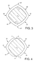
- the surface grinding provides a ground surface A which is tangent to a maximum diameter position D lying on the root at the corresponding protruding portion 20' and which is perpendicular to a radius OD connecting the maximum diameter position D and a rotational center O, in the cross section of the full-form thread portion 18 as shown in Fig. 2.
- a flute 26 On the ground surface A formed by grinding off the protruding portion 20', there is formed a flute 26 extending parallel to the axis of the cold forming tap 10 and having in its cross section a semi-circular shape, so as to form a cutting edge 24 at the maximum diameter position D corresponding to the root.
- the cutting edge 24 serves to finish the minor diameter of the internal thread to be formed.
- the protruding portions 20 which are not removed cooperate with each other to define an outside diameter smaller than that of the removed protruding portions 20'.
- the thread at the full-form thread portion 18, which is formed in a single thread grinding step, has a constant depth. Further, the thread is formed in the thread grinding step such that a crest diameter (2 x OB) of the non-removed protruding portions 20 is equal to a root diameter of the internal thread to be formed, and such that a root diameter (2 x OD) of the protruding portions 20' is equal to a minor diameter (crest diameter) of the internal threads to be formed.
- the crest diameter of the non-removed protruding portions 20 is smaller than a crest diameter of the removed protruding portions 20', and a root diameter (2 x OE) of the non-removed protruding portions 20 is smaller than the root diameter (2 x OD) of the removed protruding portions 20'.
- the cutting edge 24 is defined by the flute 26, and is formed at a minimum diameter position on the ground surface A, which minimum diameter position corresponds to the root diameter (2 x OD) of the protruding portions 20'.
- the diameter of a rotary locus of the cutting edge 24, i.e., the root diameter (2 x OD) of the protruding portions 20' is made equal to the minor diameter of the internal thread to be formed.
- a grinding wheel having a thread profile formed on an outer circumferential surface thereof is employed to form a thread on an outer circumferential surface of a bar-like blank which is made of a comparatively highly durable metallic material such as tool steel, high-speed steel or alloy steel and which has been cut to have a predetermined length.
- the external thread portion 14 having in its cross section a substantially rectangular shape defined by four sides each of which is outwardly arched, is formed at the free end portion of the bar-like blank, as shown in Fig.
- the thread of the external thread portion 14 which extends along a helix having a predetermined lead angle is provided with the four radially outwardly protruding portions 20, 20' and the relief portions 22, 22' which are adjacent to and have a diameter smaller than the protruding portions 20, 20'.
- the depth of the above-indicated thread of the external thread portion 14 is equal to that of the thread profile formed on the outer circumferential surface of the grinding wheel, and is constant at least at the full-form thread portion 18.
- the bar-like blank is positioned at four different positions which are angularly spaced apart from each other at the angular interval of 90° in the circumferential direction of the bar-like blank, and is held at the respective positions.
- the outer circumferential surface of the bar-like blank is ground by the rotating grinding wheel while the bar-like blank is moved along an arc whose center is located at a center of curvature of the corresponding one of the four sides, for thereby forming the thread of the cold forming tap 10, such that the root diameter (2 x OD) of the protruding portions 20' is equal to the minor diameter (crest diameter) of the internal thread to be formed, and such that the crest diameter (2 x OB) of the protruding portions 20 is equal to the root diameter of the internal thread to be formed.
- a protruding-portion removing step the protruding portions 20' which correspond to every two protruding portions 20, 20' successively arranged adjacent to each other in the helical direction is removed down to the root, by grinding the protruding portions 20' in a direction in which the every two protruding portions 20' is adjacent to each other at an interval of one lead of the thread, i.e., in the direction parallel to the axis of the cold forming tap 10, in the present embodiment.
- This protruding-portion removing step provides the ground surfaces A as shown in Fig. 4.
- the flute 26 is formed by grinding, on the upstream side, as viewed in the rotating direction of the cold forming tap 10, of a line indicative of the minimum diameter position of each of the ground surfaces A, as shown in Fig. 2.
- the flute 26 defines the cutting edge 24 which extends along the above-indicated line.
- a grinding wheel whose outer circumferential grinding surface has a cross sectional shape substantially identical with a cross sectional shape of the flute 26.
- Fig. 5 shows a process in which the internal thread is formed by using the cold forming tap 10 of the present embodiment constructed as described above.
- a high-precision internal thread 32 is formed on the surface of the hole previously formed in the workpiece 30. That is, the tapered leading portion 16 of the cold forming tap 10 is first screwed into the hole and forced into the surface of the prepared hole shown in Fig. 5(a), and the surface of the hole begins to be plastically deformed as shown in Fig. 5(b).
- the cold forming tap 10 is capable of forming the internal thread 32 with high precision in its minor diameter, even where the hole is a tapered hole which has been formed through a member made of a die-cast light alloy known as AC2C, for example, during the casting process and whose dimension is difficult to control.
- the above-indicated tapered hole has a diameter of 11.30mm at an entrance end thereof and a diameter of 10.80mm at an exit end thereof which is 18mm distant from the entrance end, while a normally recommended range of the diameter of the prepared hole for forming an internal thread of class 6H is 11.34-11.41mm.
- the cold forming tap 10 is constructed such that the protruding portions 20' of the protruding portions 20, 20', which are adjacent to each other in the axial direction are removed down to the root, and the cutting edge 24 having a diameter equal to the minor diameter of the internal thread 32 to be formed is formed at the portion corresponding to the root of each removed protruding portion 20'. Accordingly, the cutting edge 24 serves to remove the surplus stock 34, which has been displaced inwardly from a maximum root diameter of the external thread portion 14 as a result of the plastic deformation caused by the bite of the external thread portion 14 into the surface of the prepared hole, resulting in the formation of the high-precision internal thread 32. Further, the removal of the surplus stock 34 by the cutting edge 24 is effective to reduce a cold forming load acting on the tap 10, suitably preventing the tap 10 from being broken due to an excessive torque, even where the prepared hole has an inside diameter smaller than the lower limit.
- the maximum diameter position of the root is not located at the relief portions 22, 22' which are adjacent to the protruding portions 20, 20' of the external thread portion 14, and a concave-convex shape defined by the crest and a concave-convex shape defined by the root coincide with each other as viewed in the circumferential direction of the cold forming tap 10.
- Fig. 6 is a cross sectional view showing an external thread portion of a conventional cold forming tap 40 having internal finish cutting edges.
- protruding portions 42 are formed at the ridge of the external thread portion, and protruding portions 44 are formed at the root of the external thread portion, respectively.
- a flute 46 is formed between each two of the protruding portions 42 which is adjacent to each other, whereby cutting edges 48 cooperating with each other to have the maximum root diameter are formed at the respective protruding portions 44 formed at the root. Accordingly, a concave-convex shape defined by the crest and a concave-convex shape defined by the root do not coincide with each other as viewed in the circumferential direction of the cold forming tap 40.
- the thread of the external thread portion can not be formed in a single thread grinding step in which the thread is formed by a grinding wheel having a thread profile formed on an outer circumferential surface thereof.
- the formation of the external thread portion requires a plurality of different thread grinding steps so that the ridge and root are formed separately from each other in the respective different steps.
- the separate grinding operations not only complicate the production process, but also make it difficult to control the dimensions of the thread.
- Fig. 7 is a cross sectional view showing an external thread portion of a cold forming tap 50 according to another embodiment of the present invention.
- each of portions corresponding to the protruding portions 20 has a wear-resistant material 52, such as cemented carbide or an extra-high-pressure sintered body, which is embedded and cemented in the portion.
- a wear-resistant material 52 such as cemented carbide or an extra-high-pressure sintered body, which is embedded and cemented in the portion.
- the cold forming tap 50 of the present embodiment may be made of tool steel, high-speed steel or alloy steel, as a bar-like blank 54 which has been cut to have a predetermined length as shown in Fig. 8.
- a plurality of strips of the wear-resistant material 52 are first embedded in the outer circumferential surface of the bar-like blank 54, so as to spirally extend.
- the protruding portions 20, 20' are formed at the portions at which the strips of the wear-resistant material 52 are embedded, whereby each pair of the protruding portions 20, 20' which are spaced apart from each other by a distance equal to the lead are spirally adjacent to each other in the axial direction, while the ground surfaces A and the flutes 26 are also formed to spirally extend.
- the protruding portions 20 and the cutting edges 24 which receive a larger friction load than the other parts of the tap 50 are constituted by the wear-resistant material 52 such as cemented carbide, assuring excellent precision of the formed thread for a long period while preventing a breakage of the tap more effectively than where the entirety of the tap is made of cemented carbide.
- Fig. 9 shows a cross section of an external thread portion of a cold forming tap 60 according to a further embodiment of this invention.
- the external thread portion has a substantially hexagonal cross sectional shape defined by six sides each of which is outwardly arched, wherein the protruding portions 20 are equi-angularly spaced apart from each other at the angular interval of 60°.
- the protruding portions 20' each of which corresponds to every second of the protruding portions 20, 20' formed along the helix are removed, and the flutes 26 are formed such that the portions corresponding to the root of the protruding portions 20', i.e., the maximum diameter positions of the root diameter constitute the cutting edges 24.
- Fig. 10 shows a cross section of an external thread portion of a cold forming tap 62 according to a still further embodiment of this invention.
- the protruding portions 20 are equi-angularly spaced apart from each other at the angular interval of 120° in a circumferential direction of the tap 62.
- the protruding portion 20' is formed between a pair of the protruding portions 20, and the protruding portion 20' is removed down to the root.
- the flute 26 is formed such that the portion corresponding to the root of the protruding portion 20', i.e.. the maximum diameter position of the root diameter constitutes the cutting edge 24.
- Fig. 11 is a view in enlargement showing an essential portion of a cold forming tap 64 according to a still further embodiment of this invention.
- the flute 26 is formed to extend in the axial direction of the tap 64 throughout the full-form thread portion 18 and a portion of the tapered leading portion 16 which is adjacent to the full-form thread portion 18. That is, the flute 26 extends up to a terminal end thereof which is located at the tapered leading portion 16.
- the flute 26 is thus formed, due to the following two reasons in the present embodiment. Namely, the depth of the flute 26 is smaller than that in the embodiment shown in Fig. 1, and the taper angle of the tapered leading portion 16 is larger than that in the embodiment shown in Fig. 1.
- the flute 26 will be formed as described above.
- the oil groove 66 has a width smaller than that of the flute 26, and has a rectangular shape in cross section.
- the oil groove 66 is preferably formed so as to extend in a direction which is inclined with respect to the axis of the tap 64, by an angle substantially equal to a half of the taper angle ⁇ of the tapered leading portion 16, i.e., by an angle defined by right and left straight lines extending along the tapered leading portion 16 and intersecting each other as shown in Fig. 11.
- the present embodiment is advantageously capable of applying a lubricant oil to the internal thread which is being formed, owing to the provision of the oil groove 66 serving to communicate the terminal end of the flute 26 and the free end of the tapered leading portion 16, although the flute 26 does not extend throughout the external thread portion 14 in the axial direction.
- Fig. 12 is a view showing in enlargement an essential part of a cold forming tap 70 according to a still further embodiment of this invention.
- a second ground surface A' and a second flute 26' are formed throughout the tapered leading portion 16 in the axial direction.
- the second ground surface A' is obtained by removing the protruding portions 20' down to the root by surface grinding.
- the second flute 26' is located adjacent to the flute 26.
- the second ground surface A' and the ground surface A have the same cross sectional shape with each other, and the second flute 26' and the flute 26 have the identical cross sectional shape with each other.
- the second ground surface A' and the second flute 26' extend in a direction inclined with respect to the axis of the tap 70 by an angle substantially equal to a half of the taper angle of the tapered leading portion 16, for forming a second cutting edge 24' which extends throughout the tapered leading portion 16 in the axial direction and which is obtained by removing those of the protruding portions 20, 20' which are axially adjacent to each other, down to the root.
- the second cutting edge 24' serves to remove the surplus stock reaching the root of the thread at the tapered leading portion 16 which receives a larger cold forming load than the other portions of the tap.
- the second cutting edge 24' is effective to reduce the torque acting on the tap 70 and suitably prevent a breakage of the tap 70 even where an internal thread is to be formed in a small hole, e.g., a tapered hole formed in the casting process of the workpiece.
- the protruding portions 20' each of which corresponds to every second or every third of the protruding portions 20, 20' formed along the predetermined helix are removed.
- every desired number of the protruding portions 20, 20' may be removed down to the root, provided the desired number is a number which is a divisor of the number of the protruding portions 20, 20' per lead of the external thread portion 14 and which is other than "one", so that the removed protruding portions 20' are located successively and adjacently to each other in the axial direction.
- protruding portions 20, 20' per lead of the external thread portion 14 for example, every second protruding portions 20' (two protruding portions per lead) or every fourth protruding portions 20' (one protruding per lead) is removed.
- every second protruding 20' three protruding portions per lead
- every third protruding portions 20' two protruding portions per lead
- every sixth protruding portions 20' one protruding per lead
- the cutting edge 24 and the flute 26 are both formed to extend throughout the external thread portion 14 in the axial direction.
- the cutting edge 24 and the flute 26 may be formed at both or either of a portion of the external thread portion 14 and a portion of the tapered leading portion 16.
- This arrangement also offers substantially the same effect as in the embodiment of Fig. 1.
- the above-indicated portion of the external thread portion 14 preferably consists of a portion of the external thread portion 14 which is adjacent to the tapered leading portion 16, and an entire axial length of the tapered leading portion 16.
- the above-indicated portion of the tapered leading portion 16 preferably consists of a portion of the tapered leading portion 16 which is adjacent to the full-form thread portion 18.
- the ground surfaces A and the flutes 26 are formed to extend linearly and parallel to the axis of the cold forming tap 10.
- the ground surfaces A and the flutes 26 may be formed to helically extend, and oil grooves may be formed independently of the flutes 26 so as to linearly or helically extend throughout the entire axial length of the external thread portion 14. In the latter case, the oil grooves may communicate with the flutes 26 on the way in the axial direction.
- each of the cold forming taps 10, 50, 60, 62, 64, 70 of the above-described embodiments may have a surface which is hardened by a suitable nitriding treatment or coated with a coating material such as TiN or TiCN, or alternatively the entire body of the tap may consist of high-speed steel having a hardness of HRC 64-70, cemented carbide having a hardness of HRC 85-95, or fine-grain cemented carbide.
- each of the cutting edges 24 may have a surface which is coated with a hard carbon film.
- the diameter of the cutting edges 24, i.e., the maximum diameter of the root is equal to the minor diameter of the internal thread. This means that the diameter of the cutting edges 24 is determined to be substantially within a required tolerance of the minor diameter of the internal thread to be formed.
- the protruding portions 20 are formed to have the same height.
- these protruding portions 20 may have different heights such that the height of a downstream one of the adjacent two protruding portions 20 as viewed in the rotating direction is larger than that of the other protruding portion 20 which is located on the upstream side of the above-indicated downstream one of the adjacent two protruding portions 20, so that all of the protruding portions 20 are uniformly loaded with the plastic deformation resistance.
- This arrangement is effective to suitably prevent the protruding portions 20 from being broken, leading to improved durability of the cold forming tap.
- the cold forming tap having the internal finish cutting edge is suitable for forming an internal thread by plastic deformation.
Claims (20)
- Kaltformungs-Gewindebohrer mit einer Innenbearbeitungs-Schneidkante, der einen Außengewindeabschnitt enthält, an welchem ein Außengewinde, das eine einheitliche Tiefe hat, derart ausgebildet ist, dass es sich in eine vorbestimmte Richtung erstreckt, wobei der Außengewindeabschnitt radial auswärts vorstehende Abschnitte und ausgesparte Abschnitte enthält, welche an die vorstehenden Abschnitte angrenzen und einen Durchmesser kleiner als die vorstehenden Abschnitte haben, wobei die vorstehenden Abschnitte und die ausgesparten Abschnitte in der vorbestimmten Richtung abwechselnd angeordnet sind, so dass die vorstehenden Abschnitte in einem vorbestimmten Winkelabstand in einer Umfangsrichtung des Kaltformungs-Gewindebohrers winkelig voneinander beabstandet sind, und so dass die ausgesparten Abschnitte in einem vorbestimmten Winkelabstand in der Umfangsrichtung winkelig voneinander beabstandet sind, wobei die vorstehenden Abschnitte in eine Fläche eines vorbereiteten Lochs gedrückt werden, welches in einem Werkstück ausgebildet worden ist, um das Werkstück plastisch zu verformen, wodurch in der Fläche ein Innengewinde ausgebildet wird, wobei der Kaltformungs-Gewindebohrer dadurch gekennzeichnet ist, dass: mindestens einer der vorstehenden Abschnitte, welche innerhalb jeder Ganghöhe des Außengewindeabschnitts angeordnet sind, einen Kerndurchmesser hat, der größer als der der anderen der vorstehenden Abschnitte ist, wobei mindestens einer der vorstehenden Abschnitte nach unten bis zu einer Fläche entfernt ist, welche die maximale Durchmesser-Position tangiert, die an dem Kern des mindestens einen Abschnitts liegt, und eine Spannut ausgebildet ist, welche die Fläche an dem maximalen Durchmesser schneidet, um die Innenbearbeitungs-Schneidkante zu schaffen.
- Kaltformungs-Gewindebohrer mit einer Innenbearbeitungs-Schneidkante gemäß Anspruch 1, bei welchem der Außengewindeabschnitt einen kegelförmig zulaufenden vornliegenden Abschnitt und einen voll ausgebildeten Gewindeabschnitt enthält, welcher an eines der entgegengesetzten Enden des kegelförmig zulaufenden vornliegenden Abschnitts angrenzt, das einem proximalen Ende des Kaltformungs-Gewindebohrers näher ist, wobei der kegelförmig zulaufende vornliegende Abschnitt einen Außendurchmesser hat, der in eine Richtung auf ein freies Ende des Kaltformungs-Gewindebohrers zu abnimmt, während der voll ausgebildete Gewindeabschnitt einen konstanten Außendurchmesser hat, wobei die Schneidkante in dem voll ausgebildeten Gewindeabschnitt einen Durchmesser gleich einem kleineren Durchmesser des Innengewindes hat.
- Kaltformungs-Gewindebohrer mit einer Innenbearbeitungs-Schneidkante gemäß Anspruch 1 oder 2, bei welchem jede vorbestimmte Anzahl der vorstehenden Abschnitte nach unten bis zu dem Kern entfernt ist, wobei die vorbestimmte Anzahl gleich einer Anzahl ist, welche ein Teiler der Anzahl der vorstehenden Abschnitte pro Ganghöhe des Außengewindes ist und welche eine andere als "eins" ist.
- Kaltformungs-Gewindebohrer mit einer Innenbearbeitungs-Schneidkante gemäß einem der Ansprüche 1-3, wobei die Spannut in einem Anschnitt entsprechend dem Kern des mindestens einen der vorstehenden Abschnitte ausgebildet ist, um die Innenbearbeitungs-Schneidkante in dem Abschnitt entsprechend dem Kern zu schaffen, und eine Vielzahl der vorstehenden Abschnitte auf einer stromabwärts gelegenen Seite der Schneikante, betrachtet in einer Drehrichtung des Kaltformungs-Gewindebohrers, angeordnet sind, wobei die Vielzahl der vorstehenden Abschnitte unterschiedliche Höhen hat, so dass die Höhe eines stromabwärts gelegenen der angrenzenden zwei vorstehenden Abschnitte, betrachtet in der Drehrichtung, größer als der andere der angrenzenden zwei vorstehenden Abschnitte ist, welcher auf einer stromaufwärts gelegenen Seite des stromabwärts gelegenen, betrachtet in der Drehrichtung, angeordnet ist.
- Kaltformungs-Gewindebohrer mit einer Innenbearbeitungs-Schneidkante gemäß einem der Ansprüche 1-4, bei welchem die vorstehenden Abschnitte, welche nach unten bis zu dem Kern entfernt worden sind und welche in der axialen Richtung aneinander angrenzen, über eine gesamte axiale Länge des Außengewindeabschnitts ausgebildet sind.
- Kaltformungs-Gewindebohrer mit einer Innenbearbeitungs-Schneidkante gemäß einem der Ansprüche 1-5, bei welchem die Spannut über eine gesamte axiale Länge des kegelförmig zulaufenden vornliegenden Abschnitts ausgebildet ist.
- Kaltformungs-Gewindebohrer mit einer Innenbearbeitungs-Schneidkante gemäß einem der Ansprüche 1-5, bei welchem die Spannut über eine gesamte axiale Länge des kegelförmig zulaufenden vornliegenden Abschnitts und einen Abschnitt des voll ausgebildeten Gewindeabschnitts ausgebildet ist, welcher angrenzend dem kegelförmig zulaufenden vornliegenden Abschnitt ist.
- Kaltformungs-Gewindebohrer mit einer Innenbearbeitungs-Schneidkante gemäß einem der Ansprüche 1-5, bei welchem die Spannut über einen Abschnitt des voll ausgebildeten Gewindeabschnitts, welcher angrenzend dem kegelförmig zulaufenden vornliegenden Abschnitt ist, und einen Abschnitt des kegelförmig zulaufenden vornliegenden Abschnitts ausgebildet ist, welcher angrenzend dem voll ausgebildeten Gewindeabschnitt ist.
- Kaltformungs-Gewindebohrer mit einer Innenbearbeitungs-Schneidkante gemäß einem der Ansprüche 1-8, bei welchem der mindestens eine der vorstehenden Abschnitte in dem kegelförmig zulaufenden vornliegenden Abschnitt nach unten bis zu dem Kern entlang einer Ebene entfernt ist, welche bezüglich einer Achse des Kaltformungs-Gewindebohrers um einen Winkel geneigt ist, der im wesentlichen gleich einer Hälfte eines Kegelwinkels des kegelförmig zulaufenden vornliegenden Abschnitts ist, und eine Spannut in einem Abschnitt entsprechend dem Kern des mindestens einen der vorstehenden Abschnitte in dem kegelförmig zulaufenden vornliegenden Abschnitt ausgebildet ist, um eine Schneidkante in dem Abschnitt entsprechend dem Kern des mindestens einen der vorstehenden Abschnitte in dem kegelförmig zulaufenden vornliegenden Abschnitt zu schaffen.
- Kaltformungs-Gewindebohrer mit einer Innenbearbeitungs-Schneidkante gemäß Anspruch 8, bei welchem in dem kegelförmig zulaufenden vornliegenden Abschnitt eine Ölnut derart ausgebildet ist, dass die Ölnut angrenzend der Spannut ist und sich nach oben zu einem freien Ende des kegelförmig zulaufenden vornliegenden Abschnitts erstreckt.
- Kaltformungs-Gewindebohrer mit einer Innenbearbeitungs-Schneidkante gemäß Anspruch 10, bei welchem die Ölnut in einer Ebene ausgebildet ist, welche bezüglich einer Achse des Kaltformungs-Gewindebohrers um einen Winkel geneigt ist, der im wesentlichen gleich einer Hälfte eines Kegelwinkels des kegelförmig zulaufenden vornliegenden Abschnitts ist.
- Kaltformungs-Gewindebohrer mit einer Innenbearbeitungs-Schneidkante gemäß einem der Ansprüche 1-9, der ferner eine Ölnut enthält, welche über eine gesamte axiale Länge des Außengewindeabschnitts ausgebildet ist.
- Kaltformungs-Gewindebohrer mit einer Innenbearbeitungs-Schneidkante gemäß einem der Ansprüche 1-12, bei welchem die Spannut und der mindestens eine der vorstehenden Abschnitte, welcher nach unten bis zu dem Kern entfernt worden ist, derart ausgebildet sind, dass sie sich linear und parallel zu der Achse des Kaltformungs-Gewindebohrers erstrecken.
- Kaltformungs-Gewindebohrer mit einer Innenbearbeitungs-Schneidkante gemäß einem der Ansprüche 1-12, bei welchem die Spannut und der mindestens eine der vorstehenden Abschnitte, welcher nach unten bis zu dem Kern entfernt worden ist, derart ausgebildet sind, dass sie sich schraubenförmig und parallel zu der Achse des Kaltformungs-Gewindebohrers erstrecken.
- Kaltformungs-Gewindebohrer mit einer Innenbearbeitungs-Schneidkante gemäß einem der Ansprüche 1-12, bei welchem der Außengewindeabschnitt eine Polygonalform hat, die durch Seiten definiert ist, von denen jede auswärts gekrümmt ist.
- Kaltformungs-Gewindebohrer mit einer Innenbearbeitungs-Schneidkante gemäß einem der Ansprüche 1-15, bei welchem der Außengewindeabschnitt eine im wesentlichen quadratische Querschnittsform hat, die durch vier Seiten definiert ist, von denen jede auswärts gekrümmt ist.
- Kaltformungs-Gewindebohrer mit einer Innenbearbeitungs-Schneidkante gemäß einem der Ansprüche 1-15, bei welchem der Außengewindeabschnitt eine im wesentlichen hexagonale Querschnittsform hat, die durch sechs Seiten definiert ist, von denen jede auswärts gekrümmt ist.
- Kaltformungs-Gewindebohrer mit einer Innenbearbeitungs-Schneidkante gemäß einem der Ansprüche 1-15, bei welchem der Außengewindeabschnitt eine im wesentlichen dreieckige Querschnittsform hat, die durch drei Seiten definiert ist, von denen jede auswärts gekrümmt ist.
- Kaltformungs-Gewindebohrer mit einer Innenbearbeitungs-Schneidkante gemäß einem der Ansprüche 1-18, bei welchem mindestens die vorstehenden Abschnitte und ein Abschnitt der Schneidkante, welche in dem kegelförmig zulaufenden vornliegenden Abschnitt angeordnet sind, durch ein Sinterkarbid gebildet sind, welches an einem Umfangsabschnitt eines Körpers des Kaltformungs-Gewindebohrers befestigt ist, welcher aus einem legiertem Stahl gefertigt ist.
- Verfahren zur Herstellung eines Kaltformungs-Gewindebohrers gemäß Anspruch 1, wobei das Verfahren enthält: einen Gewindeschleifschritt zum Schleifen einer äußeren Umfangsfläche von einem von entgegengesetzten Endabschnitten eines stabähnlichen Rohlings durch Anwendung einer Schleifscheibe, die eine äußere Umfangsfläche hat, auf welcher ein Gewindeprofil ausgebildet ist, um das Außengewinde auszubilden, das einen einheitlichen Abstand zwischen einer Spitze und einem Kern des Außengewindes hat, so dass mindestens einer der vorstehenden Abschnitte, welche innerhalb jeder Ganghöhe des Außengewindeabschnitts angeordnet sind, einen Kerndurchmesser hat, der größer als der der anderen der vorstehenden Abschnitte ist, wobei das Gewindeprofil einen Abstand zwischen einer Spitze und einem Kern des Gewindeprofils hat, welcher gleich dem einheitlichen Abstand ist;
einen Schritt zur Entfernung des vorstehenden Abschnitts, um den mindestens einen der vorstehenden Abschnitte, welche in dem Gewindeschleifschritt ausgebildet worden sind, nach unten bis zu einer Fläche zu entfernen, welche die maximale Durchmesser-Position tangiert, die an dem Kern des mindestens einen Abschnitts liegt; und
einen Spannnut-Ausbildungsschritt zur Ausbildung einer Spannut in der Fläche, welche als ein Ergebnis der Entfernung jedes des mindestens einen der vorstehenden Abschnitte in dem Schritt zur Entfernung des vorstehenden Abschnitts erzielt worden ist, so dass auf einer stromaufwärts gelegenen Seite einer Linie, betrachtet in einer Drehrichtung des Kaltformungs-Gewindebohrers, eine Schneidkante geschaffen wird, wobei die Linie eine minimale Durchmesser-Position repräsentiert, die an der in dem Schritt zur Entfernung des vorstehenden Abschnitts erzielten Fläche liegt.
Applications Claiming Priority (1)
| Application Number | Priority Date | Filing Date | Title |
|---|---|---|---|
| PCT/JP1997/002473 WO1999003631A1 (fr) | 1996-02-09 | 1997-07-16 | Taraud de formage a froid avec couteau de finissage du diametre interne et procede de fabrication correspondant |
Publications (3)
| Publication Number | Publication Date |
|---|---|
| EP0933157A1 EP0933157A1 (de) | 1999-08-04 |
| EP0933157A4 EP0933157A4 (de) | 2000-10-04 |
| EP0933157B1 true EP0933157B1 (de) | 2004-06-09 |
Family
ID=14180839
Family Applications (1)
| Application Number | Title | Priority Date | Filing Date |
|---|---|---|---|
| EP97930814A Expired - Lifetime EP0933157B1 (de) | 1997-07-16 | 1997-07-16 | Kaltformgewindebohrer mit inner diameter feinbearbeitungseinsatz und dessen herstellungsmethode |
Country Status (8)
| Country | Link |
|---|---|
| US (1) | US6217267B1 (de) |
| EP (1) | EP0933157B1 (de) |
| AT (1) | ATE268663T1 (de) |
| BR (1) | BR9711292A (de) |
| CA (1) | CA2265529C (de) |
| CZ (1) | CZ287834B6 (de) |
| DE (1) | DE69729467T2 (de) |
| WO (1) | WO1999003631A1 (de) |
Cited By (1)
| Publication number | Priority date | Publication date | Assignee | Title |
|---|---|---|---|---|
| DE102005010543A1 (de) * | 2005-03-04 | 2006-09-07 | EMUGE-Werk Richard Glimpel GmbH & Co. KG Fabrik für Präzisionswerkzeuge | Werkzeug und Verfahren zur Erzeugung oder Nachbearbeitung eines Gewindes |
Families Citing this family (40)
| Publication number | Priority date | Publication date | Assignee | Title |
|---|---|---|---|---|
| SE519067C2 (sv) * | 2001-05-22 | 2003-01-07 | Sandvik Ab | Gängtapp med lobformat tvärsnitt och gängslappningsparti |
| SE522125C2 (sv) * | 2001-05-22 | 2004-01-13 | Sandvik Ab | Gängverktyg med ringformig kam |
| JP3609366B2 (ja) * | 2001-10-22 | 2005-01-12 | オーエスジー株式会社 | 盛上げタップ |
| US6688988B2 (en) | 2002-06-04 | 2004-02-10 | Balax, Inc. | Looking thread cold forming tool |
| SE0300224L (sv) * | 2003-01-30 | 2004-06-29 | Sandvik Ab | En gängtapp för att skära gängor i bottenhål och metoder för dess tillverkning |
| DE10332930A1 (de) * | 2003-07-19 | 2005-02-03 | Sandvik Ab | Gewindebohrer |
| US7144208B2 (en) * | 2004-06-07 | 2006-12-05 | Kennametal Inc. | Low torque tap |
| DE102005022503B4 (de) | 2004-09-13 | 2019-10-17 | EMUGE-Werk Richard Glimpel GmbH & Co. KG Fabrik für Präzisionswerkzeuge | Werkzeug und Verfahren zur Erzeugung eines Gewindes |
| DE102004052455A1 (de) * | 2004-10-28 | 2006-05-04 | Volkswagen Ag | System und Verfahren zur Gewindeherstellung in vergüteten Stählen |
| DE102004059264B4 (de) * | 2004-12-08 | 2007-02-22 | EMUGE-Werk Richard Glimpel GmbH & Co. KG Fabrik für Präzisionswerkzeuge | Werkzeug und Verfahren zur Erzeugung eines Gewindes in einem Werkstück |
| WO2006117850A1 (ja) * | 2005-04-27 | 2006-11-09 | Osg Corporation | 盛上げタップおよびその製造方法 |
| JP3927589B1 (ja) * | 2006-01-17 | 2007-06-13 | 酒井精工株式会社 | 回転切削工具および回転切削工具の製造方法 |
| WO2007086112A1 (ja) * | 2006-01-25 | 2007-08-02 | Osg Corporation | 焼きばめ式工具ユニット及びその焼きばめ式工具ユニットに使用される工具ホルダ並びに回転工具 |
| US7927221B2 (en) * | 2006-03-14 | 2011-04-19 | Emuge-Werk Richard Glimpel Gmbh & Co. | Tool and method for the production of a thread |
| US7665934B2 (en) * | 2006-10-18 | 2010-02-23 | Kennametal Inc. | Cutting tap and method of making a cutting tap |
| US20090317203A1 (en) * | 2006-12-18 | 2009-12-24 | Osg Corporation | Spiral fluted tap |
| US8186915B2 (en) * | 2007-04-26 | 2012-05-29 | Osg Corporation | Spiral tap |
| US20090074526A1 (en) * | 2007-09-18 | 2009-03-19 | Yg-1 Co., Ltd. | Compound Relief Tap |
| CN101977718B (zh) * | 2008-03-21 | 2013-02-27 | Osg株式会社 | 冷成型丝锥 |
| US8210779B2 (en) * | 2008-10-14 | 2012-07-03 | Kennametal Inc. | Cutting tap and method of making same |
| DE102008053772A1 (de) * | 2008-10-22 | 2010-04-29 | Komet Jel Precision Tools | Gewindeformer |
| DE112009005043B4 (de) * | 2009-07-07 | 2021-12-30 | Osg Corp. | Gewindeausbildungsbohrer |
| US8602696B2 (en) * | 2009-10-09 | 2013-12-10 | Harry Leroy Ellis | Form tap having a plurality of lobes |
| DE112010005123B4 (de) | 2010-01-13 | 2021-10-21 | Osg Corporation | Plastisch verformendes gewindeschneidwerkzeug mit innendurchmesserendbearbeitungskanten |
| DE102012105183B4 (de) * | 2012-06-14 | 2013-12-24 | Audi Ag | Verfahren und ein Werkzeug jeweils zum Erzeugen eines Gewindes in einem Werkstück |
| JP5951040B2 (ja) * | 2012-11-07 | 2016-07-13 | オーエスジー株式会社 | 盛上げタップの製造方法 |
| DE102013101003A1 (de) | 2013-01-31 | 2014-07-31 | Walter Ag | Gewindeformer und Verfahren zur spanlosen Herstellung von Gewinden |
| CN104227151A (zh) * | 2013-06-19 | 2014-12-24 | 许灵生 | 丝攻刀具 |
| US9682435B2 (en) * | 2014-08-28 | 2017-06-20 | Kennametal Inc. | Thread forming taps |
| USD769684S1 (en) | 2015-04-30 | 2016-10-25 | A & E Incorporated | Thread restorer tool |
| US11045287B2 (en) * | 2016-01-29 | 2021-06-29 | Nobel Biocare Services Ag | Dentistry tool |
| KR102162235B1 (ko) * | 2016-08-09 | 2020-10-06 | 오에스지 가부시키가이샤 | 나사 성형용 탭 및 나사 성형용 탭의 제조 방법 |
| EP3300825B1 (de) | 2016-09-28 | 2021-07-07 | Walter Ag | Gewindeformungswerkzeug |
| DE102016122701B4 (de) * | 2016-11-24 | 2023-10-26 | EMUGE-Werk Richard Glimpel GmbH & Co. KG Fabrik für Präzisionswerkzeuge | Gewindeformer und Verfahren zur Herstellung eines Gewindeformers |
| WO2018193515A1 (ja) * | 2017-04-18 | 2018-10-25 | オーエスジー株式会社 | 盛上げタップ |
| CN107309713B (zh) * | 2017-06-30 | 2019-03-29 | 苏州精协机械制造有限公司 | 一种确定螺纹磨床加工多棱挤压丝锥参数的方法 |
| DE102018126927A1 (de) * | 2018-10-29 | 2020-04-30 | EMUGE-Werk Richard Glimpel GmbH & Co. KG Fabrik für Präzisionswerkzeuge | Gewindeformer mit Bördelstegen |
| DE102019130009A1 (de) * | 2019-11-07 | 2021-05-12 | EMUGE-Werk Richard Glimpel GmbH & Co. KG Fabrik für Präzisionswerkzeuge | Werkzeug zur spanlosen Erzeugung oder Nachbearbeitung eines Gewindes, Verfahren zum Herstellen des Werkzeugs und Verfahren zum Herstellen eines Gewindes |
| USD921722S1 (en) * | 2020-05-26 | 2021-06-08 | Devin Corbit | Fluted tap |
| US11465221B2 (en) * | 2020-12-28 | 2022-10-11 | GM Global Technology Operations LLC | Hybrid threading tool with cutting portion and rolling portion |
Family Cites Families (23)
| Publication number | Priority date | Publication date | Assignee | Title |
|---|---|---|---|---|
| DE531510C (de) * | 1931-08-13 | Emil Baumann | Gewindebohrer, bei dem sich die von je zwei aufeinanderfolgenden Umfangsschneidkanten der Anschnittzaehne bestrichenen Flaechen kreuzen | |
| US274492A (en) * | 1882-11-14 | 1883-03-27 | Hayward A Harvey | Tap for cutting spiral wedge nuts |
| US992946A (en) * | 1910-02-28 | 1911-05-23 | Greenlee Bros & Company | Wood-tap. |
| US3069961A (en) * | 1960-01-04 | 1962-12-25 | Elastic Stop Nut Corp | Screw threaded member |
| US3226743A (en) | 1961-12-19 | 1966-01-04 | British Tap & Die Company | Fluteless taps |
| US3251080A (en) * | 1963-04-17 | 1966-05-17 | Wilfred J Sharon | Tool for forming screw threads by a cutting action followed by a swaging action |
| US3775792A (en) * | 1972-03-01 | 1973-12-04 | Vermont American Corp | Thread forming tap |
| DE2625863B2 (de) | 1976-06-09 | 1978-06-29 | Fa. Ernst Reime, 8500 Nuernberg | Gewindebohrer |
| FR2514679B1 (fr) | 1981-10-15 | 1987-01-09 | Creusot Loire | Taraud pour taraudages de grande precision dans des trous debouchants |
| JPS6015623A (ja) | 1983-07-07 | 1985-01-26 | Tokyo Optical Co Ltd | 眼鏡調整装置 |
| DE3419850A1 (de) | 1984-05-28 | 1985-11-28 | Süddeutsches Präzisionswerk GmbH & Co, 7340 Geislingen | Innengewinde-schneidwerkzeug |
| JPS61144916U (de) * | 1985-02-05 | 1986-09-06 | ||
| US4673323A (en) * | 1986-04-07 | 1987-06-16 | Peter Russo | Self tapping stud |
| JPH0637856Y2 (ja) * | 1988-06-16 | 1994-10-05 | オーエスジー株式会社 | 盛上げタップ |
| JPH0669646B2 (ja) * | 1988-10-13 | 1994-09-07 | オーエスジー株式会社 | 盛上げタップ |
| US5037251A (en) * | 1989-03-24 | 1991-08-06 | Roth Alfred C | Thread tap |
| US5035019A (en) * | 1989-10-11 | 1991-07-30 | North Attleboro Taps, Inc. | Cold-forming tap |
| JPH0388627U (de) * | 1989-12-27 | 1991-09-10 | ||
| HU214896B (hu) * | 1993-02-11 | 1998-07-28 | László Vilmányi | Menetfúró forgácsolószerszám |
| US5562371A (en) * | 1995-06-07 | 1996-10-08 | Lock-N-Stitch International | Tap with a non-cutting pilot |
| JP2880122B2 (ja) * | 1995-10-02 | 1999-04-05 | 株式会社田野井製作所 | 盛上げタップ |
| DE29518075U1 (de) | 1995-11-15 | 1996-02-01 | Buchwald Willi | Werkzeug zur spanenden Formgebung von Gewinden |
| US5664915A (en) * | 1996-03-22 | 1997-09-09 | Hawke; Terrence C. | Tap and method of making a tap with selected size limits |
-
1997
- 1997-07-16 AT AT97930814T patent/ATE268663T1/de not_active IP Right Cessation
- 1997-07-16 CA CA002265529A patent/CA2265529C/en not_active Expired - Lifetime
- 1997-07-16 BR BR9711292A patent/BR9711292A/pt not_active IP Right Cessation
- 1997-07-16 DE DE69729467T patent/DE69729467T2/de not_active Expired - Lifetime
- 1997-07-16 CZ CZ1999610A patent/CZ287834B6/cs not_active IP Right Cessation
- 1997-07-16 EP EP97930814A patent/EP0933157B1/de not_active Expired - Lifetime
- 1997-07-16 WO PCT/JP1997/002473 patent/WO1999003631A1/ja active IP Right Grant
- 1997-07-16 US US09/242,453 patent/US6217267B1/en not_active Expired - Lifetime
Cited By (2)
| Publication number | Priority date | Publication date | Assignee | Title |
|---|---|---|---|---|
| DE102005010543A1 (de) * | 2005-03-04 | 2006-09-07 | EMUGE-Werk Richard Glimpel GmbH & Co. KG Fabrik für Präzisionswerkzeuge | Werkzeug und Verfahren zur Erzeugung oder Nachbearbeitung eines Gewindes |
| DE102005010543B4 (de) * | 2005-03-04 | 2009-04-09 | EMUGE-Werk Richard Glimpel GmbH & Co. KG Fabrik für Präzisionswerkzeuge | Werkzeug und Verfahren zur Erzeugung oder Nachbearbeitung eines Gewindes |
Also Published As
| Publication number | Publication date |
|---|---|
| CZ287834B6 (en) | 2001-02-14 |
| WO1999003631A1 (fr) | 1999-01-28 |
| CA2265529C (en) | 2002-09-10 |
| CA2265529A1 (en) | 1999-01-28 |
| EP0933157A4 (de) | 2000-10-04 |
| CZ61099A3 (cs) | 1999-12-15 |
| DE69729467D1 (de) | 2004-07-15 |
| ATE268663T1 (de) | 2004-06-15 |
| EP0933157A1 (de) | 1999-08-04 |
| US6217267B1 (en) | 2001-04-17 |
| DE69729467T2 (de) | 2005-06-16 |
| BR9711292A (pt) | 1999-08-17 |
Similar Documents
| Publication | Publication Date | Title |
|---|---|---|
| EP0933157B1 (de) | Kaltformgewindebohrer mit inner diameter feinbearbeitungseinsatz und dessen herstellungsmethode | |
| US7399231B2 (en) | Tool and method for producing a thread in a tool | |
| EP2346637B1 (de) | Gewindeschneider und herstellungsverfahren eines gewindeschneiders | |
| JP6266603B2 (ja) | ワークピースにねじ山を形成する方法および工具 | |
| US7950880B2 (en) | Spiral flute tap | |
| GB1569066A (en) | Thread forming screw with step taper and dies for making the same | |
| US20030078109A1 (en) | Thread forming tap | |
| US7114891B2 (en) | Thread forming tool with annular ridge | |
| WO2011086675A1 (ja) | 内径仕上げ刃付き盛上げタップ | |
| EP1066473A1 (de) | Selbstfurchende schraube und rohling dafür | |
| WO2004052577A2 (en) | Chamfer hob and method of using same | |
| JP2777100B2 (ja) | 内径仕上げ刃付き盛上げタップ | |
| US7815512B2 (en) | Thread forming tap and method for manufacturing the same | |
| CN109689261B (zh) | 螺纹形成刀具 | |
| US20230220867A1 (en) | Wood screw | |
| KR100310582B1 (ko) | 내경 다듬질날을 갖춘 콜드포밍탭 및 그 제조방법 | |
| US3131407A (en) | Thread swaging tap | |
| DE102005010543B4 (de) | Werkzeug und Verfahren zur Erzeugung oder Nachbearbeitung eines Gewindes | |
| US3237485A (en) | Method of tap manufacture | |
| US3295154A (en) | Metal swaging tool and method of seating and threading a thin walled cylinder in a hole | |
| US3390410A (en) | Thread swaging tap | |
| JP5241557B2 (ja) | セルフタッピングインサート | |
| JPH0214903Y2 (de) | ||
| JP2669779B2 (ja) | 転造用平ダイスおよびウォーム歯車 | |
| CA3193612A1 (en) | Wood screw |
Legal Events
| Date | Code | Title | Description |
|---|---|---|---|
| PUAI | Public reference made under article 153(3) epc to a published international application that has entered the european phase |
Free format text: ORIGINAL CODE: 0009012 |
|
| 17P | Request for examination filed |
Effective date: 19990219 |
|
| AK | Designated contracting states |
Kind code of ref document: A1 Designated state(s): AT BE CH DE DK ES FI FR GB GR IE IT LI |
|
| A4 | Supplementary search report drawn up and despatched |
Effective date: 20000823 |
|
| AK | Designated contracting states |
Kind code of ref document: A4 Designated state(s): AT BE CH DE DK ES FI FR GB GR IE IT LI |
|
| RIC1 | Information provided on ipc code assigned before grant |
Free format text: 7B 23G 5/06 A, 7B 23G 1/38 B, 7B 23G 7/02 B |
|
| GRAP | Despatch of communication of intention to grant a patent |
Free format text: ORIGINAL CODE: EPIDOSNIGR1 |
|
| GRAS | Grant fee paid |
Free format text: ORIGINAL CODE: EPIDOSNIGR3 |
|
| GRAA | (expected) grant |
Free format text: ORIGINAL CODE: 0009210 |
|
| AK | Designated contracting states |
Kind code of ref document: B1 Designated state(s): AT BE CH DE DK ES FI FR GB GR IE IT LI |
|
| PG25 | Lapsed in a contracting state [announced via postgrant information from national office to epo] |
Ref country code: LI Free format text: LAPSE BECAUSE OF FAILURE TO SUBMIT A TRANSLATION OF THE DESCRIPTION OR TO PAY THE FEE WITHIN THE PRESCRIBED TIME-LIMIT Effective date: 20040609 Ref country code: IT Free format text: LAPSE BECAUSE OF FAILURE TO SUBMIT A TRANSLATION OF THE DESCRIPTION OR TO PAY THE FEE WITHIN THE PRESCRIBED TIME-LIMIT;WARNING: LAPSES OF ITALIAN PATENTS WITH EFFECTIVE DATE BEFORE 2007 MAY HAVE OCCURRED AT ANY TIME BEFORE 2007. THE CORRECT EFFECTIVE DATE MAY BE DIFFERENT FROM THE ONE RECORDED. Effective date: 20040609 Ref country code: FR Free format text: LAPSE BECAUSE OF FAILURE TO SUBMIT A TRANSLATION OF THE DESCRIPTION OR TO PAY THE FEE WITHIN THE PRESCRIBED TIME-LIMIT Effective date: 20040609 Ref country code: FI Free format text: LAPSE BECAUSE OF FAILURE TO SUBMIT A TRANSLATION OF THE DESCRIPTION OR TO PAY THE FEE WITHIN THE PRESCRIBED TIME-LIMIT Effective date: 20040609 Ref country code: CH Free format text: LAPSE BECAUSE OF FAILURE TO SUBMIT A TRANSLATION OF THE DESCRIPTION OR TO PAY THE FEE WITHIN THE PRESCRIBED TIME-LIMIT Effective date: 20040609 Ref country code: BE Free format text: LAPSE BECAUSE OF FAILURE TO SUBMIT A TRANSLATION OF THE DESCRIPTION OR TO PAY THE FEE WITHIN THE PRESCRIBED TIME-LIMIT Effective date: 20040609 Ref country code: AT Free format text: LAPSE BECAUSE OF FAILURE TO SUBMIT A TRANSLATION OF THE DESCRIPTION OR TO PAY THE FEE WITHIN THE PRESCRIBED TIME-LIMIT Effective date: 20040609 |
|
| REG | Reference to a national code |
Ref country code: GB Ref legal event code: FG4D |
|
| REG | Reference to a national code |
Ref country code: CH Ref legal event code: EP |
|
| REF | Corresponds to: |
Ref document number: 69729467 Country of ref document: DE Date of ref document: 20040715 Kind code of ref document: P |
|
| PG25 | Lapsed in a contracting state [announced via postgrant information from national office to epo] |
Ref country code: IE Free format text: LAPSE BECAUSE OF NON-PAYMENT OF DUE FEES Effective date: 20040716 |
|
| REG | Reference to a national code |
Ref country code: IE Ref legal event code: FG4D |
|
| PG25 | Lapsed in a contracting state [announced via postgrant information from national office to epo] |
Ref country code: GR Free format text: LAPSE BECAUSE OF FAILURE TO SUBMIT A TRANSLATION OF THE DESCRIPTION OR TO PAY THE FEE WITHIN THE PRESCRIBED TIME-LIMIT Effective date: 20040909 Ref country code: DK Free format text: LAPSE BECAUSE OF FAILURE TO SUBMIT A TRANSLATION OF THE DESCRIPTION OR TO PAY THE FEE WITHIN THE PRESCRIBED TIME-LIMIT Effective date: 20040909 |
|
| PG25 | Lapsed in a contracting state [announced via postgrant information from national office to epo] |
Ref country code: ES Free format text: LAPSE BECAUSE OF FAILURE TO SUBMIT A TRANSLATION OF THE DESCRIPTION OR TO PAY THE FEE WITHIN THE PRESCRIBED TIME-LIMIT Effective date: 20040920 |
|
| REG | Reference to a national code |
Ref country code: CH Ref legal event code: PL |
|
| PLBE | No opposition filed within time limit |
Free format text: ORIGINAL CODE: 0009261 |
|
| STAA | Information on the status of an ep patent application or granted ep patent |
Free format text: STATUS: NO OPPOSITION FILED WITHIN TIME LIMIT |
|
| REG | Reference to a national code |
Ref country code: IE Ref legal event code: MM4A |
|
| 26N | No opposition filed |
Effective date: 20050310 |
|
| EN | Fr: translation not filed | ||
| PGFP | Annual fee paid to national office [announced via postgrant information from national office to epo] |
Ref country code: GB Payment date: 20160722 Year of fee payment: 20 Ref country code: DE Payment date: 20160728 Year of fee payment: 20 |
|
| REG | Reference to a national code |
Ref country code: DE Ref legal event code: R071 Ref document number: 69729467 Country of ref document: DE |
|
| REG | Reference to a national code |
Ref country code: GB Ref legal event code: PE20 Expiry date: 20170715 |
|
| PG25 | Lapsed in a contracting state [announced via postgrant information from national office to epo] |
Ref country code: GB Free format text: LAPSE BECAUSE OF EXPIRATION OF PROTECTION Effective date: 20170715 |