EP0931369B1 - Verfahren zum herstellen von kommutatoren und nach dem verfahren hergestellter kommutator - Google Patents
Verfahren zum herstellen von kommutatoren und nach dem verfahren hergestellter kommutator Download PDFInfo
- Publication number
- EP0931369B1 EP0931369B1 EP97909250A EP97909250A EP0931369B1 EP 0931369 B1 EP0931369 B1 EP 0931369B1 EP 97909250 A EP97909250 A EP 97909250A EP 97909250 A EP97909250 A EP 97909250A EP 0931369 B1 EP0931369 B1 EP 0931369B1
- Authority
- EP
- European Patent Office
- Prior art keywords
- basket
- segments
- commutator
- webs
- assembly
- Prior art date
- Legal status (The legal status is an assumption and is not a legal conclusion. Google has not performed a legal analysis and makes no representation as to the accuracy of the status listed.)
- Expired - Lifetime
Links
Images


Classifications
-
- H—ELECTRICITY
- H01—ELECTRIC ELEMENTS
- H01R—ELECTRICALLY-CONDUCTIVE CONNECTIONS; STRUCTURAL ASSOCIATIONS OF A PLURALITY OF MUTUALLY-INSULATED ELECTRICAL CONNECTING ELEMENTS; COUPLING DEVICES; CURRENT COLLECTORS
- H01R43/00—Apparatus or processes specially adapted for manufacturing, assembling, maintaining, or repairing of line connectors or current collectors or for joining electric conductors
- H01R43/06—Manufacture of commutators
-
- H—ELECTRICITY
- H01—ELECTRIC ELEMENTS
- H01R—ELECTRICALLY-CONDUCTIVE CONNECTIONS; STRUCTURAL ASSOCIATIONS OF A PLURALITY OF MUTUALLY-INSULATED ELECTRICAL CONNECTING ELEMENTS; COUPLING DEVICES; CURRENT COLLECTORS
- H01R39/00—Rotary current collectors, distributors or interrupters
- H01R39/02—Details for dynamo electric machines
- H01R39/04—Commutators
Definitions
- the invention relates to a method for producing commutators, in which a plurality of metallic segments in an assembly basket is used to form a segment association in which the segments in positionally insulated from one another and forming a commutation slideway are arranged, and the segment formation to form an insulating body with embedded segments with a press-formable, insulating Molding compound is pressed.
- the invention also relates to a Commutator manufactured by such a method.
- the procedure is such that after inserting the segments punched out of a metallic material in the mounting basket designed as a plastic basket and after Add any further components that may be provided, for example of reinforcement rings, the pressing is carried out, the cavities be filled in the segmental association with molding compound. Then the Plastic basket removed to be disposed of as special waste.
- EP-A2-325 353 shows a commutator in which the segments are on one electrically insulating, tubular base body by folding segment tabs at the end by 180 ° around the base body. Then the base body with the formation of a hub with plastic sprayed out and cast the bent tabs of the segments.
- US-A-3,643,314 shows a device for spacing the lamellae drum-shaped press commutator.
- the segments are divided into one inserted axially tapered mounting basket, this with a Pressed insulating compound and then the assembly basket mechanically removed or washed out with a solvent.
- a mechanical one Removal by twisting is particularly useful when the commutator must be turned over after completion.
- US-A-4,056,882 shows a method of making a geometry stable Commutators.
- the segments to be cast are separated by one Reinforcement ring made of steel, which is heated for insertion.
- the object of the present invention is a method to indicate that despite the use of the manufacturing process facilitating Mounting baskets a particularly inexpensive and environmentally friendly Manufacture of the commutators enables.
- this object is according to the invention solved in that the assembly basket together with the segment assembly is pressed with the molding compound in such a way that the assembly basket as a permanent integral component is molded into the insulating body.
- Commutator is included in the inventive method not just the cost of removing and disposing of the baskets, but it there are also no additional material costs for insulation material because of the Basket forms part of the insulating body of the commutator.
- thermosetting material is advantageously used to produce the baskets Material used, which also forms the molding compound during pressing. It results a particularly homogeneous structure of the insulating body thus formed.
- the commutator according to the invention produced by the method shown is characterized in that its insulating body one in the molding compound molded, serving as an insulating support body for the segmental association Includes mounting basket.
- a gradual expansion of the commutator according to the invention into one High-performance commutator results from the use of reinforcement rings and Pins to support them as further integral parts.
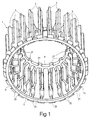
- thermosetting plastic press-molded basket 1 is used to produce a Commutator, the twenty-four copper segments 3 (see in particular Fig. 6 and 7).
- the basket 1 is a to the axis of rotation 7 (Fig. 3) of the commutator rotationally symmetrical composite of twenty-four webs 5, which in to the axis 7 parallel and radially extending planes at equal intervals are arranged from each other.
- the webs 5 are on their radially inner Foot area connected by an inner ring 9, the inner diameter of the Basket 1 defined.
- the webs 5 are connected by an outer ring 11.
- the segments 3 show the shape of the segments 3 made of silver alloy Copper, which can be received between the webs 5 on the peripheral region of the basket 1 are.
- the segments 3 are designed as an elongated profile body, the slightly curved top 13 part of the commutation slideway Collector circumference forms. At one end, the front or hook end, is the segment at the top 13 is extended by a narrow extension 15, which forms the connecting hook of the relevant segment 3 after bending.
- the segments 3 have a profile shape that is for clearing Space between two adjacent webs 5 of the basket 1 in is essentially complementary (Fig. 4), so that the segments 3 with axial Insertion movement between adjacent webs 5 are used can.
- the basket 1 is attached to its Inner ring 9 molded, radially inwardly projecting cam 27 positioned.
- the outer ring 11 of the basket 1 has one between each pair of webs Recess 14, through which the extension forming the hook 15 of the segment 3 in question extends forward.
- the outer ring forms 11 a stop surface 12 on which the end face of the segments 3 on the Root of the extension 15 abuts the axial position of the segments 3 in the basket 1 to be defined.
- the segments 3 have 17 in their foot part at both ends each have a recess 19 which is in the shape of a Axially extending slot having at the respective end of the Foot part 17 is open.
- the recesses 19 define after insertion the segments 3 in the basket 1 a hook side and an onboard side Annulus, within which a reinforcing ring 21 can be received, see. Fig. 8 and 9.
- Steel rings or rings made of glass fiber reinforced can be used as reinforcement rings Plastic material may be provided.
- the example at hand is the reinforcement rings 21 around steel rings.
- the webs 5 are graded so that in the area of the rear Board side of the basket 1 paragraphs arise, the seats 23 for the outer Form the circumferential surface of a reinforcing ring 21.
- the webs 5 are graded accordingly, so that heels with seats 25 arise on which the second, front reinforcement ring 21 abuts with its outer peripheral surface. After inserting the Reinforcement rings 21 in the basket 1, the rings are under slight pressure their seats 23 and 25 respectively.
- the radial position of the seats 23 and 25, the clear width of the recesses 19 seen in the radial direction Segments 3 and the wall thickness of the reinforcement rings 21 are dimensioned that outer peripheral surface and inner peripheral surface of the reinforcing rings 21st in each case radial distances to the edges delimiting the recesses 19 of the segments 3, the width of the measured in the axial direction Reinforcement rings 21 and the corresponding depth of the recesses 19 so are dimensioned that the reinforcement rings also an axial distance from Have reason of the recesses 19.
- the profile of the segments 3 has its Foot part 17 has a rounded notch 31 on both sides.
- modified embodiment form these notches 31
- Holding surfaces for ceramic pins 33 which act as locking pins between the Web 5 of the basket 1 can be used that they on the inner surface of the relevant Reinforcement ring 21 abut in cooperation with the holding surfaces to secure the segments 3 against radial forces at the notches 31.
- Fig. 9 shows the insulating body with the inserted, embedded in the molding compound Ceramic pins 33.
- ceramic pins 33 are both on the Hook side and provided on the board side. It is understood that depending on The type of load occurring the pins should only be provided on one side could. For the assembly of the pins 33 is between them and the associated Segments 3 are provided with a fit resulting in a slight pressure, so that a slight deformation of the copper segments 3 is generated to allow relatively wide tolerances in the diameter of the pins 33, can knurling of the contact areas on the segments 3 Notches 31 are provided.
- the basket 1 from the same Molding compound exists as it does when pressing to form the insulating body could be used differently, specific to the requirements of the insulation components matched to individual components (basket and insulating body) can be used, for example the basket 1 could be a ceramic part and / or a thermoplastic can be used as the molding compound. He can also Commutator can be made without an inner steel sleeve 29.
Landscapes
- Engineering & Computer Science (AREA)
- Manufacturing & Machinery (AREA)
- Motor Or Generator Current Collectors (AREA)
- Manufacture Of Switches (AREA)
Description
- Fig. 1
- eine perspektivische Ansicht eines Ausführungsbeispiels eines Kunststoffkorbes zur Verwendung bei der Herstellung des erfindungsgemäßen Kommutators, gesehen mit Blick auf die Stirn- oder Hakenseite des Kommutators;
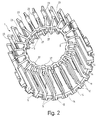
- Fig. 2
- xeine perspektivische Ansicht des Korbes von Fig. 1, gesehen mit Blickrichtung auf die hintere Bordseite des Kommutators;
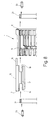
- Fig. 3
- einen Längsschnitt des Korbes, wobei in der oberen und der unteren Zeichnungshälfte der Schnitt in unterschiedlichen Schnittebenen geführt ist;
- Fig. 4 und 5
- Teilquerschnitte des Korbes entsprechend den Schnittlinien IV-IV bzw. V-V von Fig. 3;
- Fig. 6
- eine Seitenansicht eines im Korb aufnehmbaren Kupfersegmentes;
- Fig. 7
- eine Vorderansicht des Segmentes von Fig. 6;
- Fig. 8
- eine auseinander gezogen gezeichnete Teildarstellung des Korbes mit in diesen einsetzbarem Kupfersegment, zwei in den Korb einzusetzenden Armierungsringen sowie zwei zur Vervollständigung der Armierung einsetzbaren Keramikstiften und
- Fig. 9
- einen Teillängsschnitt des den Korb als eingeformtes Bauteil enthaltenden, fertiggestellten Kommutators.
Claims (12)
- Verfahren zum Herstellen von Kommutatoren, bei dem eine Mehrzahl von metallischen Segmenten (3) in voneinander isolierter und eine Kommutierungs-Schleifbahn bildender Lageanordnung angeordnet sind, um einen Segmentverband zu bilden, der zur Bildung eines Isolierkörpers mit darin eingebetteten Segmenten (3) mit einer preßformbaren, isolierenden Formmasse verpreßt wird, dadurch gekennzeichnet,
daß die Segmente (3) in einen Montagekorb (1) eingesetzt werden,
der zusammen mit dem Segmentverband mit der Formmasse so verpreßt wird, daß der Montagekorb (1) als bleibender, integraler Bestandteil in den Isolierkörper eingeformt wird, und daß für die Formmasse der für den Montagekorb (1) verwendete Werkstoff eingesetzt wird. - Verfahren nach Anspruch 1, bei dem zur Herstellung ringarmierter Kommutatoren vor dem Verpressen zumindest jeweils ein Armierungsring (21) in den Montagekorb (1) eingesetzt wird.
- Verfahren nach Anspruch 1 oder 2, dadurch gekennzeichnet, daß eine den Durchmesser einer axialen Bohrung des Kommutators definierende Metallbüchse (29) beim Verpressen mit der Formmasse in den Isolierkörper eingeformt wird.
- Verfahren nach einem der Ansprüche 1 bis 3, dadurch gekennzeichnet, daß der Montagekorb (1) aus einem Duroplast, Thermoplast oder keramischem Werkstoff hergestellt wird.
- Kommutator, hergestellt nach dem Verfahren nach einem der Ansprüche 1 bis 4, dadurch gekennzeichnet,
daß der Isolierkörper einen in die Formmasse eingeformten, als isolierender Tragkörper für den Segmentverband dienenden Montagekorb (1) enthält, und daß der Montagekorb (1) aus dem auch als Formmasse verwendeten Werkstoff hergestellt ist. - Kommutator nach Anspruch 5, dadurch gekennzeichnet, daß der Montagekorb (1) eine Mehrzahl von Stegen (5) besitzt, die sich in gleichen gegenseitigen Abständen voneinander von einem sie in ihrem Fußbereich verbindenden Innenring (9) des Korbes (1) radial zum Umfang des Korbes (1) erstrecken, wo sie an einer Stirnseite durch einen Außenring (11) verbunden sind, und daß die Stege (5) im Umfangsbereich des Korbes (1) Aufnahmen für die zwischen den Stegen sitzenden Segmente (3) bilden.
- Kommutator nach Anspruch 6, dadurch gekennzeichnet, daß der Außenring (11) eine in einer Radialebene liegende Anschlagfläche (12) für die ihren Anschlußhaken (15) zugeordneten Enden der Segmente (3) bildet und daß der Außenring (11) Durchbrüche (14) für den Durchtritt der Haken (15) der Segmente (3) aufweist.
- Kommutator nach Anspruch 6 oder 7, dadurch gekennzeichnet, daß die Stege (5) in zumindest einem ihrer axialen Endbereiche Sitzflächen (23, 25) für die Anlage der äußeren Umfangsfläche eines in den Korb (1) eingesetzten Armierungsringes (21) bilden.
- Kommutator nach einem der Ansprüche 6 bis 8, dadurch gekennzeichnet daß die Stege (5) zur Bildung von Absätzen abgestuft sind.
- Kommutator nach Anspruch 8 oder 9, dadurch gekennzeichnet, daß
die Segmente (3) in ihrem Fußteil (17) an zumindest einem ihrer Enden eine Ausnehmung (19) aufweisen, die sich vom betreffenden Ende des Segments (3) axial nach innen erstreckt, und daß die Sitzflächen (23, 25) für die Anlage des zumindest einen Armierungsringes (21) an den Stegen (5) innerhalb der Ausnehmungen (19) der im Korb (1) befindlichen Segmente (3) und in einem radialen und axialen Abstand zur Begrenzung der Ausnehmungen (19) gelegen sind. - Kommutator nach Anspruch 10, dadurch gekennzeichnet, daß
die Segmente (3) durch Profilkörper gebildet sind, deren Fußteil (17) seitliche Einkerbungen (31) aufweist, die Halteflächen für die Anlage von zwischen die Stege (5) des Korbes (1) einsetzbaren, sich axial erstreckenden Stiften (33) bilden, die sich an der Innenseite des zugeordneten Armierungsringes (21) abstützen. - Kommutator nach Anspruch 11, dadurch gekennzeichnet, daß die Stifte (33) aus einem keramischen Werkstoff bestehen.
Priority Applications (1)
| Application Number | Priority Date | Filing Date | Title |
|---|---|---|---|
| SI9730179T SI0931369T1 (en) | 1996-10-12 | 1997-09-11 | Method for manufacturing commutators and commutator made according to this method |
Applications Claiming Priority (3)
| Application Number | Priority Date | Filing Date | Title |
|---|---|---|---|
| DE19642138 | 1996-10-12 | ||
| DE19642138A DE19642138A1 (de) | 1996-10-12 | 1996-10-12 | Verfahren zum Herstellen von Kommutatoren und nach dem Verfahren hergestellter Kommutator |
| PCT/EP1997/004970 WO1998016979A1 (de) | 1996-10-12 | 1997-09-11 | Verfahren zum herstellen von kommutatoren und nach dem verfahren hergestellter kommutator |
Publications (2)
| Publication Number | Publication Date |
|---|---|
| EP0931369A1 EP0931369A1 (de) | 1999-07-28 |
| EP0931369B1 true EP0931369B1 (de) | 2001-05-23 |
Family
ID=7808576
Family Applications (1)
| Application Number | Title | Priority Date | Filing Date |
|---|---|---|---|
| EP97909250A Expired - Lifetime EP0931369B1 (de) | 1996-10-12 | 1997-09-11 | Verfahren zum herstellen von kommutatoren und nach dem verfahren hergestellter kommutator |
Country Status (4)
| Country | Link |
|---|---|
| EP (1) | EP0931369B1 (de) |
| DE (2) | DE19642138A1 (de) |
| ES (1) | ES2158509T3 (de) |
| WO (1) | WO1998016979A1 (de) |
Families Citing this family (4)
| Publication number | Priority date | Publication date | Assignee | Title |
|---|---|---|---|---|
| DE19922235C2 (de) * | 1998-08-21 | 2002-05-23 | Kirkwood Ind Gmbh | Kommutator und Verfahren zur Herstellung eines Kommutators |
| DE19837961C2 (de) * | 1998-08-21 | 2001-08-16 | Kirkwood Ind Gmbh | Kommutator und Verfahren zur Herstellung eines Kommutators |
| DE10250261A1 (de) * | 2002-10-28 | 2004-06-09 | Kolektor D.O.O. | Kommutator für eine elektrische Maschine und Verfahren zu seiner Herstellung |
| CN101740985B (zh) * | 2008-11-18 | 2014-03-12 | 广东德昌电机有限公司 | 换向器及其制造方法 |
Family Cites Families (9)
| Publication number | Priority date | Publication date | Assignee | Title |
|---|---|---|---|---|
| GB1135654A (en) * | 1966-07-06 | 1968-12-04 | Lubomir Svatek | Improvements in or relating to electrical rotary machines |
| US3643314A (en) * | 1970-07-22 | 1972-02-22 | Kaut & Bux Ohg | Device for spacing the segments of a commutator |
| US4056882A (en) * | 1973-10-05 | 1977-11-08 | Airscrew Howden Limited | Method of making a dimensionally stable commutator |
| DE7634129U1 (de) * | 1976-10-29 | 1977-02-10 | Fa. Heinrich Menke Jun., 5750 Menden | Kunststoffleisten zur Herstellung von trommeiförmigen PreBstoffkommutatoren |
| DE3003825A1 (de) * | 1980-02-02 | 1981-08-13 | Friedrich Nettelhoff Beleuchtungskörper-und Metallwarenfabrik, 5750 Menden | Distanzierelement |
| DE3812585A1 (de) * | 1987-04-16 | 1988-11-03 | Nettelhoff Friedrich Fa | Kollektor fuer einen elektromotor sowie armierungsring zu diesem |
| GB2214723B (en) * | 1988-01-19 | 1992-01-29 | Johnson Electric Ind Mfg | A commutator |
| FR2670334A1 (fr) * | 1990-12-06 | 1992-06-12 | Cheveux Yves | Collecteur moule pour machine tournante electrique du type tambour. |
| DE4302853C1 (de) * | 1993-02-02 | 1994-02-03 | Bosch Gmbh Robert | Kommutator für elektrische Maschinen und Verfahren zur Herstellung eines Kommutators |
-
1996
- 1996-10-12 DE DE19642138A patent/DE19642138A1/de not_active Withdrawn
-
1997
- 1997-09-11 EP EP97909250A patent/EP0931369B1/de not_active Expired - Lifetime
- 1997-09-11 DE DE59703617T patent/DE59703617D1/de not_active Expired - Lifetime
- 1997-09-11 WO PCT/EP1997/004970 patent/WO1998016979A1/de not_active Ceased
- 1997-09-11 ES ES97909250T patent/ES2158509T3/es not_active Expired - Lifetime
Also Published As
| Publication number | Publication date |
|---|---|
| DE19642138A1 (de) | 1998-04-23 |
| DE59703617D1 (de) | 2001-06-28 |
| ES2158509T3 (es) | 2001-09-01 |
| WO1998016979A1 (de) | 1998-04-23 |
| EP0931369A1 (de) | 1999-07-28 |
Similar Documents
| Publication | Publication Date | Title |
|---|---|---|
| DE69502638T2 (de) | Herstellungsverfahren eines ebenen Kohlesegmentkommutators. | |
| DE3702012C2 (de) | ||
| DE69409317T2 (de) | Kollektor für Wechselstromgenerator hauptsächlich für Kraftfahrzeuge | |
| DE69327466T2 (de) | Schlauchkupplung und klemmhülse dafür sowie herstellungsverfahren | |
| DE2124078A1 (de) | Schleifringe-Satz für elektrische Maschinen und Verfahren zu seiner Herstellung | |
| DE69410200T2 (de) | Kollektor für einen Wechselstromgenerator, insbesondere für ein Kraftfahrzeug | |
| EP1232543B1 (de) | Plankommutator, verfahren zu seiner herstellung sowie leiterrohling zur verwendung bei seiner herstellung | |
| DE4117803C2 (de) | ||
| DE1525039A1 (de) | Federgelenk und Verfahren zur Herstellung desselben | |
| DE19525584A1 (de) | Verfahren zur Herstellung eines Plankommutators | |
| EP0931369B1 (de) | Verfahren zum herstellen von kommutatoren und nach dem verfahren hergestellter kommutator | |
| DE69931620T2 (de) | Verfahren und werkzeug zur herstellung einer antenneneinheit sowie antenneneinheit | |
| DE10250261A1 (de) | Kommutator für eine elektrische Maschine und Verfahren zu seiner Herstellung | |
| DE10359473A1 (de) | Plankommutator | |
| EP0350855B1 (de) | Kommutator und Verfahren zu seiner Herstellung | |
| DE836969C (de) | Kommutator | |
| DE19912614A1 (de) | Spalttopf für Kreiselpumpe | |
| DE2511302C3 (de) | Verfahren zur Herstellung eines Wellendichtringes | |
| DE102004008958A1 (de) | Verfahren zur Herstellung einer Bremsscheibe, Bremsscheibe und Verbindungselement | |
| EP4283838B1 (de) | Rotoraufnahme zur herstellung einer verbindung einer welle mit einem rotorblechpaket für einen rotor eines innenläufermotors | |
| DE102023134102B4 (de) | Stromableitelement | |
| DE102023100765B4 (de) | Rad aus Kunststoff, Herstellungsverfahren und Kunststoffspritzgussform | |
| EP0573439B1 (de) | Rollkommutator für elektrische maschine. | |
| EP0524393B1 (de) | Verfahren zur Herstellung eines Kommutators und Vorrichtung zur Durchführung des Verfahrens | |
| DE102023132749A1 (de) | Verfahren zum Herstellen eines Bauteils, das eine Funktionseinrichtung und einen stabförmigen metallischen Körper umfasst |
Legal Events
| Date | Code | Title | Description |
|---|---|---|---|
| PUAI | Public reference made under article 153(3) epc to a published international application that has entered the european phase |
Free format text: ORIGINAL CODE: 0009012 |
|
| 17P | Request for examination filed |
Effective date: 19990211 |
|
| AK | Designated contracting states |
Kind code of ref document: A1 Designated state(s): DE ES FR IT SE |
|
| AX | Request for extension of the european patent |
Free format text: SI PAYMENT 19990211 |
|
| RTI1 | Title (correction) |
Free format text: METHOD FOR MANUFACTURING COMMUTATORS AND COMMUTATOR MADE ACCORDING TO THIS METHOD |
|
| GRAG | Despatch of communication of intention to grant |
Free format text: ORIGINAL CODE: EPIDOS AGRA |
|
| GRAG | Despatch of communication of intention to grant |
Free format text: ORIGINAL CODE: EPIDOS AGRA |
|
| GRAH | Despatch of communication of intention to grant a patent |
Free format text: ORIGINAL CODE: EPIDOS IGRA |
|
| 17Q | First examination report despatched |
Effective date: 20000926 |
|
| GRAH | Despatch of communication of intention to grant a patent |
Free format text: ORIGINAL CODE: EPIDOS IGRA |
|
| GRAA | (expected) grant |
Free format text: ORIGINAL CODE: 0009210 |
|
| AK | Designated contracting states |
Kind code of ref document: B1 Designated state(s): DE ES FR IT SE |
|
| AX | Request for extension of the european patent |
Free format text: SI PAYMENT 19990211 |
|
| ITF | It: translation for a ep patent filed | ||
| REF | Corresponds to: |
Ref document number: 59703617 Country of ref document: DE Date of ref document: 20010628 |
|
| ET | Fr: translation filed | ||
| REG | Reference to a national code |
Ref country code: ES Ref legal event code: FG2A Ref document number: 2158509 Country of ref document: ES Kind code of ref document: T3 |
|
| PLBE | No opposition filed within time limit |
Free format text: ORIGINAL CODE: 0009261 |
|
| STAA | Information on the status of an ep patent application or granted ep patent |
Free format text: STATUS: NO OPPOSITION FILED WITHIN TIME LIMIT |
|
| 26N | No opposition filed | ||
| REG | Reference to a national code |
Ref country code: SI Ref legal event code: IF |
|
| REG | Reference to a national code |
Ref country code: ES Ref legal event code: PC2A |
|
| REG | Reference to a national code |
Ref country code: FR Ref legal event code: CD |
|
| REG | Reference to a national code |
Ref country code: SI Ref legal event code: SP73 Owner name: KAUTT & BUX GMBH; DE Effective date: 20050823 |
|
| PGFP | Annual fee paid to national office [announced via postgrant information from national office to epo] |
Ref country code: ES Payment date: 20070903 Year of fee payment: 11 |
|
| PGFP | Annual fee paid to national office [announced via postgrant information from national office to epo] |
Ref country code: IT Payment date: 20070919 Year of fee payment: 11 |
|
| REG | Reference to a national code |
Ref country code: ES Ref legal event code: PC2A |
|
| PGFP | Annual fee paid to national office [announced via postgrant information from national office to epo] |
Ref country code: SE Payment date: 20070926 Year of fee payment: 11 |
|
| PGFP | Annual fee paid to national office [announced via postgrant information from national office to epo] |
Ref country code: FR Payment date: 20070925 Year of fee payment: 11 |
|
| REG | Reference to a national code |
Ref country code: SI Ref legal event code: SP73 Owner name: KOLEKTOR KAUTT & BUX GMBH; DE Effective date: 20080222 |
|
| REG | Reference to a national code |
Ref country code: FR Ref legal event code: CD |
|
| REG | Reference to a national code |
Ref country code: SI Ref legal event code: KO00 Effective date: 20090508 |
|
| REG | Reference to a national code |
Ref country code: FR Ref legal event code: ST Effective date: 20090529 |
|
| PG25 | Lapsed in a contracting state [announced via postgrant information from national office to epo] |
Ref country code: IT Free format text: LAPSE BECAUSE OF NON-PAYMENT OF DUE FEES Effective date: 20080911 |
|
| PG25 | Lapsed in a contracting state [announced via postgrant information from national office to epo] |
Ref country code: FR Free format text: LAPSE BECAUSE OF NON-PAYMENT OF DUE FEES Effective date: 20080930 |
|
| REG | Reference to a national code |
Ref country code: ES Ref legal event code: FD2A Effective date: 20080912 |
|
| PG25 | Lapsed in a contracting state [announced via postgrant information from national office to epo] |
Ref country code: ES Free format text: LAPSE BECAUSE OF NON-PAYMENT OF DUE FEES Effective date: 20080912 |
|
| PG25 | Lapsed in a contracting state [announced via postgrant information from national office to epo] |
Ref country code: SE Free format text: LAPSE BECAUSE OF NON-PAYMENT OF DUE FEES Effective date: 20080912 |
|
| PGFP | Annual fee paid to national office [announced via postgrant information from national office to epo] |
Ref country code: DE Payment date: 20100924 Year of fee payment: 14 |
|
| REG | Reference to a national code |
Ref country code: DE Ref legal event code: R119 Ref document number: 59703617 Country of ref document: DE Effective date: 20120403 |
|
| PG25 | Lapsed in a contracting state [announced via postgrant information from national office to epo] |
Ref country code: DE Free format text: LAPSE BECAUSE OF NON-PAYMENT OF DUE FEES Effective date: 20120403 |